

latigid on
-
Posts
2,516 -
Joined
-
Last visited
-
Days Won
147
Content Type
Profiles
Forums
Blogs
Gallery
Posts posted by latigid on
-
-
Just now, Psykhaze said:
Ok great thanks =)
I'll import my photoshop layout in illustrator in order to make a good sized DWG/DXF : this will be my base for components placements in Eagle for CS PCB and source for HPGL engraving in FrontPanel Designer.
While in illustrator , I'll import waveforms / routing algos and will shape the paths , this way it could be exported in DWG/DXF or in any graphical form.
I have a doubt regarding engraving "place" for routing algos (quite "big" graphics) , maybe some display could be done on the 4x20 LCD? I think the waveforms should be engraved on the frontpanel.The waveforms are already depicted on the CLCD, it's just a bit ugly. :)
Just now, Psykhaze said:I've downloaded the 1.9h MIOS8 and MBFM 1.4 "bios" . Checked the source. Sounds not too hard, even i am still new to this Assembly. Few questions are lasting , want to be sure:
- MBFM MIOS 1.4 is intended to run on a PIC18F4685 . So the source has much things already done in it with this PIC. And Wilba used these ones on MB-6582.
Is this still the right PIC for this project? (I do not intend to whole re-think everything)TK. would be the one to ask, but I think the PICs are interchangeable in the Core, so just use the recommended one.
Just now, Psykhaze said:- I found a PIC18FXX2 programming ref manual at http://ww1.microchip.com/downloads/en/DeviceDoc/39564c.pdf .
Is the instruction set detailed ok for this PIC ?How deep are you going? I think all of the routines are available in MIOS and could be reused (up to you however).
Just now, Psykhaze said:- Not related to MIOS, Is there any way i can access MB-6582 Eagle Files to take it as a start for my PCB design ?
I think the PCBs were designed in KiCAD, and the layouts aren't publicly available. Did you decide to follow the MB-6582 form exactly? Are you using a PacTec case?
Just now, Psykhaze said:
- Can I open a wiki page for this project?
Thanks in advance for your answers,
Best regards,
JKI think you need an admin to create a wiki account for you.
-
-
It's a commendable idea and I wish you the best of luck!
There are a few points to consider though. When Wilba first designed the MB-6582 (as far as I know) companies such as Ponoko/Formulor didn't exist or weren't well established. Your options for cases were limited to alu front panels from Schaeffer/FPE and a 40cm deep rack case -- quite impractical. Now there are good alternatives to make plastic cases, see for example the Mutable Instruments DIY stuff, sammichSID/FM, Sonic Potions LXR, Yocto etc. etc. Even complete folded metal cases (BLM, TubeOhm Ambika) are possible with minimal cost and effort. For me, it's important to design to maximise playability and longevity, which might otherwise be wasted on a device which sits half-finished, broken or unwanted in the corner.
The best way forward is (I think) to design all of the parts from the beginning, so how the front panel works with the case, the connectors, heat management etc. I would propose sandwich-type connectors over the SIL ribbons used in the MB-6582. Much more durable and you can take the thing apart if needed. You can still use an angled case, just the IO will need panel mount or another PCB. Think about modular blocks, like OPL3 and Core8 sub-boards that plug into a CS. It's cheaper to buy multiple copies of PCBs rather than large ones and can make troubleshooting easier. Shift registers could be placed on the CS PCB (e.g. SEQ) or like a backpack as I did for my MBCV concept.
Something that a 32-bit Core might be useful for is display options. Part of the mystery of FM synthesis is how all of the operators/modulators interact to create your sound. If there were graphical representations of waveforms/levels/routing I think that would be a great contribution. E.g. look at the SSD1306 0.96" OLEDs in use in MBCV/Programma with SPI drivers already well integrated into MIOS32.
-
1 hour ago, novski said:
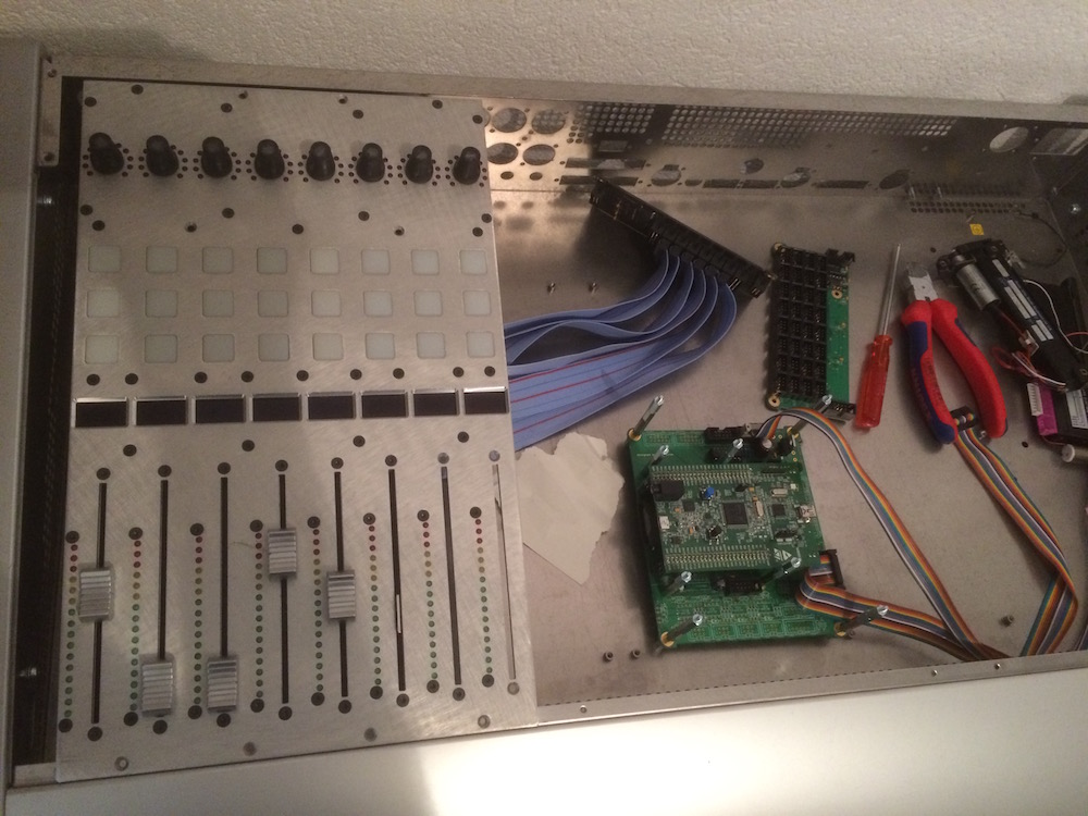
Well the Faders are made with the MF_NG 8bit uC in old fashion. Its a bit tricky to geth them to talk in a chain but Touch works with the crome knobs...
Ah, I see the MF_NG module now, with the strobe line pulsing from RD4/pin 27. This makes perfect sense.
-
First off, did you upload the correct firmware using the Wilba variant?
-
1 hour ago, novski said:
Thats the momentary situation

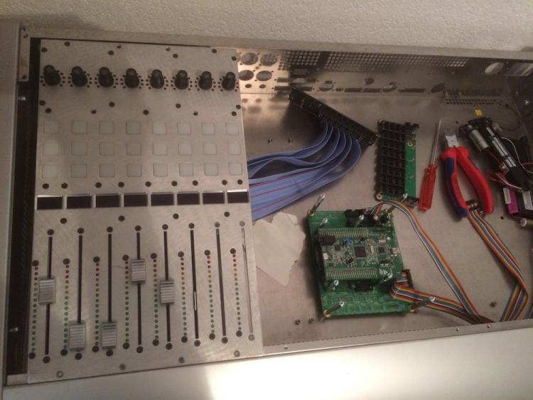
Regards, Novski
Looks nice! Is there a current method of using touch sensors for the faders on a 32-bit Core? We're missing the J14 strobe line present on the old PIC Core. Seems to have been ported in software at least.
-
They're very useful and cost 1 cent for 1000 :). If you ever go for the full SEQ BLM that's 1/3rd gone!
-
Hello again :)
No problem to use the switch as an input for a DIN. Just connect one side to ground and the other to the appropriate pin on the module. There's no need for diodes unless you're configuring a switch matrix.
-
According to adafruit, there are at least two LEDs with different names that use the same controller (or an equivalent). I think they should work; you should choose the 5mm LED as 8mm is too large.
At some point I will sell the PCBs to suit (don't buy Sparkfun PCBs unless you want to use common RGB LEDs), price should be about 8 EUR.
If you read through TK.'s code example on svnmios32, he states that driving the LEDs takes up quite a bit of memory but not too much CPU overhead. There is a limit in the chain length in order to guarantee data transmission. I'm pretty sure that the controllers hold the colour value and new data is only required for updates. The advantage of shift registers is the parallel data transmission which allows for a simple serial stream to rapidly clock multiple lines. Disadvantages are the complicated PCB and software matrices, but it does work (BLM 16*16+X).
Bon weekend,
-
 1
1
-
-
If you can verify that the hex is written, it should be okay. I think the point of selecting the device (manually) is that the burner knows what programming voltage to use.
-
1
-
-
Did you find the build guide page?
http://www.midibox.org/dokuwiki/doku.php?id=wilba_mb_6582_base_pcb_construction_guide
You want to follow "Power Option D"http://www.midibox.org/dokuwiki/lib/exe/fetch.php?media=mb-6582:mb-6582_base_pcb.pdf
This is the PCB layout, so you should either jumper pins on the power switch directly to J4 or add bridges e.g. to bypass the 9V regulator.Hope that helps,
-
DOUT can also provide a type of PWM, but it only works well when the LEDs are addressed individually (i.e. not in a matrix). Which means quite a lot of DOUT pins. A better method is to use WS2812 LEDs which respond to a serial data chain. See the end of that thread for working layouts with 4*4 Sparkfun button pads and illuminated encoders.
-
Apparently you have to set the LXR BPM to 0 to slave to an external clock, it sounds like the LXR is getting confused with two clock sources.
http://wiki.sonic-potions.com/index.php/LXR_Owners_Manual#MIDI_clock_sync
-
Just to clarify; do you think the three rectangular boards (4*OLED; 2*OLED, 1 enc; 6*buttons 2*OLED) are too far away from the encoders? I have the 4*4 illuminated encoder boards already, but my idea was to create another PCB which holds 4*OLEDs mounted at 45 degrees as per the Programma design, which is stacked over the encoder board. So I think that's what you suggest: displays mounted as close as possible to encoders? Sorry if that's confusing, the rectangular boards are useful for different kinds of NG builds or as the menu interface for Programma.
I completely agree about the modularity though. You should be able to start with as many (up to 4) or few encoder boards and displays as you need and scale from there. If the arrangement doesn't suit you could also add distance between them or lay them out e.g in a straight line.
-
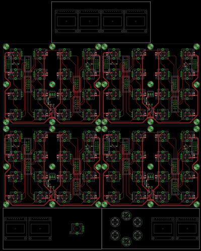
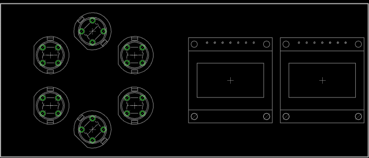
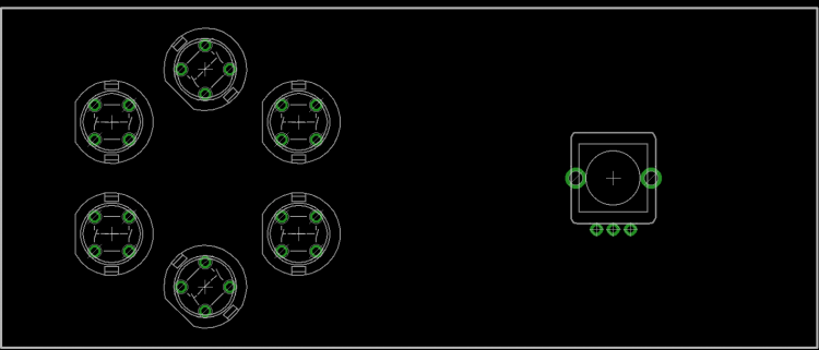
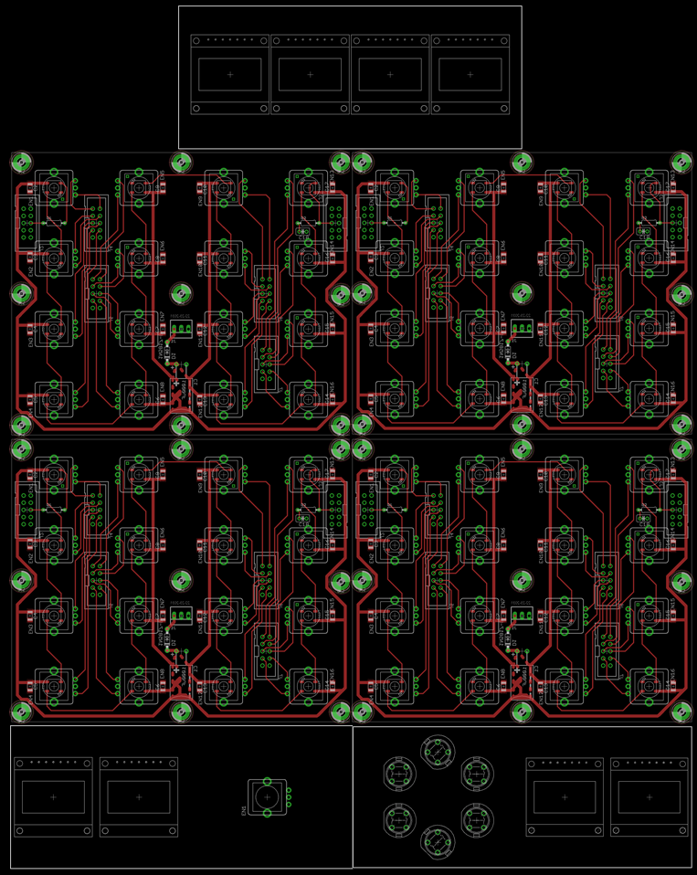
You mean for the Programma? That's better explained in their thread but for my variation it's something like this:
Potential layout of 8*8 grid with extra displays, top is for displaying 1 or more custom envelope curves, bottom has an "SCS" built with 4*OLED and, 6 buttons, 1 encoder:
-
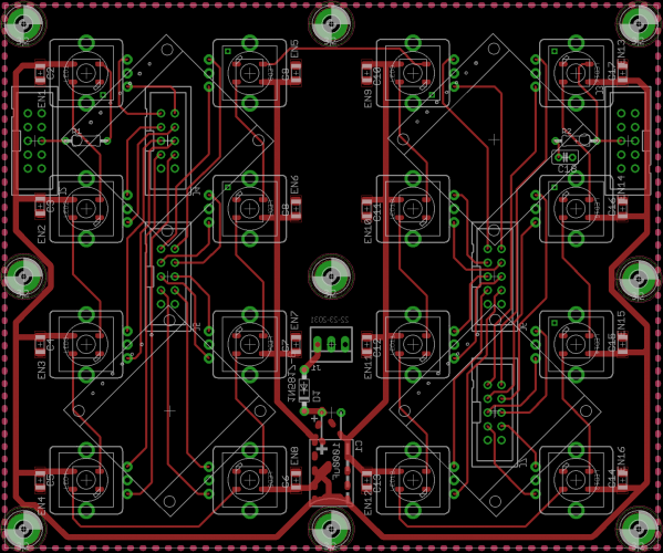
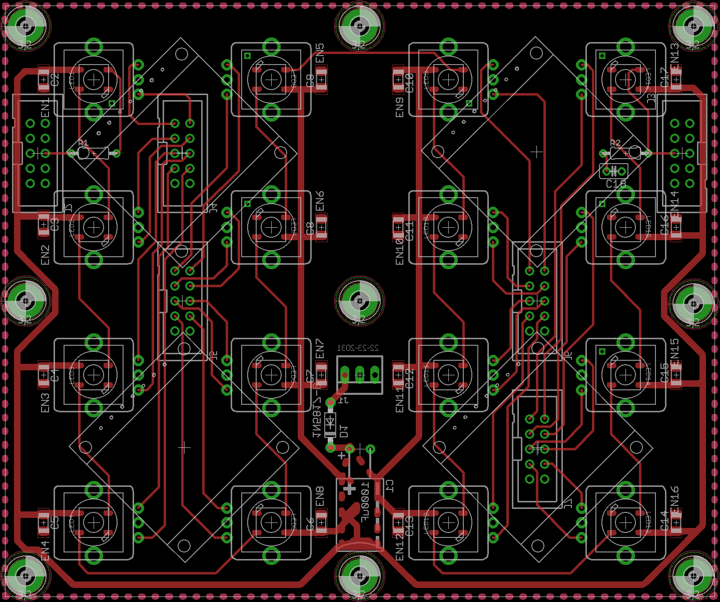
I'm working a bit with @Hawkeye and @jojjelito on their awesome MB-Programma project, only we'll try to use my illuminated encoders in place of the sadly obsolete LRE boards.
The Programma makes good use of displays mounted at 45 degrees to label each encoder. But to do this it requires quite a mishmash of wiring. I propose a new PCB set to make things easier, not just for Programma but a range of NG builds. I'm still working on the 45 degree board, but I have a fair idea of the others should work.
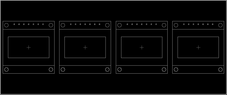
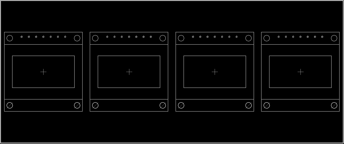
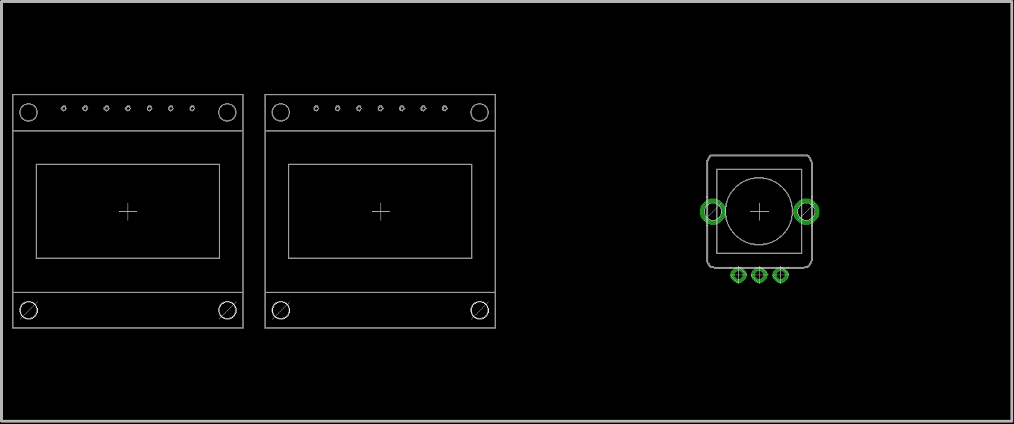
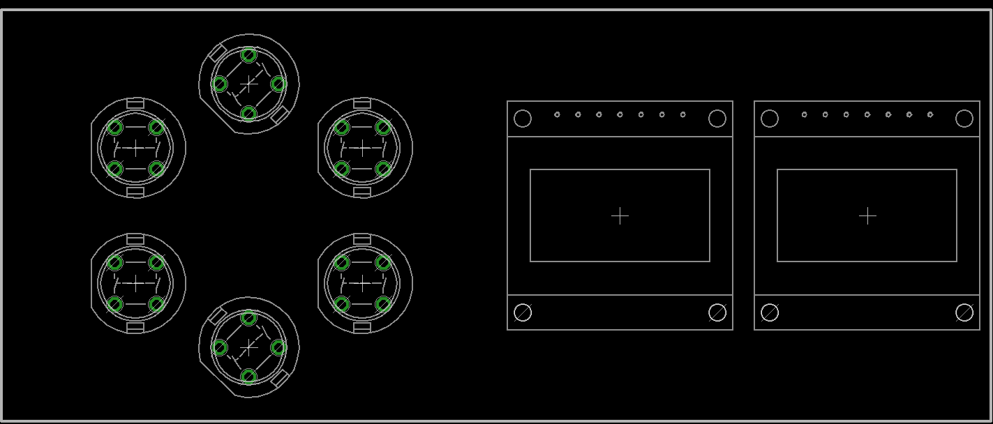
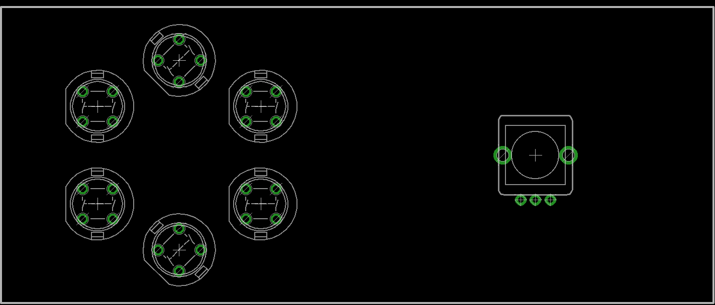
Here's how 4 OLEDDs look. This 7-pin type is very common and quite cheap. Spacing is at 30mm on a 120mm PCB.
I thought it would be interesting to combine a sort of SCS, a bit different in layout to @ilmenator's. 10mm switch footprints will also be added.
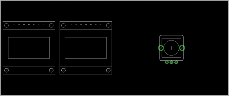
You could split the SCS over two PCBs (using a single ribbon with two connectors on it) or a single PCB if you liked.
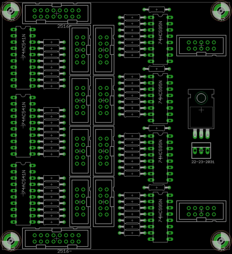
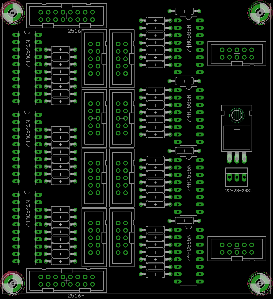
Once you go over 8 OLEDs, you need to start using DOUTs to generate the #CS (chip select/slave select) lines. It was mentioned that the Programma had a few issues with signal integrity, so I thought it might be an idea to combine a line driver with a shift register chain, and also an optional power regulator circuit. Adding to this, the new F4 Core J10B doesn't use 1:1 pinning with J1 on a DOUT board, so would need a special cable. I found some discussion that a similar circuit using 541 drivers and 1k output resistors could happily drive an array of displays spaced 10 metres in each direction. The resistor also acts as "termination" which attenuates reflections in the data lines. I will also add RC termination on the carrier boards. I didn't buffer the 595 outputs as they have reasonable source current already and #CS is less critical for timing. Apparently the displays run at 22mA each, so a linear Vreg should be okay to drive 32. Standard ribbon wire can take 500mA per per strand, again we should be okay, but I'll put an alternative power option on the carrier board.
Two driver boards could be chained for a possible 64 OLEDs (!). If possible I will try to connect the remaining #CS lines so one could drive 8 additional displays, though I think 64 is the limit. @Hawkeye suggests that it's better to use #CS from one source only to avoid problems i.e. directly from J15A or DOUTs.
Any questions or comments, please share!
-
1
-
-
Ah sorry, the text is quite small!
-
I think for this circuit you'd get quite low range, LM324 is not rail to rail and the maximum output at 5V supply is 3.5V. So less for 3v3 -- 1.8V? MCP600x is more suitable and very cheap.
Sorry, I don't have real experience in trigger circuits, but these look quite simple to try out.
-
Good luck! I know a lot of professional drum triggers use this scheme. E.g. ddrum; they also have a "brain" which must be a simple ADC to MIDI. Bare piezo elements cost almost nothing, although you may need to experiment with the damping material e.g. a piece of foam.
Zeners have a fixed breakdown voltage (wide range available), whereas Schottkys have a lower forward voltage than a standard PN junction (4148). The normal idea with MCU pin protection is to use Schottkys as a shunt. The lower Vf is, the more range you have, as the clipping point is the reference voltage (upper limit) - Vf. To protect from overvoltage you connect the anode to the pin and the cathode to 3v3. This ensures nothing greater that 3v3 can pass, it's also normal to include one or two current limiting resistors. To protect from undervoltage you connect the anode to ground and the cathode to the pin.
I would suggest using the op amp itself as a limiter, because it's impossible for the output to swing past the power rails. There are protection diodes at work here too, so you need a rail to rail op amp in order to maximise the signal transmission.
-
Like it! Nice job!
-
1
-
-
Have you though about a piezo trigger? You may get a lot of feedback with a microphone. For this too you'd need a processing circuit as I think piezo elements can generate a high voltage (low current).
This one is very simple (open source):
http://musicthing.co.uk/modular/?p=933It might be quite difficult to separate the rim and body sounds.
The Zener (better Schottky) diode would be unnecessary if you used a rail-to-rail op amp powered at 3v3 and your scaling circuit was tailored to give a correct signal voltage.
-
Do you mean you want to assign a track to an AOUT port? This would be done by setting up the track on the AOUT channel of your choice.
You can also route a MIDI input to an AOUT port just like a MIDI-CV converter.
Or do you mean something else? It's not so clear from your question.
-
DIAMEX PIC PROG works fine and is the recommendation of TK. Or, send the PICs to one of many on the forum and we can program them for you :).
I had two PICs from SmashTV (since several years) two from Mike (since a few years) and two virgin ones from Mouser. Of the pre-burned ones, one was faulty, even after erasing and re-flashing. So I'm sure the PICs from Mike had the bootloader burned in, but maybe a handling error on my side caused an issue. In any case, I have the Quad IIC working well now!
-
Okay, I understand what you mean. LED brightness does depend on the current limiting resistor, but it's a non-linear relationship. Brightness is much more dependent on the pulse width (or pulse density). I think the duty cycle in the BLM is 10%, not so easy to calculate brightness.
The red LED does have a lower Vf, but also a lower mcd rating than green. In my experience, 220R was a good balance for both red and green LEDs. You might also get some feedback from others here who have mixed red and green LEDs in their builds.
If you want, here is a shared OSHpark project for very cheap test boards, you could also check the fitting of your new LEDs.
https://www.oshpark.com/shared_projects/I9xfP7XE
"Step C" CS Design for MBFM with Base PCB
in MIDIbox FM
Posted
My MBFM knowledge is limited to a sammichFM, but I'm sure the routing is also depicted graphically on the CLCD.* As I said already, this is not very intuitive and would be great if there was a more graphical depiction on OLEDs of all waves/routing/levels etc. This is more a limitation of having one encoder and 4 buttons as a control surface, but I think even with the full v1 FM CS that TK. designed it's still tricky.
*It might be a good idea to first build basic Core/FM modules and see how the MIOS8 software works.
It's great that you're very motivated, and you will need that for a project like this. Expect many hours/months spent and probably one or more buggy PCBs the first time that you order. If you haven't done PCB design before it's a steep learning curve. If you don't have a professional version of EAGLE you'll have a lot of trouble designing a PCB this size. I'm not sure of a PCB design package that is free and allows for large boards.
You see straight away the benefit of 32-bit: only one Core. With two you need to work in CAN bus, MIDI implementation etc. In my opinion, it only makes sense to use the 8-bit Core for existing applications, or maybe when you need a good ADC. No one is going to stop you, and of course any new work is definitely encouraged, but from the start the technology is on the verge of obsolescence.
We have to look at history here: there are a lot of people who dream very big, only to run out of time, patience or money along the way. It's not to say that you'll be the same, only that if you make things easier for yourself they will have a much greater chance of success.
There's no problem (in my view) in keeping the discussion running, it's really a good thing to see projects and ideas flying about.