

latigid on
-
Posts
2,516 -
Joined
-
Last visited
-
Days Won
147
Content Type
Profiles
Forums
Blogs
Gallery
Posts posted by latigid on
-
-
Try also adjusting the contrast/brightness pots.
-
Could work, but you'd need a custom firmware and separate select lines for each LCD.
http://www.ucapps.de/mbhp/mbhp_nxclcd_mios32.pdf
http://www.ucapps.de/mbhp_lcd.html
MIOS8: A special driver module is available which allows to connect up to 8 CLCDs to a single core (clcd_multi). Displays have to be selected with the USER_LCD_Select function by the application. Connectivity: any free pin of the PIC can be used for the enable line. For instance, if your application doesn't use the analog pins at J5 of the core module, you are able to connect 8 additional LCDs. You could also program a multiplexer interface in order to address even more LCDs by routing the enable line to one PIC pin. Wiring Diagram: mbhp_nxclcd_mios8.pdf MIOS32: the standard CLCD driver is prepared for controlling up to 256 devices selected via MIOS32_LCD_DeviceSet(). Please understand this value as a theoretical possibility, physical parameters (like cable capacities) have to be considered as well. ;-) Connectivity: see this MIDIbox NG Manual Chapter. Wiring Diagram: mbhp_nxclcd_mios32.pdf -
Something to add (not sure if it's covered by Hawkeye) is that you should mount longish spacers/standoffs to the PCB to allow the diode legs etc. to protrude through. Just take care of any plastic parts if they're in the vicinity, but going from low to high it shouldn't be a problem.
Have fun! It's generally a great and satisfying build.
-
Top work, and great realisation of your concept! Best of luck for the remaining HW integration.
-
I would recommend single "modules" as it's easier to get the needed material strength and increases the probability of the project actually being finished.
With the isomorphic keyboard, it seems quite similar to the Linnstrument?
-
Soldering though hole from the top is a great idea because it avoids you flipping the board and bending component leads/having them fall out. As long as the hole plating is good it's no problem. And it's likely that PCB traces will run on both sides anyway.
-
Maybe something to consider: with the sink driver transistors the "off" voltage will be raised approximately 1 PN (diode) junction above 0V/ground. Perhaps then if the supply is noisy (?) the TTL low threshold is crossed unintentionally. So I'd expect better results with HC parts.
-
No, but they are useful for "fast" functions.
-
 1
1
-
-
28 minutes ago, enron_hubbard said:
Looks pretty excellent - if I'm seeing this right, this is designed for through-hole RGBLEDs, yes? With 3x headers to for a DOUT module and a single one for the buttons to DIN? So if I'm understanding correctly, you'd need a total of 3 DOUT headers for each 4x4 matrix, making a total of 12 DOUT modules to drive the LEDs alone (16*3 = 48 headers, 4 headers per DOUT). Part of why I was interested in the Livid boards is because, according to its documentation, you only need to connect 2x of the headers to their Brain module. No idea what the differences are in how CORE and Livid Brain address LEDs.
I'm planning on ordering the boards and parts for one of the Livid Omni RGB boards, as well as everything for a CORE and DIN/DOUT modules, mid next week to get ready to test. Excited to learn this platform!
Not quite, it uses 2812 programmable LEDs (5mm through hole) which are wired in a serial chain. This way you can cascade many button modules together and only one wire is used for the colour data. So you have data in and out, plus a 4*4 matrix (0.5*DINX1 + 0.5*DOUTX1) to scan the button presses. TK. has already demonstrated an animated rainbow of 64 LEDs this way.
With your omni board it will be possible to address each colour, you just need 48 DOUT pins per 4*4 array. So this is 1.5 DOUTX4 modules, plus 4 pins to scan the matrix, plus 4 pins on a DINX4 module to scan the other axis.
EDIT: okay, it looks like the Omni board has the LEDs connected in a matrix. So while you can address each one, I don't think it will work with PWM, for the same reason as TK. found before. If the LEDs are already time multiplexed then PWM becomes much less effective. The plating also appears to be HASL rather than ENIG. I would take ENIG every time because the surface is much more even and is less prone to surface oxidation. One other thing is that the buttons look to be singular and without guide nubs. In this respect, sheets of Sparkfun or adafruit are better to stay even.
I don't mean to bring anything down, I've just spent a lot of time assessing everything out there.
-
33 minutes ago, mongrol said:
On a side note I'm making a synth from an Axoloti, a Teensy and it includes a Trellis button pad. The Axo is completely controlled over Midi. This makes me think that a BLM could be made using a Teensy that talks to the SEQ over Midi using the BLM protocol. Teensy + Sparkfun pads + RGB leds could effectively be an easier build for a most people (no smd) Would this be possible?
There's a couple of problems with the Sparkfun pads, which is why (IMO) it took so long for a BLM solution to materialise. First, the size and cost of the components are quite large/high. This means that a whole lot of them will be very expensive, and the case will be larger, close to half a metre. The adafruit buttons are not only half the price but 3/4 the size, which makes a more affordable and playable instrument when a lot of them are stacked together. The downside is that the latter only fit 3mm single LEDs, meaning another solution had to be found. Hence the BLM PCB with reverse-mount SMD.
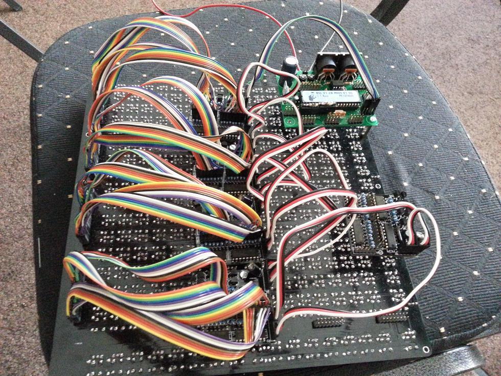
Second, the matrix is not well set up/optimised for BLM. With some clever cabling you might manage to emulate the complex matrix and scan the buttons/LEDs with SCALAR boards, but this adds to the cost and turns it into wire spaghetti! This is a picture of a previous BLM attempt by @diwib, unfortunately I don't think it made it as we never heard from him after September 2013.
Thus it's much simpler if all wiring and shift registers are on-board. A downside is that troubleshooting is much more difficult as there are many solder points to inspect.
Thirdly, a crucial element to the BLM is the extra row and column + shift button. Without custom PCBs it is very difficult to realise this both in terms of the matrix routing and finding a mounting solution.
In terms of SMD soldering, it is a bit of a learning curve, but almost all soldering is 1206/SOIC with a few SOT-23(-5). You remarked on Muff Wiggler that the ~300 diodes put you off, and you're correct that this is the most taxing part. There might be a more creative way to solder them in to make things easier, but for now it's an exercise in Zen Buddhism :)
33 minutes ago, mongrol said:I see the BLM uses more pins than the usual 2 pins for Midi and I can't find much about how the BLM is actually implemented in MIOS.
This is just MIDI in, MIDI out and power combined into one connector. The PSU is pushing the limits for effective line transmission (some people have extra holes in their cases for external power) but it seems to work as is. I have an extra buck/boost regulator installed which improves the power rail stability. The BLM is just a "dumb" display as far as programming is concerned. It simply reacts to MIDI sent by a 32-bit Core and generates MIDI upon button presses. The ADCs are also working to transmit slider values and/or external CV into the SEQ.
33 minutes ago, mongrol said:Another question. Is a BLM with single LED's not possible or usable? Trellis's are very simple to build with and connect a 16x8 matrix easily over i2c.
It's not really a BLM without duo-LEDs :). It could work but I would recommend a monome in this case. Also I2C is much slower than the matrix protocol used in the BLM.
-
Great, we're nearly at the point where I can think about the order.
For the multiple edits, definitely you can select more than one track at a time by holding down track buttons. The display will change from GxTy to GxTM for two or three, or GxTA for all tracks of a group selected. I didn't realise this before -- that's why we need jjonas' user manuals! It's amazing how deep the SEQ goes. It's helpful to have the BLM (or TPD) to keep "track" of where everything is.
-
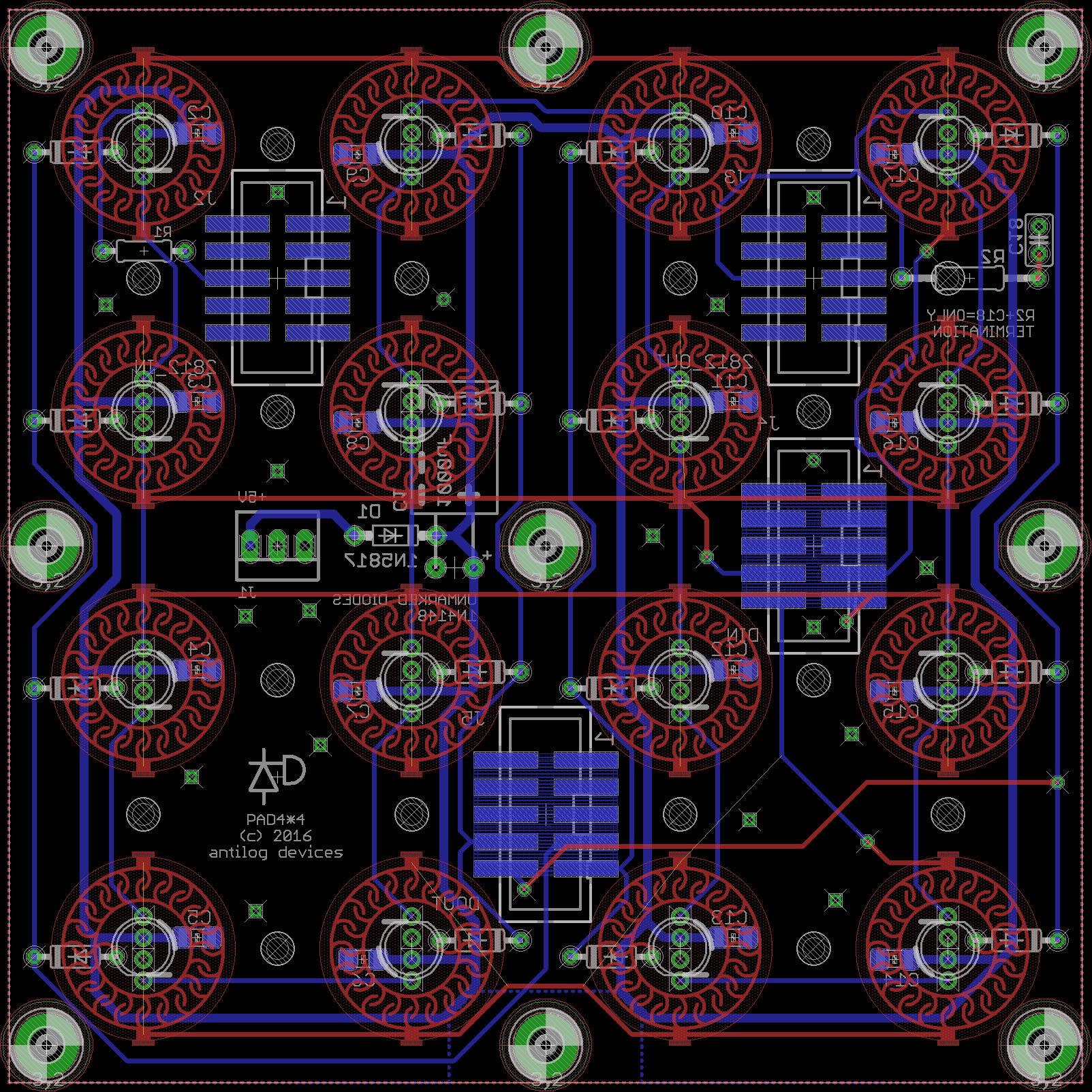
This is my take on the 4*4 matrix, prototypes ordered yesterday.

It's designed for 2812 LEDs and Sparkfun button pads. In this way the matrix wiring is easier, and should be more programmable. TK. tried to PWM RGB LEDs with DOUT/DIN boards but the control was poor. It did work with individual DOUT pins, but then you have to dedicate a lot of modules to a single board.
If the concept works I will offer PCBs in the future.
-
1
-
-
It's possible to export the part list like so:
Partlist Exported from noisegate_tonepad_4_stereo.brd at 18/02/2016 21:53 EAGLE Version 7.5.0 Copyright (c) 1988-2015 CadSoft Assembly variant: Part Value Package Library Position (mm) Orientation 1 78XXS v-reg (13.97 50.165) R0 9VDC 1X02 pinhead (46.355 11.1125) R90 ATTACK1 PT-10S pot (6.35 2.54) R0 ATTACK2 PT-10S pot (42.2275 47.3075) R180 C1 47nF C025-024X044 ref-packages (38.735 18.0975) R0 C2 10nF C025-024X044 ref-packages (33.02 13.6525) R270 C3 100nF C025-024X044 ref-packages (28.8925 8.5725) R270 C4 47nF C025-024X044 ref-packages (18.415 14.9225) R180 C5 47nF C025-024X044 ref-packages (13.0175 14.9225) R180 C6 10uF E2,5-5 rcl (41.91 11.43) R90 C7 10uF E2,5-5 rcl (37.7825 7.62) R90 C8 10uF E2,5-5 rcl (25.0825 6.0325) R180 C9 1uF E2,5-5 rcl (20.32 2.8575) R180 C10 1uF E2,5-5 rcl (17.78 19.685) R270 C11 1uF E2,5-5 rcl (11.1125 10.16) R180 C12 1uF/NP C025_050-035X075 rcl (13.0175 22.5425) R180 C13 47nF C025-024X044 ref-packages (9.8425 31.75) R180 C14 10nF C025-024X044 ref-packages (15.5575 36.195) R90 C15 100nF C025-024X044 ref-packages (19.685 41.275) R90 C16 47nF C025-024X044 ref-packages (30.1625 34.925) R0 C17 47nF C025-024X044 ref-packages (35.56 34.925) R0 C18 10uF E2,5-5 rcl (6.6675 38.4175) R270 C19 10uF E2,5-5 rcl (10.795 42.2275) R270 C20 10uF E2,5-5 rcl (23.495 43.815) R0 C21 1uF E2,5-5 rcl (28.2575 46.99) R0 C22 1uF E2,5-5 rcl (30.7975 30.1625) R90 C23 1uF E2,5-5 rcl (37.465 39.6875) R0 C24 1uF/NP C025_050-035X075 rcl (35.56 27.305) R0 DC_IN 1X02 pinhead (2.2225 39.0525) R90 IC1 DIL8 microchip (26.035 16.1925) R90 IC2 DIL8 microchip (22.5425 33.655) R270 IN1 1X02 pinhead (46.355 18.7325) R90 IN2 1X02 pinhead (2.2225 31.75) R90 OUT1 1X02 pinhead (14.9225 2.2225) R0 OUT2 1X02 pinhead (33.655 47.625) R180 R1 22k 0204V resistor (44.7675 4.445) R180 R2 1M 0204V resistor (44.7675 1.905) R180 R3 1M 0204V resistor (41.5925 3.175) R270 R4 1M 0204V resistor (18.415 12.3825) R180 R5 100k 0204V resistor (15.5575 11.1125) R90 R6 10k 0204V resistor (25.0825 2.54) R180 R7 100R 0204V resistor (14.9225 5.08) R180 R8 22k 0204V resistor (33.02 8.5725) R270 R9 1M 0204V resistor (30.7975 5.3975) R180 R10 1,8k 0204V resistor (15.24 7.3025) R0 R11 1k 0204V resistor (39.6875 21.59) R270 R12 2M2 0204V resistor (42.2275 22.225) R90 R13 470k 0204V resistor (42.2275 17.4625) R90 R14 22k 0204V resistor (35.2425 17.78) R270 R15 1k 0204V resistor (26.67 22.86) R180 R16 4.7K 0204V resistor (21.9075 22.86) R180 R17 1M 0204/7 rcl (26.035 16.1925) R270 R18 22k 0204V resistor (13.0175 17.145) R180 R19 100k 0204V resistor (13.0175 19.05) R0 R20 1M 0204V resistor (8.5725 13.6525) R180 R21 150k 0204V resistor (10.4775 6.6675) R0 R22 22k 0204V resistor (3.81 45.4025) R0 R23 1M 0204V resistor (3.81 47.9425) R0 R24 1M 0204V resistor (6.985 46.6725) R90 R25 1M 0204V resistor (30.1625 37.465) R0 R26 100k 0204V resistor (33.02 38.735) R270 R27 10k 0204V resistor (23.495 47.3075) R0 R28 100R 0204V resistor (33.655 44.7675) R0 R29 22k 0204V resistor (15.5575 41.275) R90 R30 1M 0204V resistor (17.78 44.45) R0 R31 1k 0204V resistor (8.89 28.2575) R90 R32 2M2 0204V resistor (6.35 28.2575) R270 R33 470k 0204V resistor (6.0325 33.3375) R90 R34 22k 0204V resistor (13.335 32.0675) R90 R35 1k 0204V resistor (21.9075 26.9875) R0 R36 4.7K 0204V resistor (26.67 26.9875) R0 R37 1M 0204/7 rcl (22.5425 33.655) R90 R38 22k 0204V resistor (35.56 32.7025) R0 R39 1M 0204V resistor (40.005 36.195) R0 R40 150k 0204V resistor (38.1 43.18) R180 R41 1,8k 0204V resistor (33.3375 42.545) R180 R42 100k 0204V resistor (35.56 30.7975) R180 REL1 PT-10S pot (2.54 11.43) R270 REL2 PT-10S pot (46.0375 38.4175) R90 SENS1 1X03 pinhead (33.655 22.5425) R0 SENS2 1X03 pinhead (14.9225 27.305) R180 T1 TO92 national-semiconductor (37.465 13.6525) R0 T2 TO92 national-semiconductor (7.9375 17.4625) R270 T3 TO92 national-semiconductor (20.0025 7.9375) R0 T4 TO92 national-semiconductor (11.1125 36.195) R180 T5 TO92 national-semiconductor (40.64 32.385) R90 T6 TO92 national-semiconductor (28.575 41.91) R180 Z1 5,1V ZDIO-2.5 diode (42.2275 7.9375) R180 Z2 5,1V ZDIO-2.5 diode (6.35 41.91) R0 -
Welcome!
Sure, it's a beast of a sequencer, all the better with the BLM.
Clock divisions may be changed with loopback tracks or externally over sysex. I don't know if you wanted something more flexible though? Maybe the divider handling could be adjusted by track as it is at the moment, by track group and ALL tracks. I think there's already something similar for transpose (?)
-
One thing I recently noticed on mine was that the plated through holes were not conducting properly, which is quite strange for ENIG plating. It seems better with both top and bottom pads soldered, or sufficient solder to go all the way through. Careful to avoid big drips and shorts!
-
Gates: relatively slow and non-critical. Noise: depends on the signal level?
I could be wrong, but I think running a signal above one of the power references (normally 0V/ground, but could be +5V or whatever Vdd is) should be fine.
-
Hello Pierre,
Using the BLM will tie up one one MIDI IO, so you're correct that the back panel would only have three MIDI IOs. You can easily add four (or eight) MIDI out with the Quad IIC PCB.
I can see the incentive of a big breakout PCB (apart from some material flex), but there are a lot of configurations possible:
- Core: STM32F1, LPC17, STM32F4, and whatever it's replaced with next
- SD card for the earlier Cores
- MIDI IO: 4 or 8 sockets, BLM takes two.
- Quad IIC, or two instances to get 8 MIDI out. In the latter case there would be three spare DIN sockets assuming the BLM is used, or one could use the spare pairs for MIDI IO 3 and 4. A bit strange though.
- Ethernet (or a WiFi replacement?)
-
AOUT: direct connections or through line drivers?
- which standard? 3.5mm, 1/4" or banana?
- Gates: directly from DOUT or through line drivers?
- Clocks?
- USB B or micro? Or both?
The hardware updates so quickly it would be difficult to maintain a PCB in the long term. It might be doable with some multi-purpose footprints and clever jumpers though.
-
Lol, try this:
Also on the real site:

That's not too bad, I think for shipping to NZ it used to be $200 minimum!
-
I remember a drum pad controller with piezo elements fixed to the back. I think it was 2*8 pads with only 3 disks to get the general area (obviously sampling in tandem with a drum hit).
Could it work with a scaling circuit and a good/good enough ADC? Even 8/16 levels might be enough. Quick google shows MPCs use a kind of force sensing resistor directly on the pads.
-
Right you are!
Also available at Mouser:
-
I think Bourns supply them? Or maybe you could hack a Korg SQ-1?
-
11 hours ago, arumblack said:
Yes of course, I rather like your case, has anyone made rack ears for them? I like most of my stuff to be rackable. I was also thinking to add the TPD, and there may not be room on the SEQ itself if I go with the seperate BLM, but a 19' BLM would have room, maybe add the 4 more AIN controls to it too....But I don't know
No rack ears as of yet, but @Altitude made nice wooden cheek blocks for his. If one ear was elongated, you would have all the room for goodies like the TPD, CV/gate breakout etc. I think the current case is about 330mm/13", so add 1" to the left and you have 5" to play with on the right.
11 hours ago, arumblack said:How do I edit thaet list to put a ? by Case? When we have enough orders I will decide, in the meantime I will play with layouts and mockups to help the decision. Thanks, I appreciate the effort you have made. I have a partially finished 16x4 BLM on veroboard that I started working on years ago, So I can understand the complexity of the design. No I haven't been working on it for years..., Life happened and it got put aside for a while. ;)
001 taximan       pcb case
002 blatboy       pcb case parts
003 Macotronic    pcb case
004 lukas412      pcb case parts
005 Hawkeye       pcb case parts
006 u-link        pcb case
007 nebula        pcb case
008 synaptech     pcb case
009 Phatline      pcb
010 gidien        pcb
011 Karg          pcb case parts?
012 doc007        pcb case parts?
013 Richie        pcb(x2) case parts
014 arumblack     pcb case? parts
015 pat_00        pcb case parts
016 monokinetic   pcb case parts?
Remember that more sign ups make it cheaper for everybody, just to put some peer pressure on you :). If it eventuates as 13 cases for the current batch, the price will likely increase. In the last run I had only $10 margin on each case which (just) covered bank fees/currency fluctuations and a bit for my time. Hopefully Protocase is kind to our cause and will give us a good deal.10 years ago I was drawn towards MIDIbox with the idea of a sequencer with that very 16*4 matrix. I'm happy to have contributed to the BLM project, as it significantly unlocks and demystifies the ever-deepening SEQ possibilities.
-
If you hover over the image you should see a fullscreen icon in the corner, this works every time for me.
-
Still just a semi-amateur PCB designer here. 45 degree bends aren't actually needed, this is a bit of a myth. Maybe when your signal starts to get into the microwave GHz frequency it helps, but probably not relevant for our sort of application. Maybe with press'n'peel layouts or CNC routed PCBs there's an added advantage? But I do it anyway as it helps me to keep track of where things are and will take up less board due to "cutting corners."
What is important though is the type of signals overlapping. If you had a high impedance audio line running under a clock for example, that would be bad and you would likely get crosstalk. Ideally you should strive for as little overlap as possible between layers, with solid ground planes poured underneath. This is especially important when the signal is fast, long or needs good transmission, such as a clock or digital data line.
In your example above I'd definitely go for B.

BLM 16x16+X PCB and case order [CLOSED/waitlist]
in Bulk Orders
Posted
No, there's plenty of room :)
It would be great to have it "oversold" (assuming a batch of 20) because some are bound to pull out, as happened last time.