

latigid on
-
Posts
2,524 -
Joined
-
Last visited
-
Days Won
149
Content Type
Profiles
Forums
Blogs
Gallery
Posts posted by latigid on
-
-
On 19/03/2016 at 7:47 PM, Zam said:
Hi all
For info, I just install the bootloader and MB_NG on the new revision of the STM32 board.
So far everything work fine.
I'm just little perplex as I have a close look at my "old" disco board and there is already a STM32F407VG labelled at the ARM, purchased one year ago at RS???
Best
Zam
For interest, can you post the version number silkscreened above the ST logo (topside)? MB997C seems to behave okay, while it looks like MB997D has problems with the bootloader if a USB host isn't present.
-
Seems like there is a problem (when a USB host isn't connected to the Discovery board??)
Try to unbridge those connections and see if it helps.
Also it would help if you listed your version number.
-
I have an STM32F4 board (about a year old from Mouser) with MB997C above the ST logo on the topside.
My newer Disco boards (a few weeks old from RS) have MB997D.
I haven't needed to test these yet, but I found a thread that may be of help:
https://my.st.com/public/STe2ecommunities/mcu/Lists/STM32Discovery/DispForm.aspx?ID=15970&RootFolder=%2Fpublic%2FSTe2ecommunities%2Fmcu%2FLists%2FSTM32Discovery%2FSTM32F407G-Discovery-STlinkV2(V2.J25.M13)%20%20-%20Boot%20fail%20using%20external%20power%20supplyQuoteHello all,
I have bought STM32F407G-Discovery evaluation kit its "STM32F407G-Disc1- MB997D". Apparently I was unable to boot kit after programing using external power supply e.g mobile phone usb charger or +5V to applied to 5V pin. It boots up fine with PC usb port as well USB port of oscilloscope but not with external +5V supply.
After scratching head for while I found on powering kit using PC there is some communication going on between debugger (stm32f103) and USB host(PC). After this communication on board debugger (stm32f103) pulls NRST going to STM32F407 and also puts MCO out pin in high Z(guessed). This MCO from stm32f103 supposed to output 8Mhz to MCU xxF407 on PH0 pin.
Without initial communication between debugger and host PC above two things don’t happen so booting never happens. My debugger has version of "V2.J25.M13 STM32 Debug+Mass storage".
So way around is disconnect NRST pin by removing SB11 solder bridge and disconnect MCO pin by removing R68. Schematics on page no 32 of user manual (UM1472).
After above trick my board boots up fine using external power supply. I am not sure this initialisation functionality is intended on V2.J25.M13 firmware or its bug? can some buddy try to replicate this issue?
Hope that can be of help.
-
3 minutes ago, tago said:
Is the Enabler based on Midibox?
I don't think so, but from memory it uses a PIC.
3 minutes ago, tago said:Yeah, that's the downside. IMO ok if you don't mind old analog synths. They often have not even presets. But i can imagine a second synth controller wholly based on encoders.
Do you see jitter problems with around 50 pots? The AINSER board is ready for 64 inputs, so i assume it should work. I know that multiplexers will not make things easier concernig jitter. Therefor i asked if i shoud go the AINSER8 route to get better wiring. But it seems you can't have lots of AINSER8 modules.
Do you know someone who built a similar midibox, who could be asked about upcoming issues?
I don't have personal experience with scanning pots into MIOS, apart from the BLM 16*16+X. AINSER(X) is the external ADC solution to expand the AIN capabilities but I don't know about the performance (try searching the forum). PICs in general have better handling of analogue inputs; this is why they are used as part of the MF_NG module. Then again, Mutable Instruments uses a single ADC pin and four multiplexer chips to scan 28 pots in Elements. I know from using the module that some parameters are definitely lower resolution, e.g. the tuning controls are quantised.
-
Only you can decide that.
My perspective on pots is that they make less sense on architectures with presets, like a universal controller. Of course you have relative/snap/absolute handling modes, but they don't beat the simplicity of an incremental encoder. Pots (also encoders) are subject to wear and dust and are inherently more difficult to scan. This difficulty increases with the number of inputs (slower scan rate etc.), although I'm sure TK. has routines for minimising jitter errors.
If you're sending CC data rather than NRPN (well first we have to look at the effective resolution of the ADC), it's all quantised anyway. Pots also make little sense with lower resolution parameters. A prime example is the Rhodes Chroma ENABLER. Almost $4000 to have one built (a lot of wiring and parts) and some parameters have as few as 4 values. But it demonstrates that it can be done with pots if you choose.

Finally the likelihood of a project being completed is inversely proportional to its size and complexity. Pimping the ELO (Programma) boards, this breaks the task down into smaller chunks.
-
Fair enough. Out of interest, how many pots are you looking to implement?
-
3 minutes ago, tago said:
You mean your circle 6 button layout? What's the thinking behind that arrangement?
31 minutes ago, latigid on said:I chose the 6 button "hex" layout just to try something different. My thought was that there's enough space to provide two menu rows of 3 items each. Have to see though, my guess is @Hawkeye will do most of the hard work with the Programma builds ;-).
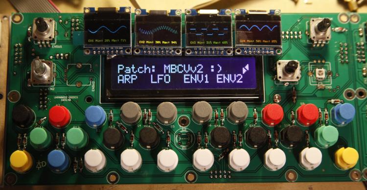
3 minutes ago, tago said:Looking at the photo it seems like you can compare the lower lines, they have the same character count (20). Around 3-4 times smaller then LCD character height. But the OLED has more vertical pixels. Maybe a condensed font is the solution to fill the whole display? Or simulate a 4x10 LCD? What looks the SCS on a 2x40 LCD, is there lots of blank space?
I think it would be possible to do a 4*20 display on a single OLED. Understand that the traditional SCS layout (visible in the MB CV control surface above) typically puts 4 buttons below the LCD to select menu items.
3 minutes ago, tago said:I want the SCS mostly for patch selection purposes in a universal synth controller. It would make sense to have a larger font on OLEDs, at least for patches names.
You're describing the Programma. 1-4 ELO boards with sets of 16 illuminated encoders and 4 "labelling" OLEDs, auxiliary SCS-OLED boards for patch name, envelope shapes, SCS button labelling etc.
-
No worries, PCBs should be here today if DHL get their act together. I have white 0.96" OLEDs on the way, could possibly try with a yellow-blue I have left.
The thing is, you don't have an ordinary button layout, so maybe traditional SCS LCD functions don't make sense anyway. But as far as the display goes, a 2*20 CLCD is 100 pixels across with a gap of ~1 pixel in between characters. So the horizontal resolution is comparable.
I chose the 6 button "hex" layout just to try something different. My thought was that there's enough space to provide two menu rows of 3 items each. Have to see though, my guess is @Hawkeye will do most of the hard work with the Programma builds ;-).
This gives an idea of how the text fits, approximately 20 characters:
-
 1
1
-
-
Not yet.
-
Here's an updated picture:
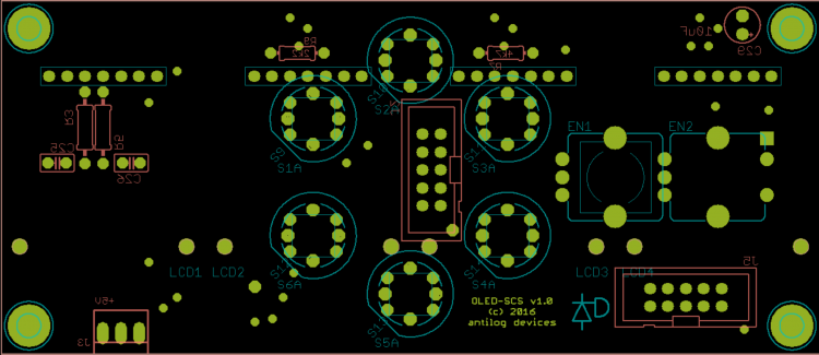
You can see 7 pin SIL rows for the displays and the six switches/encoder (two positions possible). Encoders with built-in switches are supported but you have to wire your own pins.
Possible configs are:
- OLED OLED OLED OLED
- OLED [6 buttons] OLED
- OLED OLED encoder
- OLED [6 buttons] encoder
- only switches
- only encoder
- combo of switches + encoder
- fewer OLEDs
Pinning for the OLEDs is based off J15A from the Core32F4, same for the display driver.
Pinning for the SCS is the standard J10(A).It would be possible to split the SCS functions across two boards, e.g. with OLED [buttons] OLED on one and OLED OLED encoder on the other.
-
1
-
Some cool grooves in there! Aphex Twin fan?
What's the synth/sampler setup?
-
15 minutes ago, tago said:3 hours ago, latigid on said:
You can't mix different display drivers on the same signal chain without significant re-coding. MBCV uses two separate ports and is noted as an exception. If you wished to have this coded into MBNG you'd likely have to do it yourself.
Do you know if it's possible to have say 4x 128x64 OLEDs and 1x 256x64 OLED all with the same controller chips on it in a MBNG system without customizing the code?
I don't know for certain, but at a naive guess I think you would need to program the displays with the maximum pixels in mind. So in your suggested setup you have five 256*64p displays, where the first four are only used at 50%.
-
2 hours ago, tago said:
I have seen this page, but there are only drafts/wireframes. I wanted to get a real world feel of that thing. :)
You and me both, PCB protos expected next week.
1 hour ago, tago said:Ok, regarding "MS-20 filter clones x 2 - MIDIbox CV V2" i see 4 OLEDs and one LCD. So its possible to mix displays after all? Is this only available for Midibox CV V2 or custom code?
You can't mix different display drivers on the same signal chain without significant re-coding. MBCV uses two separate ports and is noted as an exception. If you wished to have this coded into MBNG you'd likely have to do it yourself.
-
The 0.96" displays are really nice (hi-res thus sharp pixels) and really cheap. Most also have a carrier board meaning you could mount them easily. The one you found needs an FFC or 0.5mm pitch soldering, so go for the mounted option if you choose this route.
I don't think that mixing display controllers is possible without special coding (works for example on MBCV).
As far as chaining multiple displays, I know @Hawkeye implemented this for the Programma v0.1

My SCS-OLED boards will have a similar arrangement of rows of 4 OLEDs, which can be omitted in place of switches/an encoder.
-
We're all coming from different backgrounds, with different time commitments and so on. The number one priority is that the board should work, and that's the responsibility of the designer. Many other choices come down to personal preference or experience, which is totally cool seeing as we aren't under contract to provide a specific service. E.g. I will always put decoupling caps near the power pins, and if you don't believe in them (:-P) it's your choice not to populate those components.
The direction towards a casing standard is quite smart, because that's often the limiting factor in builds and can contribute majorly to the cost. @Rowan actually suggested that as a direction a little while ago, and it's very doable simply by limiting the PCB height to ~100mm. I don't agree that panel sizes should be equal to a power of two, though there is a loose idea to keep the HP values as even numbers.
It's very rational to use SMT, not just because of size and certain availability, but it allows for easier trace routing, double sided placement, closer clearance (look at the registers placed under the dot matrices above), less drill hits etc. And you'll actually find that it's easier than through hole assembly as you don't have to clip leads. Can be much cheaper for components too. Avoid SMT on parts that experience mechanical stress like pots, switches, sockets etc. Personally I stick to through hole design when I can.
Sorry for the off-topic discussion, feel free to split if needed.
-
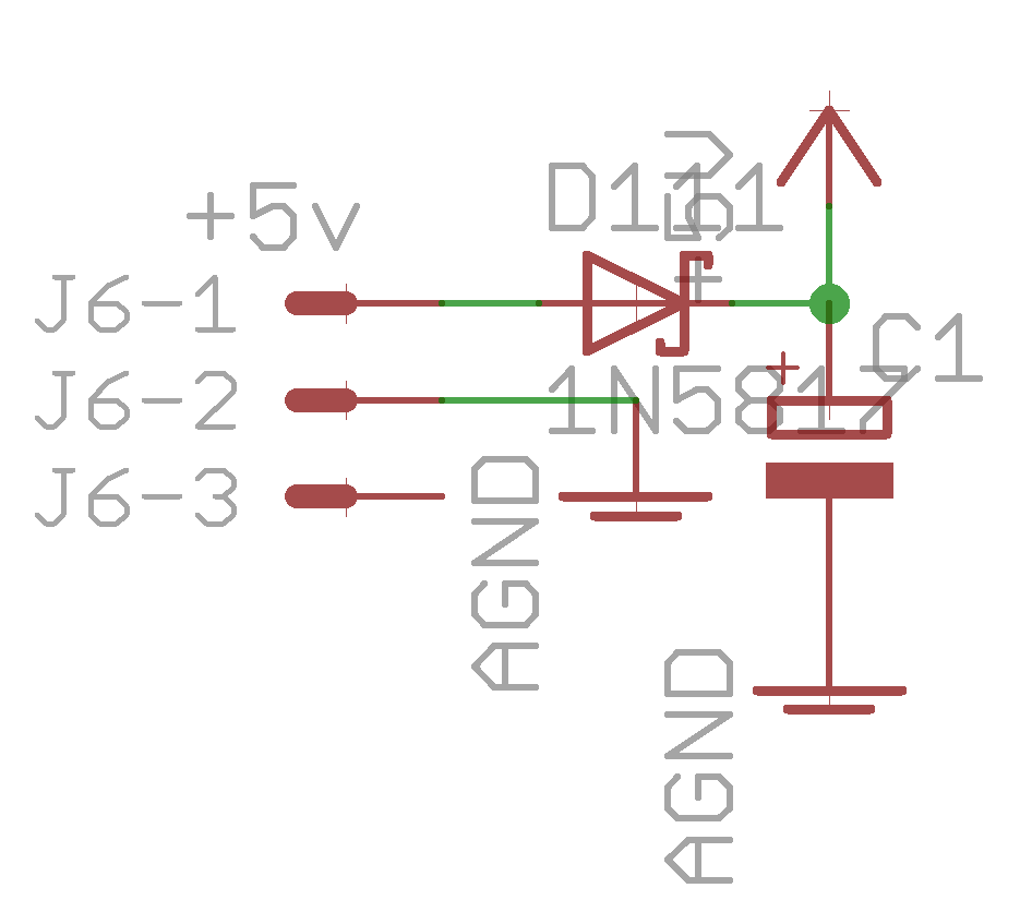
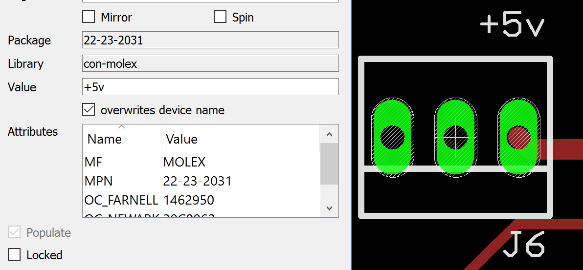
The EAGLE library part has pin 1 on the right as referenced to the schematic:

I can't say how this would relate to KiCAD, but it would be great to standardise the power connector on the right relative to the polarity tab on the bottom edge.
-
All good, here is the part:
http://www.mouser.de/ProductDetail/Molex/22-23-2031/Also available for next to nothing at Tayda:
http://www.taydaelectronics.com/connectors-sockets/wafer-housing-crimp-terminal/serie-2500-2-54mm.html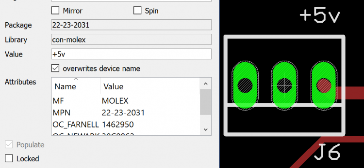
Pin 3 NC
Pin 2 0V/ground
Pin 1 +5VLots of edits today: it's of course possible to use an ordinary 100mil breakaway header in place of the Molex part.
Best,
Andy -
Quote
You need a SEQ somewhere anyway, so power will be taken from there. Adding a power supply connector just creates false hopes, I think.
If the current consumption is "high" then it makes sense to wire the power lines in
parallelEDIT: I should say "star wired." This sends the return current back to the source rather than influencing other modules in the chain. I only asked because I was wondering about the 2-pin connector at the top on the rear side. Flexibility, even if it's "over designed," can extend the device beyond its original purpose. -
Quote
Decoupling caps are highly overrated. If really paranoid you could still fly a through-hole capacitor across the IC...
I don't agree; I've read about cases where decoupling caps were the difference between a chain of serial shift registers working or not. A fly-wired cap would be just as effective as your current layout -- the closer to the power pins the better.
-
Nothing wrong with SMD, most of my upcoming modules will have some SOIC/1206. It's better to learn sooner or later.
Edit: nothing stopping @Psykhaze adding 2HP to his front panel.
TPD looks cool, but shouldn't the decoupling caps be nearer to pin 16?
Without trying to spread FUD, I wonder about lots of blinkenlights in a Euro case when potentially combined with analogue modules. Do you have any data on power supply recovery when everything's humming? It could be okay with the PSU driven from the SEQ or at least isolated from the Euro rails.
For my latest work, I include a 3-pin 100mil/2.54mm Molex header with the centre pin 0V/ground and +5V on the right when the polarity tab is at the bottom of the connector. The left pin is NC. Could we consider a standard perhaps?
-
1
-
-
Very cool, like the dub vibes!
-
Exactly, every ADC chip requires select lines. Notice AINSER64 further multiplexes the inputs with 4051 chips for a single 8 channel ADC and generates a 3-bit "address" to specify what input a 4051 should scan at a given time. This is synchronised in software to map each "pot position" with its current value.
-
How many AINs were you thinking? STM32F4 has 8 ADCs and a few of us are looking into how well this works. It's easier with known voltage maximums that you define through a resistive divider like a pot rather than CV which needs protection from over- and undervoltages etc.
-
No question, go for STM32F4. For a start, LPC17 carrier boards are not available AFAIK and they changed the pin config of the MCU breakout which further reduces the compatibility. F4 is faster, has more RAM etc.
BTW, if you only have a PIC Core at the moment, you have a SEQ V3 :). Perhaps you meant STM32F1, the first gen. Core32?


Follower of STM32F4?
in MIDIbox NG
Posted
Hi Zam,
Okay, is the D variant working whilst plugged into a computer or standalone?
Best,