-
Posts
1,483 -
Joined
-
Last visited
-
Days Won
10
Content Type
Profiles
Forums
Blogs
Gallery
Posts posted by jojjelito
-
-
The box arrived safe and sound in order today.
Thanks for your efforts and the time you spent doing this Martin!
Cheers
Johan
-
There's some talk about these at Mutable Instruments now, so I don't think there will be any leftovers. Hopefully TK should be able to sell the entire stash pretty soon

-
Exactly!
There are specialized rotary switches with a fixed number of stops, then we have things like the Lorlin switches where you can set the number of stops by moving an internal stop part. The switch may be 1Px12, 2Px6 or 3Px4 and you can set it to the number of stops desired.
-
Just waiting for the bank transfer to go through :sorcerer: Guess PayPal is faster, but I can wait a while as the SEPA payment saved some € in fees. No stress, then I guess I need to bulk buy components :frantics: Wonder when the backlog reaches critical mass?
-
Thank you! Thank you! Thank you!
Now it's just some transit time before I get my paws on these to be illuminated knobs :thumbsup:
-
Take a look at the old revisions of that Wiki page - it's still there a couple of revisions back.
You were at:
artyman 0 0 1, so I guess you only wanted one GM5x5x5 PCB.
-
No, your proposal is sound in theory. However, you need to check if the DAC itself is designed for uni- or bipolar operation, if there's a reference that needs to be applied etc. I haven't studied the MAX525 in detail, but some checking would be prudent.
-
Cool! You're getting it! Congrats

A+5 going one way, A-5 going the other. Simple

-
Basically the op-amp offset is the error voltage when the input voltage difference is zero you expect the output to be zero. That is not the case as the transistors inside the op-amp aren't perfectly balanced. Here's an explanation. You can either use external trimming, or the op-amp is trimmed at the factory. There are some low-offset op-amps, for instance it might be a good idea to use TL082/084 for CVs instead of 072/074 (which are generally better for audio) since the 08x has lower offset. Anyway, the error is usally very small but one should be aware that it exists and that there are ways to mitigate it if necessary.
The gain-bandwidth product is basically telling you something like x Mhz from the datasheet. For the TL08x it's min 2.5MHz, typ 4.0 Mhz. It's typically 3.0MHz for TL074. The 074 is less noisy though so it's usally preferred for audio. OK, what does this mean?
Let's say you need to make sure that an AC signal of 100kHz can be amplified without too much distortion. In this case you can amplify up to 25-40x before you lose signal integrity. More for a signal of lower bandwidth.
In the example with the CV mixer we have a gain of 1. A signal of 2.4 to 4.0MHz will pass trough. Good enough for audio, less so for analog SD video.
All in all, I would take a look at the offset (which is likely to be small), I don't need to worry about the gain-bandwidth in this application since we don't amplify and don't have a high-frequency signal to worry about.
-
Don't get me wrong; I'm very grateful that you provide input, but according to the stuff I read yesterday the voltage clamp is not complicated at all, and it uses less parts than your suggestion :wink:
Look at this picture: http://en.wikipedia....lamp.svg&page=1
I see one opamp, two resistors, a diode and a capacitor. Or am I missing something?
No, the less parts (marginal, it's only a couple of resistors) is fine. Less parts is always nice.

But, please run a Spice or similar simulation of this (iCircuit or...) and you'll see the effect of the RC constant. Also, I don't think the clamp is OK with slowly changing or more or less constant DC voltages due to the influence of that RC element. It introduces a frequency dependency that might affect any FM or lag or constant voltage CV. The mixer won't exhibit those effects. You might even want to breadboard those circuits for checking.
For the mixer you only need to worry about op-amp offset (a small problem) plus the bandwidth product of the op-amp.

Have fun!
-
Knobulation!
Now I just need to buy a ton of encoders and other panel hardware

PG-990? PG-300 clone? PG-5080? K5000s knob box? Fs1r knob box - needs to be bigger than a football field...

-
Yes, I found that a "Positive voltage clamp circuit using an opamp" is what we want; this will act as a voltage doubler and force the signal at or above 0v. The opamp part is because is introduces percision over the standard diode clamp, which suffers from the voltage drop of the diode.
Again a bit of theoretical knowledge without knowing the how to apply it in practice. Wikipedia has an article about it but I still don't know which value of components to choose :pinch:
Link to the article: http://en.wikipedia....er_(electronics)
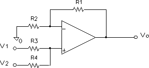
Errm, I think that's over-complicating things. Why not just use an non-inverting mixer where you add or subtract 5V?
You can use a stable precision +-5V reference if you're really picky, but that's overkill IMHO.
Something like:
CV In->100k (R3)
5V offset->100k (R4)
R2=100k
100k (R1) plus 22pf cap across (in parallel) to prevent oscillation in the feedback connection

vo =v1 + v2 (for all resistors equal)
vo = (R1+R2)/R2 (v1 R4 + v2R3)/ (R3+R4)
This makes -5V become 0V, +5V becomes +10.
By adding a -5V you can go the other way.
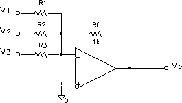
Or, you can use an inverting mixer plus a unity gain inverting op-amp to make this less impedance sensitive at the cost of more op-amps used.
This makes the circuit look like this:

followed by a standard inverting op amp.
-
The rabbit hole goes a bit deeper: The Yamaha CS series also use Hz/V as well as the old monophonic preset boxes Yamaha SY-1 (needs added sockets) and SY-2. Then you have the exotic stuff like Buchla that uses 1.2V/Oct. All of that won't have much bearing to you maybe, but there's weird gear out there for sure... :sorcerer:
However, uni- to bi-polar: Can't you just add or subtract an offset depending on which way you convert? The slope at 1V/Oct should be the same no matter what.
-
I'll take 1 MB6582 window.
-
Thanks for hooking us up kind sir!

-
Same thing usually.
Knurled shaft:

Splined shaft:

Sometimes you also see serrated shaft, or T18.
-
Sounds fair. I'm pretty sure I'll have one of those, with Molex plug. You can add mine to jojjelito's box and we'll split the shipping. Right, jojjelito? :)
Sounds like a plan. Paying more for postage for something that's destined just a couple of km away isn't economically sound.

-
There's no shortage of Re'an knobs over at Rapid in the UK as long as you're looking for P670, P300, P570 and P861 with various caps. They also have a good selection of Sifam knobs. All of this is for splined T18 shafts though.
-
OK,
I'll settle for one PSU with connectors please.
Cheers!
-
Happy birthday to Schrabikus!
 One of the real Mc Gyvers out there.
 -
Ouch! There's only 7 people with my last name in Sweden :D Plus a couple more world-wide.
As long as your name isn't common with something on the terror list like that 4month baby who got denied to fly recently...
-
I definately think there is demand. I advertised the goodness that springs from the GM5 IC around at Mutable Instruments, and this is what filled the list with takers. Others, like Altitude testified to the fact that the interface is really good, stable and fast. I have some extra GM5x5x5 PCBs, but that's why I ordered more ICs than boards this time around. It shouldn't be a problem to sell both the mini-PCBs for Shruthis, Ambikas, and other DIY synths and such as well as shifting the 30 odd existing 5x5x5 PCBs and more

Cheers,
Reckless youth in Stockholm
-
Hi Antonio,
I could spare you a couple
 Both ICs and PCBs. There's also 4 dummy ICs...
 -
Great news! Thanks TK


Thank you SmashTV
in Miscellaneous
Posted
I'm with Herr Hawkeye above! SmashTV is a miracle worker! Thanks! :super: