fussylizard
-
Posts
280 -
Joined
-
Last visited
Content Type
Profiles
Forums
Blogs
Gallery
Everything posted by fussylizard
-
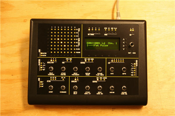
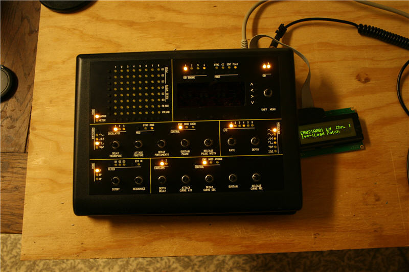
Scratch that last part about the pots. I drilled out the feedback pot holes to .316" and was test fitting the first one when I realized that the pots are too big for the rear-panel hole spacing (back part of pots are too wide) so I can't fit adjacent pots on the back panel. Duh. So I'll have to order new pots. I'll probably just put in two temporarily to see which I prefer (500k or 100k; audio vs. linear). Not a big deal, but a bit irritating. At any rate, I only have a few things remaining and I'm at that dangerous point where things are functional and motivation to finish off the last details wanes rapidly. :-) My biggest concern at this point is the heat that the SIDs generate, so I'll at a minimum cut some ventilation slots similar to Wilba (or maybe just drill holes, that would be much easier) to increase airflow. If I can find suitable heat sinks I'll use those as well just to be safe or I could try making some on my milling machine (that might be fun!). I need to post pics of the way I mounted the front panel to the case. After my copious amounts of JB Weld on my corner bolts it seemed unlikely that "countersinking" the mounting holes in the case would leave much plastic left. I ended up cutting the corner mounts out completely with a hobby saw. I then put the panel in the front part of the case and then used large-ish washers to hold the front panel to the backside of the case. I still had to file down part of the ledge that supports the front panel near a couple corners due to JB Weld, but everything seems solid so far. I'll probably JB Weld the washers in place to preclude slipping just in case, but it's probably fine w/out it. I used two nuts with a lock washer in between them to hold the washer in place without putting undue pressure on the front panel. Pity I didn't take pic of the final assembly, but I'll do so when/if I mount a clear window in front of the LCD. So here's a pic of where things stand. I'm pretty happy w/ the LED brightness, though they barely show up in the pic. It is a huge improvement. Can't wait for the knobs from the bulk order...
-
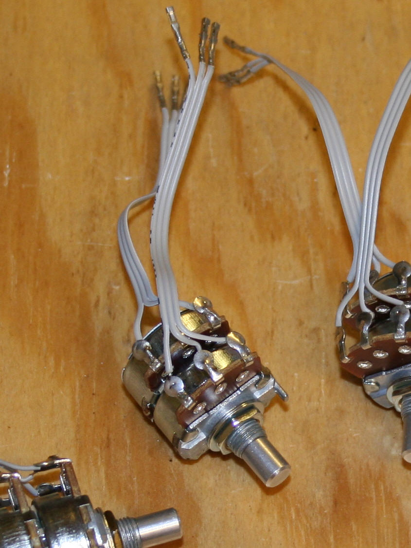
@Wilba- thx for the info. I ended up getting 24mm pots, which probably explains it. Nothing a drill bit can't fix though! BTW did your pots have little metal posts that stick out the same direction as the shaft (see pic), presumably for going into a second hole in a panel to keep the pot from rotating when you turn it? If so, did you leave it on or grind it off?
-
Looks like you had it oriented correctly, flat side toward the back of the board (facing the power switch)...
-
@strophlex - Cool, I'll have to give that a shot. Project update: I finally got some more time to work on stuff last night, so here's where things are: - I fiddled about with new resistor values for the CS LEDs and determined that 2200 Ohms are what the doctor ordered (instead of the stock 220 Ohm with SmashTV's kit). I tested with the original 220 Ohm resistors and thought they would be fine (and, let's be honest here, I was perhaps just the slightest bit impatient and wanted to see the pretty lights working), but once things were closer to finished they were way too bright. The new resistors make the LEDs almost dim, but I compared the brightness to other equipment I have and tried to match that. I can now read the text legends easily even with several lights on nearby. So my advice on LED brightness is to compare to other equipment if possible since the best brightness will probably be way less than you initially think. Way less. - Desoldering the old resistors was a barrel of fun. I tried to salvage the old resistors by cutting one leg from the top side and pulling them out from the top while heating the bottom. Unfortunately I ripped up a trace (!) on one of them. I got lucky in that it didn't detach from the pad at the other end, so I was able to just solder the other end back down with the new resistor and it works fine (you can barely tell it was messed up). So for the rest of the resistors I followed Wilba's instructions exactly and cut each one in half, heated the bottom while pulling the part off from top of board, and then used a solder sucker from the bottom while heating from top. A solder braid helped with a few problematic holes, but it went pretty smoothly after I cut the parts in half. Thanks Wilba for the recommendations! - Turned out I had 15 2.2K resistors in my scrap box, one short of the 16 needed. I popped by Radio Shack earlier today and they had 2.2K 1/8 watt resistors. The others are 1/4 watt, but by my calculations the 1/8 watt will be fine so I can live with having one physically smaller resistor. - I re-glued the corner bolts using way more JB-Weld than last time. Hopefully that will hold better now. - I soldered wires and crimped headers for the feedback pots. I have two 500k audio taper and two 100k linear taper pots. I'll try them and see which I prefer. I also discovered that the rear panel holes are too small for my pots, so I'll have to drill them out like I did for the power LED. (I guess parts in Australia are smaller, Wilba? :-) - I need to figure out how to attach the power LED. My plan is to just glue it to the back of the hole, but if anyone else has a better idea feel free to pipe up. I'll upload some pics later. Regards, C
-
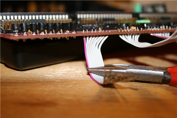
I only used RA headers on the top of the CS PCB. I soldered the cable to the baseboard as shown in the pics here: http://www.midibox.org/forum/index.php/topic,13492.msg116408.html#msg116408 There really isn't much space in the bottom part of the case for RA headers on the baseboard (they *might* fit, but it would be tight) but ultimately you really only need one side detachable so I just put the RA headers on the CS. I'm going to have to re-glue the corner screws sometime this weekend, and this time I'll use a lot more JB Weld. I didn't have to hollow out the holes before, but this time I definitely will. :-)
-
Midibox SID keeps formatting, rebooting, formatting, rebooting...
fussylizard replied to djvinz's topic in MIDIbox SID
Are you using PCBs/kits from SmashTV or are these your own boards or what? Since this happens w/out the banksticks attached, it sounds like there might be a wiring/soldering problem with J4 on the core (the bankstick interface). I'd check for shorts, etc. on those four connections. I don't know how the FW detects banksticks, but if the SC or SD pins are shorted to Gnd or +5 that might be the problem (a guess). FWIW I was just looking at the core schematic and the way it is drawn is sort of odd. It shows SC on J4 with a red line saying "Pin #28 of PIC". I guess that means it gets connected to pin 28, but that seems sort of weird since that pin is going to J15 already. You may already have this sorted out, but I would double check on that if you're making your own board or something. If you got boards from SmashTV they should be fine in which case I'd focus on shorts. HTH... -
I take it all back. I got my LCD installed to the board and was screwing the case together with the bottom screws when one of the corner screws detached from the back of my front panel. Once I figured out what was going on I discovered another one (opposite corner) was loose, and I yanked a bit on another and it came off also. The fourth one is still solid. So...I guess I'll have to try sanding the panel and using more JB-Weld. One downside to using right-angle headers is the wires get pretty bunched up and can make it a little hard to close the case. The wires have to be long enough to allow you to open it up flat, so I don't know that there is much to be done about it. But I can't imagine not being able to detach the boards from each other without desoldering, so I'm still glad I did it. One step forward and two steps back tonight... :-(
-
You might be able to run an original C64 tracker in an emulator that supports hardware SIDs and get some mileage out of that. It appears that VICE has support for hardware SIDs. Also I think I've read that MIDIBox SID supports the ASID protocol (though I've not seen instructions on how to use this or set this up, but I've not really looked into it yet). I'm getting close to finishing my MB-6582 and I'm interested in playing .SID files through it so I may look into this in the next few weeks.
-
Good idea! I guess 2-3 layers are required (not sure of the thickness) to close the gap?
-
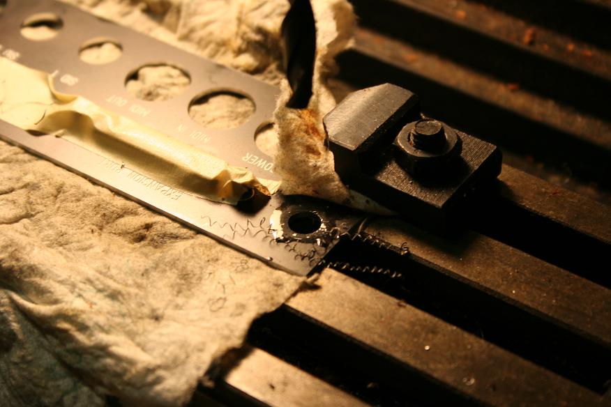
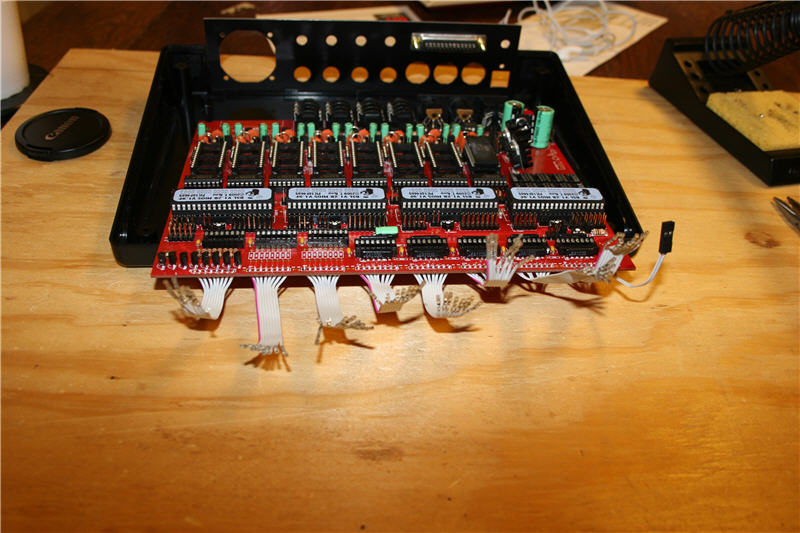
@Wilba - Well I'm having tons of fun with it. This truly is a great community. I've kept a few notes along the way so hopefully I can contribute some pics and improved documentation. So what do you get at 2000 posts? :-) Quick update: I indeed still had the testtone app on cores 2 and 3, so after uploading the MB-SID app all four cores are working. I also enlarged the passive audio out hole to fit my jack w/ a size O drill bit (.316") - see pic below. I have a small milling machine so it was super easy. I also installed the fan I bought from Mouser. It's super quiet so I'm pretty happy w/ it. I played about w/ the CS and I think my LEDs are too bright. Pity since I'll have to de-solder the resistors I put in the other day. I may just solder in sockets so I can try different resistors to find the ideal brightness. Glad I kept that assortment bag of resistors I bought from Radio Shack back in, oh, 1985. Better sand those leads a bit to remove any oxidation before I use them... NB #1 - the encoders are a bit difficult to turn w/out knobs. Can't wait for those to arrive from Goblinz's bulk order. NB #2 - it's also hard to use the softkeys below the display when the display is not mounted and sitting off to the side. :-) I should get my LCD mounting bolts tomorrow, woohoo! I've been surprised at how the pins for the headers to my CS have not managed to short themselves despite not having the black female sockets yet. I was a bit concerned about it, but they seem to have stayed fairly well aligned despite opening and closing the case dozens of times. See pic. Also, my SIDs get way hotter than I'd like. There was a recent thread about heat that I'll have to re-read, but mine are NOT comfortable to touch for more than a few seconds. Hopefully this is normal, but I'll probably look into getting some sort of heat sinks if possible, esp. since replacements will be scarce since Wilba haz no moar SIDz (though I did get two spares just to be safe). Hmm, 3mm acrylic windows might work well. Where would one get such a thing? A plastic supply store?

-
My post count hit 50 so I became a "MIDIBox Member" and got a second star by my name... <proudly wipes tear from eye> I love you guys.
-
Glad I read this thread since I probably would have had the same problem w/ the upload in a day or two. :-) Weird w/ the sequencing issue. I would attack this by trying to get as simple a test case as possible that is reproducible (i.e. the simplest sequenced clip that gets it to fail repeatedly), then try to duplicate it by playing the same sequence yourself. Then you can look at the MIDI messages w/ MIDI-OX or something to figure out what's different assuming it works fine when you play it manually. So does it happen with all sequenced patterns (i.e. try a pattern w/ a single quarter note each bar and another pattern with 16th notes each bar), or does it depend on how fast the notes are played, etc.?
-
This probably won't help, but you can always add the code / HW yourself. Anything is possible given enough time, $, and skill. :-) Most implementations I've seen of something similar (on commercial synths) have an internal clock mode for when you don't have an external source, and and external mode for when you do. So you'd probably have to consider both cases if you do it yourself.
-
@strophlex - Looks good! I didn't see your post earlier since it wasn't in the MIDIBox SID forum. Thanks for the link! @wilba - the display is a CrystalFontz CFAH2004A-YTI-JT - https://www.crystalfontz.com/product/CFAH2004AYTIJT.html I used a 2x20 version on something else and really liked it, so I decided to get the 4x20 version. You can get cheaper displays elsewhere, but I've been happy with the CF ones so I've stuck with them. @m00dawg - yeah, the lighting is off, sorry! At full power the LEDs are similar to the yellow display, but as part of the CS they are much more orange. I'm not sure if reducing the resistors used to ground the LED matrices would change the color or not. The resistors are only 220 ohm IIRC, so there's not much to reduce. It's probably the 1/8 duty cycle that's the issue, but I'd have to test to find out for sure.
-
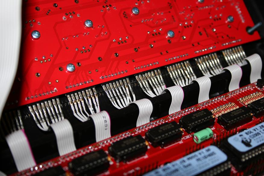
Nice! The red theme reminds me of an Access Virus. Did you use .100 spacing cable to connect the PCBs? If so, where did you get it? I couldn't find it at Mouser (it's there somewhere I'm sure) so I just used standard IDC cable. Thx again re: the 8-pin connectors.
-
Wow, thanks for the offer, but I got impatient and ordered some from Smash over the weekend so I think I'm good. I ordered a bunch of various sizes ages ago, but that was before he carried the 8-pin ones. I really appreciate the offer though, thanks!
-
Here's a few pics, including the top panel showing the orange-ish hue of my yellow LEDs. I also included two pics of the base PCB wiring that goes to the right-angle male SIL strips. Amazingly I didn't take a picture of the CS side of things. I'll have to do that the next time I get a chance to work on it. The standard IDC cable works fine so far, and the convenience of the detachable CS from the base is nice.
-
I used standard IDC cable since that's what I had, and I couldn't find the other stuff on Mouser (I'm sure it's there, but I just couldn't find it). The standard IDC cable seems fine to me. I soldered the right-angle header strips to the top of the CS, and soldered the cable to the bottom of the base PCB. It worked pretty well. There is sufficient room between the top case and the right-angle connectors for the headers to be slid on/off without having to unscrew the CS from the front panel. I'll post some pics when I get home.
-
FWIW My screws stick great to the FPE panel I got. Those things are never coming off. I think the threaded shaft would break off before the head came unstuck.
-
It's probably not much better than putting it on the panel directly and then clamping, but it does relieve some of the stress of trying to clamp quickly. I think the standard JB Weld takes a while to set, so it's probably irrelevant. BTW A quick update on my panel- my CS is pretty much done. I tested the encoders and they all work now. I messed up a via on the base board a while back which broke one of the encoder inputs, but I bypassed the via with a wire so it works great now. Now I just need to solder the encoder tabs. I was a little disappointed that my yellow LEDs look more amber on my panel than I had hoped. At full power they are very yellow, but on the CS the PICs only power them 1/8 the time (per my understanding of the display matrix) which is probably the issue. It's not a big deal, but I was hoping for pure yellow. On the up side, I tested the stock resistors for the LEDs and the LEDs had a good brightness, so I soldered them in. I have been unsuccessful in finding bolts/washers/nuts for the 2.5mm holes to mount the LCD, so I ordered some from McMaster-Carr last night. Hopefully I'll have the LCD mounted mid-week. I decided to use right-angle connector SIL strips for the CS to base board connection. I didn't like the crimp pins I got from Mouser for the SIL headers that are needed to connect the CS to the base board. I had some pins from SmashTV sitting around that worked much better, and he now carries 8-pin female headers. I went ahead and crimped all 66 pins over the weekend and hooked up the CS without headers (being careful not to short the pins together when moving the CS). It worked well enough, and I ordered the necessary headers last night (along with the other headers I forgot about initially for the feedback pots...I already had spares for the fan, passive audio out, etc.) Now I just have to hope the 8-pin headers that SmashTV sells are the same as the other sizes or else I'm going to have to re-crimp all those connectors. :-) I also discovered that that the passive audio output jack I bought is slightly too big for the rear-panel hole. I'm probably going to just drill out the hole in the panel so it will fit (I have a small metal shop at home) instead of finding a smaller jack. The exciting part last night was finally mounting the 6582 SIDs I got from Wilba (!). They replaced the single 6581 I had been using. Unfortunately I discovered that CORE2 and CORE3 are not responding (I get a "no MBNet connection" message when selecting those cores). I also get a steady tone on the passive mix that sounds eerily like a 1Khz triangle tone. I'm guessing I forgot to upload the MB-SID firmware to those cores (they are probably running the testtone app), but it was late so I didn't have time to mess w/ it last night. Anyway, I'll post pics of the CS tonight with the lights and all. Getting close! Regards, C
-
Don't forget to check power (incoming and at each IC) and verify the ICs are inserted correctly.
-
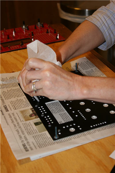
I'm sure it will be perfect! I was a bit apprehensive about all the JB Welding, but it was fairly straightforward. Now how are your cake icing skills for the next step? :-)
-
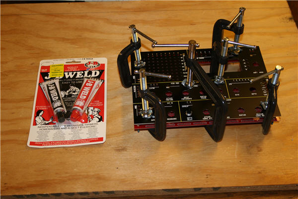
As promised, here's a pic of my wife (a former pastry cook), using some parchment paper to pipe out JB Weld onto my panel like cake icing. :-)
-
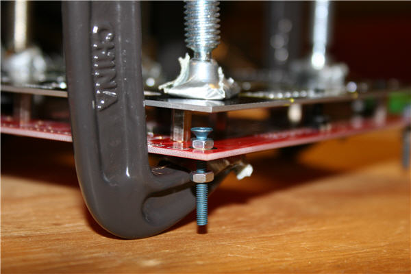
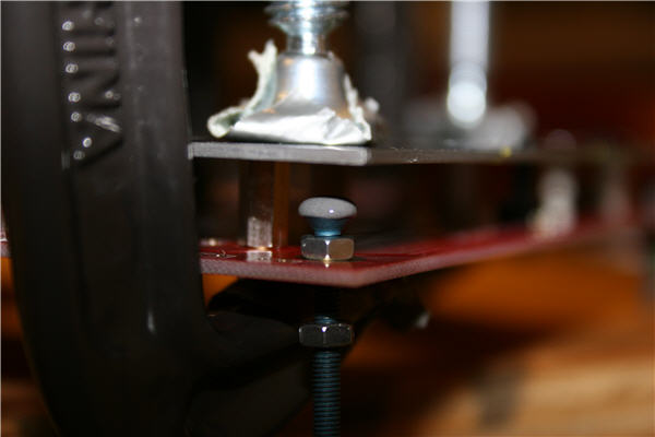
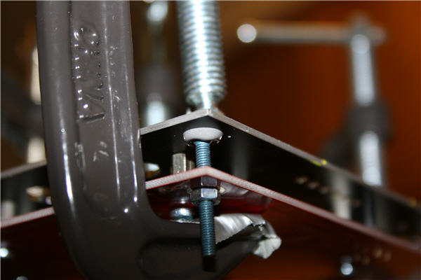
Here's what worked for me. I first clamped everything and left it panel-side up. I attached the bolts in the corners with two nuts, one above and one below the PCB. Then I put a small blob of JB-Weld on top of the bolt head (since the bolt head was facing up, towards the back of the panel) using a flat toothpick (there's not a ton of space to maneuver in there, but just get a small blob on the top of the bolt and spin the bolt against the toothpick to break off the sticky, stringy "tail" of JB Weld, sort of like you would do with a fork and pasta). Then I twisted the bolt to raise it to the back of the panel and tightened the nuts to hold it in place. Once all four were done, I flipped it back over. Easy as pie. I dragged some pics off my camera showing the process. HTH, C BTW - I hope you ordered bolts to mount the LCD in your McMaster order. They are 2.5mm holes, and Home Depot only carries down to 4mm metric and #4 standard (which is 2.8mm - too big!). So...I'll probably have to order some from McMaster-Carr. I also failed to get screws to hold the PCB into the bottom of the case, so I'll need something for that also.
-
Purdy!