fussylizard
-
Posts
280 -
Joined
-
Last visited
Content Type
Profiles
Forums
Blogs
Gallery
Everything posted by fussylizard
-
That's what I mostly ended up doing last night. With a working crimp tool making those connectors is not a big deal. With needle-nose pliers it's downright tedious, esp. when I need to crimp 66 pins. I realized I have enough crimp pins from SmashTV to do what I need to do, but I don't have any 8-position female headers. So I'll probably just use SmashTV pins bare for now (without headers) and order the headers the next time I place an order with SmashTV.
-
I just finished soldering the control surface board last night. As long as you take your time on the JB Weld and soldering, it's pretty straightforward. Wilba's instructions were spot-on. FYI I discovered last night that the 3mm bolts that are used for the threaded standoffs are too big for the holes in the board for attaching the LCD. I'll have to dig around in my scrap box for smaller bolts (2mm?) or buy some at Home Depot to attach the LCD. Can't wait to see the pics of your panel. Mine's looking pretty nice w/ the yellow LEDs and the yellow lines...pic soon.
-
I found what I thought were similar ones on Mouser (8 position - 538-50-57-9008 for header and 538-16-02-0096 for pins). Last night I searched the forum and found a post that recommended this same line of parts - http://www.midibox.org/forum/index.php/topic,8498.msg59492.html#msg59492. However, I tried crimping them last night and they were a huge pain and didn't really work with the crimp tool I have. Mouser lists hand crimp tools for these for $300+ (!). The pins from SmashTV crimp perfectly with the $11 crimp tool I got from CuriousInventor. If anyone has had success crimping these pins from Mouser without the $300 tool I'd love to hear about it. As an aside, I saw last night that SmashTV now has 8-position headers (I swear they were not there a month or two ago or I would have ordered them from there in the first place). I'll give the Mouser pins one more shot this weekend but I'll probably end up just ordering some new ones from SmashTV that are easier to work with. Regards, C
-
Just for posterity, in the US you can get a crimp tool from CuriousInventor.com for $10.99 + shipping. Works great w/ pins and headers from SmashTV. It's definitely worth it.
-
Just a quick followup to close out this thread. I ordered a new PIC from SmashTV (got it last week but have not tried it yet). However, SmashTV saw this thread and insisted on replacing the dead PIC at no cost and sent me a refund. So I just wanted to let folks know that SmashTV really has gone the extra mile here which just further confirms my complete confidence in his products and services. Now hopefully tonight I'll have some time to check out the new PIC... Thanks again Tim!
-
Wow, great news that it's working! I may have the same problem with the note being held on my 6581 from my old C-128. I'm not sure if that is normal or what. I've not looked into it yet to see if it's a SID problem, etc. I'll watch this space to see if anything comes up. :-) I have 6582 SIDs on the way from Wilba anyway so for me it's probably a moot point, but I might run 6581s off one core of my MB-6582.
-
You get a tone without a SID because the PIC generates a 1Khz triangle wave signal straight to the /CS line (bypassing other chips). When you connect /CS to the output pin in the SID socket with a wire the 1 Khz tone goes straight to the output buffer circuit, giving you a tone. That tone sure is loud though. I had headphones plugged into the output jack (not wearing them, thankfully!) and right before I powered it up I worried that I might not hear the tone, etc. Well, no worries there. For newbies out there, if you are not sure if you can hear the tone or not, it's not working. :-) I'm not sure how the test tone works w/ a SID, but the readme suggests it goes through the 74HC595 chips so if you get a tone with the SID installed, your 74HC595 chips are probably OK. It makes sense that the interconnect test would work with the /CS pin since it comes straight from the PIC and bypasses the 74HC595 chips. For the interconnect, did you connect the MD pin (you did not include it in your list)? I've not built the standalone modules, but from the schematics and interconnect diagram everything else looks OK per your list other than the missing MD. You should have 7 wires going into J2 on the SID board (or 8 if you connected up the unused SC signal). BTW It looks like you can grab power (VS and VD) from the J10 Core connector instead of J2, but the way you have it w/ J2 should be fine.
-
Yeah, those look like the item. I'd found them at Mouser, so I hadn't even bothered checking M-C. M-C is great, I've ordered tons of stuff from them over the years. If you're mounting a fan you might consider getting M3 bolts for mounting it. (You can then use the nuts and washers leftover from the other parts in the order list.) The bolts in the parts list I gave above look sort of weird for this purpose (they are blue-ish to help us Texans remember these are "strange" metric bolts instead of normal, "American" bolts, LOL!), whereas I'd prefer a chromed/zinc look to match the fan guard, and probably a normal pan head instead of the countersunk head. I'm sure M-C has them somewhere. I probably have some bolts that will work in the disaster area known loosely as my shop. I'm pretty sure I can mount the LCD using extra bolts/washers/nuts from my M-C order, so I should be good there. I'm trying to keep track of all the extra parts needed for future reference. I have some work to do today, but I'm hoping to start soldering the control surface today. I got all the JB Welding done Wednesday and Thursday, so I'm ready to solder. BTW, did I mention how helpful it is to have a wife that's a former pastry cook? She piped all 23 of my JB Weld blobs out like icing in about 2 minutes. :-) I'll have to get the pics off my camera and upload. POIDH, right? Maybe Wilba can add this as the standard way to create blobs of JB Weld on the control surface. :-)
-
Tips for cutting ventilation slots in a PAC-10 case?
fussylizard replied to fussylizard's topic in MIDIbox SID
Cool, thanks. Good thing I have a Dremel tool! -
I noticed Wilba's MB-6582 had some nice uniform-looking slots on the right side of the bottom half of the case, and I'm sure other folks have some good methods for doing a professional-looking job of this. Any suggestions appreciated! Thx, C
-
Goblinz - Thanks for all the effort on the bulk order, I really appreciate it!
-
Great that you got full power! Yea! When I got that 1Khz testtone myself I was ecstatic. Did the testtone app work both without a SID (bridging pins 8 and 27 with a wire) and with a SID in? For the interconnect app test between pin 14 on the SID (ground) and the pin displayed on the display (i.e. A0 = pin 9). The selected pin should be +5V when selected with the mod wheel and 0V otherwise. The /CS pin (pin 8) is the opposite, and should show 0V when selected and +5V otherwise. You might have to take the SID chip out when you test this (that's how I tested mine). If you don't have the expected voltages then start by verifying the two 74HC595 chips on the SID board are getting correct power (pin 8 = ground, pin 16 = +5V). Good luck! C
-
Nice! Can't wait to finish mine!
-
I ordered most from McMaster-Carr (the first # is the M-C part #): 92925A023 25x countersunk bolts 90591A121 100x M3 nuts 92005A116 100x M3x6mm bolts 91111A118 100x M3 lock (spring) washers 91100A120 100x M3 washers 7605A11 JB Weld 13.61 + shipping There are pack sizes of 25x and 100x for the above parts so I have plenty of extras. It would probably be cheaper to just order it in bulk from M-C than buy it at a hardware store. M-C is cheap and fast but all this stuff is probably available at HD or Lowe's. However, you do need spacers (~25) and I doubt they will have these at HD or Lowe's. I got mine from Mouser along with the zillion other parts I ordered for the front panel: 855-R30-1001002 Metric Spacers M3 x 10mm THREAD HEX BRASS 5mm A/F Unfortunately these are backordered at Mouser now. I bought some extra so if you get desperate I can mail you a set. You could also try Digikey. I didn't buy anything specific for mounting the fan or the LCD, but I think I can use stuff from the above parts list for this...watch this space. :-) Once I've finished and verified everything I bought works I'll post my parts lists so others won't have to spend as much time as I did trawling mouser.com and mcmaster.com. Regards, C
-
Gah!!! I spent an extra $5.98 by going with the medium option instead of the cheap option?! Argh! :-) It took me a while to pick through the three files so I'm surprised I didn't notice that the cheaper one would have worked. At any rate, the panel came out perfect, so I have no complaints. BTW I JB-Welded the four corner bolts last night. Went pretty smoothly and everything is looking good this morning. I picked up 9 x 2" clamps yesterday which made the process super easy. Hopefully I can get the spacers glued tonight, and then I can start soldering the CS tomorrow night! Regards, C
-
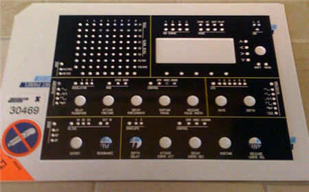
Not much to show since I haven't built the control surface yet, but here's an image of the front panel. The plan is for yellow LEDs, yellow display, gray Albs knobs. For some reason the gray + yellow makes me think of a neoprene wet suit, but hopefully it will look good on my MB-6582. :-) BTW Wilba just posted my SIDs (thanks!), so I'm getting close. Now I'm just awaiting my knobs from the bulk order and I'll have all my parts. Hopefully I can build the frontpanel this weekend and try everything out with my one 6581. Work's been killing me lately, so I've not even had time to start the JB Welding on the panels yet... :-( Regards, C
-
@NILS It took me a minute to look at it, but I'm guessing that on the right is a bankstick RAM chip soldered/attached directly to a 4-pin female SIL socket? Nice.
-
@Wilba - I wanted yellow lines to separate each section to match my yellow LEDs and display. I couldn't do it with the cheap option since it uses a single pen, and I didn't need the flexibility of the expensive option. Here was my impression of the options after playing with FPE: - Use the cheap option if you like the panel as-is or want to change the color of everything (all text, lines, etc.). You can add additional elements as desired. - Use the medium-priced option if you want to change the colors or engraving widths of each type of element (i.e. make all the text red, make all the section dividing lines a different color/width, etc.). You can add additional elements as desired. - Use the expensive option if you want any of the above plus the ability to change text and graphics used, delete individual lines, etc. You can add additional elements as desired. - You can also make a panel from scratch and do it however you want. It's interesting that the same design rendered via HPGL is cheaper than when the elements are placed separately in FPE... @m00dawg - I'm in Austin and I placed my order on Sunday April 19. The panels shipped on April 28 using their standard (no rush) service. They arrived on May 4 via UPS. I have no idea if the April 19 - 28 time is standard manufacturing time or if it is sometimes slower or faster with their normal service. I'm 100% happy with the panels, so if the $ are not a limiting factor I can't see going anywhere else.
-
I'm sure this has been said a zillion times before, but I just got my panels from Front Panel Express for my MB-6582. Perhaps not the cheapest option (US$150 shipped to my door in Texas), but they are a pro operation all the way. Perfectly packed (including a hand-signed thank-you note with a pack of gummi bears included LOL) and more importantly, perfectly manufactured 1.5mm thick panels. Highly recommended! (FWIW I did the "medium priced" option on the front panel and the "cheap" option on the rear panel.) Regards, C
-
I just pulled a 6581 out of my ancient C=128 and it had thermal paste and a connection to the overall heat "shield" that goes across the whole board. I tested the SID in my MB-6582 I'm building and it was getting pretty warm. Voltages all tested out so I will probably add a heat sink to it unless the 6582s run much cooler. I just checked my C=64C and it also has the heat shield with thermal paste to the SID. HTH, C
-
I ran the changeid application and it worked great. Of course I don't have the control surface built yet so I can't really do much w/ it. I did use the MBSID editor and verified that all oscillators and the filter work on my pulled 6581, so that was great!
-
Just took a quick peek at the changeid readme on my lunch break. TK conveniently supplied a ready-to-load .hex file for the change, woohoo!
-
No, thank you for the help and the sanity check. I know how irritating it can be to remotely debug stuff, so you must have quite a high level of patience with all the questions you get. :-) I'll check the label just in case, good idea. SmashTV is uncannily thorough so it is unlikely that is the issue but anything is possible. One of the two dead pins initially worked so I suspect it is somehow my fault. I'll try the change ID app, thanks for the suggestion. I figured the master had to be PIC 0, but I've not picked through the docs that far yet. I built a PIC burner a while back that will probably support the '4685 so in the worst case I can always fall back to that. Beer will be on its way shortly... Thx, C
-
Update: I re-tested some stuff as described below using Wilba's nomenclature for PICs vs COREs (makes this much easier to describe, thx!). Here's where I am: Uploaded SID interconnect app, one PIC at a time slotted into CORE 1: PIC 0, CORE 1 - uploaded successfully PIC 1, CORE 1 - uploaded successfully PIC 2, CORE 1 - uploaded successfully PIC 3, CORE 1 - uploaded successfully So uploads are apparently OK on CORE 1. I must have gotten mixed up w/ MIOS settings and J11 settings before my initial post. Tested SID interconnect app: PIC 3, CORE 4 - interconnect OK for both SID sockets except CS# on U2_SID4 PIC 3, CORE 1 - interconnect OK for both SID sockets except CS# on U2_SID1 PIC 2, CORE 1 - interconnect OK for both SID sockets except CS# on U2_SID1 PIC 0, CORE 1 - interconnect OK for both SID sockets except CS# on BOTH U1_SID1 and U2_SID1 PIC 0, CORE 4 - interconnect OK for both SID sockets except CS# on BOTH U1_SID4 and U2_SID4 So this implies that the interconnect test app does not test CS# on U2_SIDx. It also implies that something is up with PIC 0. Uploaded testtone app 4 times, all 4 PICs slotted at once, setting J11 to each core: PIC 0, CORE 4 - uploaded successfully PIC 1, CORE 3 - uploaded successfully PIC 3, CORE 2 - uploaded successfully PIC 2, CORE 1 - uploaded successfully So this confirms uploads are working in all COREs. Tested output by bridging SID socket pins: PIC 0, CORE 4 - no output from either SID PIC 1, CORE 3 - test tone from both SIDs PIC 3, CORE 2 - test tone from both SIDs PIC 2, CORE 1 - test tone from both SIDs Bridged pin 27 of U1_SID4 to pin 8 of U1_SID3 - got test tone Bridged pin 27 of U2_SID4 to pin 8 of U1_SID3 - got test tone This confirms the output buffers are working for all COREs. This confirms that pins 24 and 28 on PIC 0 are not outputting anything. At this point, I think it's time to order another PIC unless anyone has further ideas..? On the positive news side, I pulled the 6581 out of my ancient and non-working C-128 and got the test tone out of it! I'll have to upload the SID app to determine if the entire chip is good I suppose, but at least I got to hear the chip do something..! Glad I bothered to hold onto my broken C-128 for all these years! Presumably I can move along without PIC0 until I can get a replacement. My front panel arrives Monday, so I can start on the control surface then. I also have the 6581 to play with while awaiting my 6582s, so that should keep me busy. Thanks again for all the help! C
-
Thanks for the replies. Yes, the PICs have IDs 00,01,02,03 per the label on them from SmashTV and I see the PIC ID output in the upload request in the MIDI In monitor so I think I'm good on that. I'll try uploading the interconnection test in CORE1 with each PIC (maybe during lunch if I have time) and go from there. Thx! C