fussylizard
-
Posts
280 -
Joined
-
Last visited
Content Type
Profiles
Forums
Blogs
Gallery
Everything posted by fussylizard
-
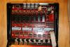
I built a Paia +/-12VDC power supply kit and an AOUT_NG to hook up to my MB-6582 and needed an enclosure. (I have a bird sharing the room and she has great fun chewing through wires on electronics projects...) I recalled I had a small plastic box from some Rocher chocolates in it at one point, so I decided to make it into a case. The two PCBs just barely fit, so with a little milling and drilling I made up a nice little case. First pic is the original box + the 2 PCBs. I drilled holes in the bottom and used leftover standoffs from my MB-6582 project to mount them. Second pic is the box set up to mill ventilation slits like I did for my MB-6582 case. Making vent slits is a breeze with a small milling machine and a 1/8" end mill. Third pic is the base of the box with its vent slits all cut. Fourth pic is me setting up to drill holes for all the 1/4" jacks and the wall-wart connector. [EDIT: Please ignore the completely unsafe mounting of the milling machine onto cement blocks (don't try this at home!). At least I have my safety glasses!] IMG_4352-AOUT_NG plasic box + boards.JPG IMG_4354-AOUT_NG milling vent slits.JPG IMG_4356-AOUT_NG slits milled.JPG IMG_4378-AOUT_NG drilling holes.JPG IMG_4352-AOUT_NG plasic box + boards.JPG IMG_4354-AOUT_NG milling vent slits.JPG IMG_4356-AOUT_NG slits milled.JPG IMG_4378-AOUT_NG drilling holes.JPG
-
If you're trying to de-solder the chips (more) safely you might consider Chip Quik (http://www.curiousinventor.com/store/product/102). Pretty amazing stuff and makes de-soldering stuff easy. They have a video of it.
-
Need Help - No Sound and strange Interconnection Test results
fussylizard replied to ben-o-matic's topic in MIDIbox SID
The first thing to keep in mind is that you should have run the interconnect test and/or testtone app *before* trying it with the SID chip. That way in the event of a problem like you are having here you won't damage your SID chip. Hopefully it escaped just fine. <end lecture> :-) Anyway...Did you test the pins of the 74HC595 chips to ensure they are getting correct voltages (google for the datasheet)? (This also should be done before inserting chips to prevent damaging them.) If that works out okay, then (as noted in the readme.txt file that comes with the interconnect app) you should be able to move the modwheel on a MIDI controller to select different pins. Basically everything should be 0V except for CS# which should be +5V when not selected via the modwheel, and +5V when selected (except for CS# which will go to 0V when selected). Do the other pins toggle between +5V/0V as expected when they are selected? If other pins are working then check for shorts on the bad pins (they might be shorted to +5V somehow). If other pins are not changing when selected via the modwheel, again check the soldering for shorts. You also may have a problem with the interconnect between the boards, so double-check your wiring. I'm not familiar with the standalone config of CORE + SID (I built a MB-6582) but you apparently need a 1k resistor and a diode for the CAN bus even if you have no slaves, so make sure you have that diode and resistor as shown in the diagram posted by zgba. Good luck! -
The LCD backlight is only powered for CORE0, and without a backlight it can be very difficult to see any text from the LCD. How much you can see probably depends on your backlight. At first I thought there was a problem with my CrystalFontz LCD on CORE1 but then I realized it was just the backlight wasn't powered and I could *barely* see the text with the contrast set just right. The easiest way to test for a dead/partially-dead PIC is to test CORE0 with a good PIC, then move the suspect PIC to CORE0. That way your backlight works and you know everything else is working so you can isolate any problems to the suspect PIC. One final thought-don't forget to set J11 to connect CORE1 to the MIDI Out port when testing MIDI to CORE1.
-
Yeah, Wilba's stuff always looks perfect. The innards of mine looks like it was put together by an inebriated chimpanzee... I used standard ribbon cable from SmashTV to attach mine (the older gray stuff he used to sell, now he only sells the pretty multicolored stuff) using a right angle header on the base board (Mouser 517-5111TG) and female crimp sockets from SmashTV. I soldered the other ends of the wires to the control surface. I opened and closed the case a ton and never has issues with broken wires. I couldn't quickly find the .100" wire that Wilba used on Mouser, so I just used the ribbon cable I had sitting around.
-
I've seen the same thing on mine (can't recall if it was that *exact* same screen and those exact same characters but I'm pretty sure it was). So that would suggest it is either an LCD bug or a software issue. I'm guessing LCD bug since as many bassline demos as TK has done he would surely have noticed and fixed it if it was a software issue. :-) I have a Crystalfontz display CFAH2004A-YTI-JT.
-
Woohoo! Glad to hear you're sorted out then! After all the help I got building mine, I'm glad I could pass along some love. :-) I'm still sorting through all my pics and what-not from my build so I can post a summary, parts lists, etc. Looking forward to more pics from you.
-
@futureman - btw did you make your own knobs for that panel, or did you buy them? I particularly like the knurled one in the bottom center of the panel. I have some alps knobs coming from the bulk order, but I was thinking about trying to make some similar to the knurled one you have.
-
@futureman, @mule - I've always shied away from square holes since I thought a DIY approach would look, well, DIY. But your two projects prove otherwise! Thanks for the inspiration! Today I made a simple enclosure (for an AOUT_NG and a Paia +/-12VDC power supply for it) out of an old plastic box that some chocolates came in (Rochers). It was fairly thin plastic so it cracked a bit with all the drilling but it's good enough for now. I made a horrible looking hole for a 9 pin d-sub but the connector covers it. I probably should have tried the "file to size" method instead of winging it on the mini mill. I'll post some pics later this week.
-
My 6582s (from Wilba) were getting hot enough to where I couldn't keep my finger on them. I don't know if I would have gotten burned but it was hot enough I didn't want to find out. I also have a fan and cut vent slits which will help. I thought about trying to use heat sinks for CPUs or something and gluing them, but when I found these I figured I'd give them a shot and they worked great.
-
Silly question, but have you tried adjusting P2_CORE1 (contrast for the LCD)? You can also fiddle with P1 to adjust the backlight level. Both of these are the pots located on the base board in the lower right quadrant near J11 (where you select the core for MIDI Out). Other than that just verify your LCD is wired properly (getting the backlight is a good start).
-
LOL, I completely understand. It took me a bit to get my head around it when I was looking at it on the Aavid site. There is also a little lip on the part of the heatsink that sits on the top edge of the chip (barely visible at the top right edge of the chip in the picture) to prevent the heat sink from sliding off on its own. So no screws or difficult to install clips at all. Pretty clever.
-
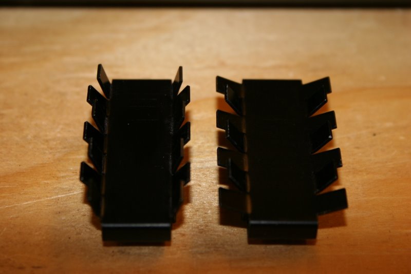
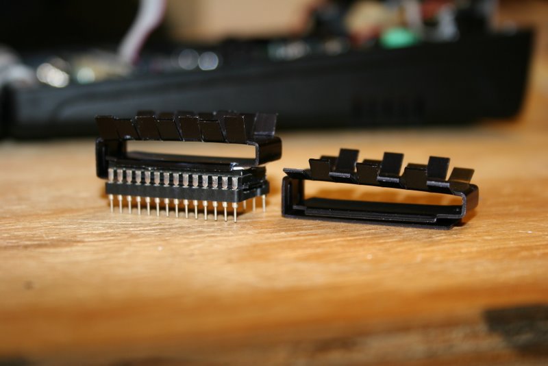
In case others are interested, I found some heatsinks for 28-pin DIPs that work perfectly on SIDs. They are Aavid Thermalloy part #580600B00000G (http://www.aavidthermalloy.com/cgi-bin/stdisp.pl?Pnum=580600b00000g#). They are nonstock at Mouser and Digikey but I did find them in stock at http://www.electronicprecepts.com/. It is US-based and I have no idea if they ship internationally, but I called them, payed for them by credit card, and they arrived a few days later. IIRC they were about $1.50 plus shipping. I got thermal paste at a local computer shop since Electronic Precepts only sells it by the bucketfull. One thing to point out is that on the MB-6582 the SIDs are so close together that the fins of the heat sinks touch. I ended up bending the fins up a little with pliers to prevent this. The metal or maybe the coating on it made a little cracking noise for each fin I bent, but it seems fine. I'm not sure what affect this has on the heat dissipation but at any rate I feel a lot better knowing my SIDs have heat sinks since they 6582s were getting pretty hot and they only use 9V. 6581s probably would be worse given the 12V supply they need. If you are using a standalone SID module I would imagine these heatsinks would fit fine but I don't have a SID module so I can't guarantee it won't hit other components. You could always stack IC sockets or bend fins to gain clearance if that is a problem. The first pic shows the unbent heatsink on the right, and the bent one on the left. I only had to bend every-other fin. You can see the white-ish crack lines at the base of each fin I bent. The second pic shows the heatsink attached to a SID. The heatsinks use an interesting clip-like system to attach. From top to bottom on the left I have the top of the heat sink, some thermal paste, the SID, the bottom of the heatsink, and an IC socket. The bottom part of the heatsink slipped between the bottom of the SID and the top of the socket perfectly. I used two IC sockets per SID per Wilba's advice (one soldered to the PCB, one attached to the SID and left there as shown here). I had to pry the SID up slightly from the socket to allow the heatsink to slip in. I just put a thin coat of thermal paste on top of each SID (don't overdo it!) and slid the heatsink on while holding it open (to prevent it from scraping off all the thermal paste). The third pic shows all 8 heatsinks installed on the MB-6582 base board. It's a tight fit even after bending the fins, but it all fits after bending the fins.
-
That cutout is *very* impressive, it didn't even occur to me it was handcut until Imp asked about it. Can you post more details on exactly what steps you took? Might come in handy someday. It sounds like you used a drill to cut enough holes to get a jigsaw blade in to do the rough cut, then filed it down. I've never tried that, but if that's what you did I'd never have guessed you could get such a nice final result.
-
As promised, here's some pics of the Paia kit. First pic is what comes in the kit. I was a bit surprised that the kit used a 12VAC wallwart transformer. I was expecting a 15VAC wallwart to make up for the voltage drop over the 7812/7912 regulators, but I emailed Paia support and they told me the circuit used a voltage doubler to prevent the voltage drop (so that's why it has so many large caps!). Second pic is the assembled power supply kit connected to an AOUT_NG. I had initially tried testing the AOUT_NG with a PC power supply but I was going crazy with all the wires running everywhere. It sure was nice just to hook up a small ribbon cable and be up and running. Calibration was straightforward once I realized my multimeter probes had GND and CV swapped (duh!). Third pic shows my MB-6582 connected to a Moogerfooger lowpass filter. The MB-6582 has an LFO modulating the filter cutoff via the AOUT_NG. I haven't done anything worth recording yet, but when I have something interesting I'll post it. I'm not sure how clean the output of the power supply is. It is designed to power a Paia modular synth, but it works fine. So far I can recommend it as a simple option for powering an AOUT_NG. It's $42 + shipping. You might find cheaper, but it seems to work well and no parts scrounging on Mouser or Digikey required. Now to sort out a case to hold these boards... I'm also thinking about trying to combine this with a MIDIBox CV. The basic idea would be if the MB-6582 is powered up and plugged in, the AOUT_NG would ignore the MIDIBox CV core. I probably just need to multiplex the signals going to J1 on the AOUT_NG and select between the MB-6582 and a MIDIBox CV core. I can detect the +5V coming from the MB-6582 to select the appropriate source for J1. Should be straightforward, right? I guess the first step is finding some sort of multiplexer that can pass analog signals. If anyone has any recommendations that would be great (maybe the Maxim 4702 4xSPDT analog switch assuming it is available in a hand-solderable package?). IMG_4347-paia 9700R12 power supply kit parts.JPG IMG_4350-AOUT_NG with power supply complete.JPG IMG_4351-testing AOUT_NG with MF-101.JPG IMG_4347-paia 9700R12 power supply kit parts.JPG IMG_4350-AOUT_NG with power supply complete.JPG IMG_4351-testing AOUT_NG with MF-101.JPG
-
Speaking of power supplies, last night I built the +/- 12V power supply kit from Paia. After all the MB-6582 soldering (with all the parts so close together and small pads) it was a breeze, with miles between parts and pads. I'll post a pic later (POIDH). I've not tested the supply or tried to power the AOUG_NG yet but I'll report on it later. OT sidenote: I've been having some good fun with an Arduino board and some serial tri-color LED modules this week. Is it just me or does Arduino and the related items feel like building Legos? You just connect all the boards together with jumper wires, paste the supplied sample code into the Arduino IDE, and <viola!> you have a working microcontroller app. Fun stuff. (I'm about to interface it to an accelerometer that is not "plug and play" so it's time to turn my brain back on. :-)
-
Wow, nice job! It looks great. I'm continually blown away by how good it sounds and its flexibility.
-
I did the pots on mine a month or two ago. I compared 500k audio taper and 100k linear taper. I preferred the linear taper since they had a more useful range, but YMMV of course. :-)
-
They worked out pretty well. I had to bend the fins up a bit since the SIDs are all so close together, but other than that they fit perfectly. I've been busy w/ other stuff so I've not yet posted pics about it. Maybe I'll have time tonight before my wife and I go to the midnight show for the new Harry Potter movie. :-) BTW I ordered a +/-12V power supply kit from Paia (turns out they are in Austin, I wonder if they have a storefront or something) for the AOUT_NG module to be controlled by my MB-6582. Should be here today. I figured the $40 or so was worth it to avoid crawling through the Mouser site hunting down all the parts to do it myself. How's your MB-6582 coming along?
-
Be sure to use tons of JB-Weld to avoid having problems like I did with spacers coming loose on the back of my FPE panel. I'd probably just use a little initially, then reinforce it after the initial coat dries. If your blobs of JB-Weld are too big in the corners you can cut off the corners of the top case like I did (see pics earlier in the thread). Good luck!
-
Cutting fluid *might* also help, but with the thin metal for a front plate it probably won't matter. FWIW WD-40 works great as cutting fluid on aluminum. Also, if you clamp the piece you're drilling onto another piece of aluminum so you can "drill through" the front plate into the bottom piece you should get a cleaner bottom edge on the front plate.
-
I believe I've seen LCD bezels that might work *if* you're mounting the LCD where the LCD protrudes through the hole. You could make a rough-ish cut, then fit the bezel around. Or even make a bezel yourself out of wood or plastic with a hobby saw and small miter box (X-Acto makes one). For the MB-6582 PCB, the LCD is mounted a few mm below the front panel so things are not so easy. Using a jigsaw with a fence of some sort is probably best, or even a small hack saw and a bit of filing. You can also try nippers (http://www.curiousinventor.com/store/product/91 or similar). There's also some DIY metalworking videos at http://www.curiousinventor.com/guides that I just noticed. I've not watched them yet (not during work!) but there may be some interesting info. If you have a drill press you could try buying a cheap end mill and build a fence of some sort to guide the workpiece along and try to cut it that way. And end mill looks like a drill bit but cuts from the side. You might be able to use a router of some sort to do something similar. (If you have a Dremel tool they have a router attachment that might work.) If you decide to go the end mill route PM me if you need help picking an end mill since there are about a zillion variations. I have a small milling machine so I'm somewhat familiar with them. One final idea would be to get a piece of rigid plastic that forms an L shape (say 1mm x 3mm) and sort of make your own bezel that glues to the front panel. If you put a nice 45 degree cut on each corner it might look rather nice and cover up any rough cuts. Good luck!
-
Thanks! I hadn't quite gotten around to archiving that to PDF myself.
-
Do you only get the hum after you play a note, or is it always there? The 6581 I initially tried never seemed to get the release volume all the way to zero. I'm now using 6582s and they are much lower noise. If you can test w/ different rev of SID that might be interesting (easier said then done of course). Took a quick peek at the signal and it appears to be peaking at around 100 hz, not the usual 50 or 60 hz ground loop hum. The waveform sort of reminds me of the TB-30, so if you can figure out how to change the pitch maybe it will be a highly-sought-after modification. Don't forget to run it through a distortion pedal! :-) hum.PNG hum2.PNG hum.PNG hum2.PNG
-
Hmmm. For whatever reason those last few blocks are very slow. 1000 ms may not be enough, but try it. 2000 ms should be plenty based on my experience bit YMMV.