

jjonas
-
Posts
422 -
Joined
-
Last visited
-
Days Won
24
Content Type
Profiles
Forums
Blogs
Gallery
Everything posted by jjonas
-
The setup idea was the third one on your list, i.e. controller -> MIDIO128 -> various midi equipment, no computers involved. It was for an guitar FX / midi case I've built for easy portability and band rehearsal purposes (and why not for use in the studio as well :-). Our keyboardist already has two full-sized keyboards on the stand, and adding a third one (with an extra stand) felt unnecessary, had the USB option been available in the form I originally thought. From what you write it sounds like a USB-powered minicontroller won't work the way I thought it might, so maybe we have to go for a clunkier controller for the vocoder, Blofeld & Midibox sample player (under the guitar pedals) after all. Thanks for all replies!
-
The answer is I don't know, because at present I don't have a USB-powered keyboard controller. I'm thinking of getting one, but only if I can be fairly sure it can be made to work with MIDIO128, which is an integral part of my midi setup. I'm not so familiar with USB things, so as it looked a bit hairy, I had to ask about it here. A small controller with a regular midi out would be better as far as I'm concerned (at least I know it would work with my setup), but the USB ones are more readily available second hand.
-
Hi, does the USB jack on the MIDIO128 also send 5VDC if it's powered with a "normal" PSU, or is the jack meant for just receiving USB power? I'm asking because I'd like to know whether there's any chance of connecting one of those small 25 key midi controllers that take only USB power. A further issue: if I've understood correctly, a cable with a mini-USB-A on the one (controller) end and a standard-B on the other (MIDIO128) doesn't match official specifications (wikipedia). Is this something that can be circumvented with adapters? Even if it is possible in principle, are there reasons why it isn't a good idea in practice?
-
Hi, I have an MB6582 with 4x8580 and 4x6581, and I got myself a stereo noise gate by building two MXR guitar pedal noise gate clones following the schematics on tagboardeffects (I built the stock version with the three changes mentioned in the very beginning) and boxing them up with a dual pot. (UPDATE: If you build this, I advise to use 2N5485 instead of 2N5952 as transistor Q3, as it gives clearly better results. I built a second stereo unit of these today (24.7.2014), and went with the "stock version" schematic (see link above), using a 2N5952 as specified there and believing that that was what I had built before. However my earlier unit was gating the noise much more effectively, and after a while I noticed I had built it with a 2N5485, although it was otherwise like the "unmodded stock version" [bTW at some point I built the modded mono version as well and tried it on guitar, IMO the extra controls didn't really do that much]. Changing to 2N5485 fixed the problem. I don't know why this is though. Here are the datasheets, in case someone feels like researching.. 2N5952 and 2N5485.) (UPDATE 2. March 5th, 2018. I had one more PCB for this lying around it, so I built it today and it worked without any problems. One thing I noticed was that in my screenshot below capacitors C5 and C13 are 100nF, but in the original tagboardeffects layout they're 10nF. However, I've built all mine, including the one today, with 100nF caps and haven't noticed any problems.) The two switches can be used 1) to switch between battery and adapter power (= off for battery power), and 2) to switch off the stereo input jacks' rings to use it in mono (for guitar etc). I'm not sure, but is the second switch actually redundant, as connecting a mono plug into the stereo jacks just connects the rings to ground? I put it there as a precautionary measure to avoid buzz and other problems, but then thought maybe it isn't necessary. Anyway, here's a YouTube video on how it works on a pair of 6581s: http://youtu.be/BKBQBRA9Obw
-
Go to www.ucapps.de and check the panel on the left (scroll down), there's a Midibox SID v2 Synth section with a link to the User Manual. Start with the First steps section and go on from there. I have used Rutger's Java-based editor, apparently it's not maintained anymore, but for me it works. There seems to be a newer editor available, but I haven't tried it (or them, if there's several). Check this link and under heading 'Alternative Editors': http://www.ucapps.de/midibox_sid_manual_ed.html This one I cannot answer. Go to ucapps.de and check the panel on the left. At the top there's a section called MIOS, click 'MIOS8 Download'. There, among other things, you will find the newest MBSID firmware (at present v2_043).
-
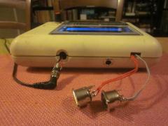
 Hi, I had already built a and a with Mellotron samples to serve as a "digital Mellotron", but now I decided to scrap both these stand-alone units and build them both inside a midi controller keyboard instead for more convenient use – no cables or other hassle. Plus you can still use the keyboard to control external stuff as well. Here's what the finished unit looks like: The sample player has no hands-on interface, there's just 8 banks of mellotron samples available on channel 11. The MBSID however comes with the LCD plus the necessary buttons. The four red knobs don't do anything yet, but I'll assign them to filter and LFO tweaking functions later. Note that the knobs are aligned better than the buttons – that's because the front panel had holes for knobs underneath the "M-AUDIO" panel, probably because the same case is used for some more advanced model with knobs as well. Below the keyboard from the inside. On the left there's the original PCBs of the keyboard, and on the right there's what I put in. The placement of the sample player (SP) stuff. I use the keyboard's own 12VDC switching PSU (2A) to power the whole thing (i.e. keyboard, MBSID, SP), and I think a slightly bigger cooling element for the 5VDC regulator wouldn't hurt here. While testing this part of the keyboard I had problems with the sample playback quality worsening in 3-4 minutes and eventually turning into some kind of square wave sound. I managed to correct this by changing to another SD card interface. I haven't done further troubleshooting yet to find out whether it was the microSD or the adapter that caused the problem. In terms of height, there was barely enough room for the partly populated LPC17 PCB and the MBsid PCBs, but they did fit. Originally I built the SP inside a Roland PC-180A, which was ok too (though I had to cut out some plastic), but when I got the idea to build the MBSID inside a keyboard as well, I had to do it using another keyboard, because the Roland didn't have space for an LCD. The placement of the MBSID stuff. Probably I could have used the "normal" SID modules as well, but I preferred to use the one I reorganised and etched myself because the connectors fit better. As you can see the "SIDs" are actually two SwinSID nanos. Because the realistic alternative would have been to use two 6581s, I decided to keep the the SwinSIDs to spare myself from having to go buy a 15VDC PSU and from using further heat sinks. The SwinSID sound is not as good, but it's definetely ok, and even more so as I built this for band rehearsal purposes – of course recording will be performed on an MB6582 with the real stuff in it :-) Here's how I initially tried to put the tactile switch buttons in. There was *very* little space above the keys here in the cover panel, and it turned out that using hot-glued 5mm hex nuts and a strip of veroboard with tactile swtiches on it didn't work for that reason – it was too much to fit in. So I got rid of the hexes and the veroboard, and hot-glued the tactile switches directly on to the panel: Even that fit only barely, but it did fit! On the previous picture you can see on the right that the four buttons (up-down-menu-shift) are still on a PCB that's been hot-glued on. However I had to change that too and just hot-glue the buttons directly on, otherwise there was a key that got stuck. The two narrow strips of veroboard on the right are for MIDI (left) and power supply (right). I soldered wires to the the legs of the keyboard's midi out connector, and the midi messages are distributed to the MBSID and SP from the veroboard. Likewise with the power supply, though in this case I added a separate power switch for the MBSID/SP, in case you need just the keyboard on to play "external" modules or whatever. Finally, the unit from behind. Three new items: SP out (mono), MBSID out (stereo), switch for MBSID/SP. NEAT, INNIT?!?!?!?! :-)
 -
Hi, lately me and my band have been using MIDIO128 at our band rehearsals to play a few synthesizers (including my datassette MBSID), and it works great! Based on some experience I have a small (I think) feature request. Currently when you stop a file playing before it's finished, for example if the start of the song fails, the singer forgets the lyrics mid-song or something, and it's just more satisfying to start from the beginning and try to get the whole thing right, you have to press a button three times: first stop, and then when you push the "<" button, it takes you to the beginning of the previous song, from which you then have to come back to the song you stopped with a press of the ">" button . Now the song you stopped is at its beginning and you can hit play again. In my opinion – or for my purposes anyway – it would be handier (after the initial press of the stop button) to have the first press of the "<" button to take the stopped song to the beginning of the song that was stopped, instead of the beginning of the previous song. That way one button press could be eliminated, and in my opinion the whole thing would be a bit more intuitive. But perhaps it's a matter of taste, and others might object to this. What do people think?
-
Thanks to both – success!
-
Hi, I'd be interested in having an extra midi out on the MIDIO128, but I'm not sure how to understand the LPC17 core page instructions to bring this about. However if I'm not mistaken it's not necessary to build an IIC MIDI module. Regarding port J4B the page says: "MIDI OUT4 will be available on the J5B.SA pin, it isn't required to remove R11 if already soldered - it doesn't hurt." However, I don't see a pin with that name on J5B; only the bottom row has names printed on them, and they are A7, A6, A5, A5, 3.3Vd. Regarding port J5A/B the page says: "And J5B.A6 (MIDI IN3) and J5B.A7 (MIDI OUT3) provide an alternative MIDI IO port as well if "#define MIOS32_UART_NUM 3" has been added to the mios32_config.h file (defines the number of UART ports). So if I add "#define MIOS32_UART_NUM 3" to the config file and then compile & upload, my MIDI OUT 3 pin is at A7..? And that is to be connected to midi out socket's pin 5, pin 4 to 5VDC (from e.g. J4A, is there a need for an extra resistor?) and pin 2 to ground..? (http://www.midi.org/techspecs/electrispec.php)
-
Here's a video I made, I'm using a MIDIO128 to control the MBSID to play a simple tune. I have also ditched the old double SID module I had as there was some problem with the second half, and used Fritzing to redesign a new double SID module to save space; I ditched the rectifier and regulator bundle, as SwinSID can be run off the core's 5VDC regulator. Also the audio in had to go.
-
Talking of noise gates, anyone here ever build this: http://tonepad.com/project.asp?id=18 I'm still waiting for the FETs to arrive, but it would be nice to know someone here managed to do it (= for advice), because based on the build reports the schematics / parts list seem not be completely in order.
-
Hi, I was wondering which components on the SID module schematic might be redundant if you're building the module with SwinSID nano instead of 6581/8580. If I understand correctly, at least the 9/12VDC supply bundle is redundant, because SwinSID solely from 5VDC at J2. What about filter caps C1 and C2? And if you know you're not going to use audio in, I guess you can leave out everything connected to SID pin 26 and connect it directly to ground? Is this all?
-
I tried two swinsids (nanosid) in a 3-core MBSID with a pair of 6581s and a pair of 8580s, but I found the swinsid sound level too low in comparison to the original SIDs.
-
 That's one idea worth considering -- maybe I'm just too hung up on finding a mechanical (i.e. "real" :-) solution, where a moderate dose of hot-glue would simply do :-)
 -
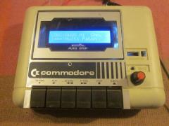
Hi, I thought I'd drop a few lines on an MBSID build into a C64 datasette using one nanosid (i.e. swinSID). I had leftover parts from my "main" MBSID build; I had originally planned to build four cores, but I couldn't fit them all into the C64 case that I used. So I had all the parts lying around except for an LCD, which I now decided to get, and put the parts to good use. I had two SID module boards from Mike, but in order to save space I decided to etch my own "double SID PCB" (and a DIN2 board as well) using the laser printer + clothes iron method. This was my first etching project and maybe the quality could have been better, as I couldn't get the other half of the double board working. So in the end I just made it with one sound chip, I hope I have time and energy in the future to redraw a complete core + 2 sids PCB with Fritzing or something for an optimal fit.. and anyway it's good that all projects are not finished immediately :-) At the moment the datasette insides are a mess, as I guess with most of these modular builds. But it works. I decided to use nanosid instead of the real thing because that made voltage supply much easier – you just need one regulated 5VDC for both the core and nanosid. Plus it's less noisy than a 6581. I kept all of the the datasette's buttons to have them push the actual MB buttons 1-5 + menu. The core PCB regulator (follow the red-white-black wires) is attached to the button plate for heat sink purposes. The two buttons on the right that are hanging loose (Up & Down) will to into the counter hole once I get my hands on a hot glue gun... the LCD is attached to two screws that I hot-glued onto the datasette cover.
-
From the album: jjonas - midibox SID
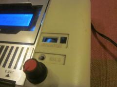
The save light hole has been used to house the Shift button (which is hot-glued in place). The Up/Down buttons will be in the counter hole. There's still a place for one more button in the counter reset hole :-) -
From the album: jjonas - midibox SID
Connections are still a bit unfinished. The 9VAC socket will be a nice fit, just like the mono jack already is, but perhaps the midi IN and OUT have to remain more or less like this. Unless I find the energy to carve holes for them and bend the connectors to fit the datassette's shape.. -
From the album: jjonas - midibox SID
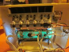
Here's how I used the datassette buttons to operate the actual buttons. I cut out most of the supporting metal structure of the buttons inside the case and installed a self-made metal support for the actual buttons. The white-black-red wire bundle on the right connects the 5V regulator (visible in the pic) to the core PCB; the regulator is connected to the buttons' metal support in order to use it as a heat sink. -
From the album: jjonas - midibox SID
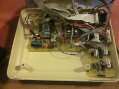
Apart from the core PCB I etched the boards (2x SID + DIN2) myself with the laser printer & clothes iron method. Bankstick was built on veroboard. I couldn't get the other sid module working, I'm not sure whether it's the parts or the board, the etch quality was not the best. I decided to go with just one chip for now and leave the second chip as an option for the future. The empty space in the front is reserved for the buttons. -
From the album: jjonas - midibox SID
Midibox SID v2 with one sound chip built into a datassette case. All the original buttons are functional: Rec, Play, Rew, FFwd = MB buttons 1-5, Eject = menu. -
This seller is highly recommended! Excellent communication & fast shipping!
-
I'm selling a populated and functioning MBSEQV4L control surface PCB. So it's working, it just wasn't what I needed. The price for the board is $15 at SmashTV, so I'm selling it for 15€, which includes postage within the EU. Payment by Paypal. PM me if you're interested.
-
The latest pre-version I've been using/testing is pre4, and button-wise it's completely sufficient for me. So, as far as I'm concerned, there's no need for extra buttons. I'm thankful for all the new features this far and just looking forward (fast forward :-) to the transpose function :-)
-
I updated to bootloader 1.009 last night and then uploaded pre4 (all via USB), and for me it went fine (I was using MIOS studio 2.3.0. on Wine on Ubuntu). I tested the FF/Rew function and song position after pausing, and they work for me now. Also you can now see the song position when you're FFing/rewinding. Super! :-) As a separate matter, just bouncing off kpete's comment, not necessarily responding to him: I have two USB-midi cables, one of them is a Cakewalk one, and I've have problems with it, whether "advanced" switch is on or not - not only with LPC17 core but also the PIC based core (with MBSIDv2). What did work (and what I've been using since) was a few euro cheapo cable that I bought later on eBay. That has been my answer to USB-midi communication with midiboxes ever since :-)
-
I couldn't find how to attach files to PMs, there was no attachments section in the (full) editor like the one you have when you write to public forums, so I attached it here.. hintikka.mid.zip
