All Activity
- Past hour
-
After some digging/debugging, it turns out we need to set the following variable to '1' to have this 5th LED working: DEFAULT_MB6582_CS I found this out by this table in src/cs_menu_leds.inc where the fifth bit (reading from right to left) is only set in the first 'if' routine: CS_MENU_LED_LFO_Wav_Pattern andlw 0x0f ; 16 entries JUMPTABLE_2BYTES_UNSECURE retlw b'00000001' ; Sine retlw b'00000010' ; Triangle retlw b'00000100' ; Saw retlw b'00001000' ; Pulse retlw b'00010000' ; Random #if DEFAULT_MB6582_CS retlw b'00100001' ; Positive Sine retlw b'00100010' ; Positive Triangle retlw b'00100100' ; Positive Saw retlw b'00101000' ; Positive Pulse #else retlw b'00010001' ; Positive Sine retlw b'00010010' ; Positive Triangle retlw b'00010100' ; Positive Saw retlw b'00011000' ; Positive Pulse #endif retlw b'00011111' ; reserved retlw b'00011111' ; reserved retlw b'00011111' ; reserved retlw b'00011111' ; reserved retlw b'00011111' ; reserved retlw b'00011111' ; reserved retlw b'00011111' ; reserved
- Today
-
I have still exactly the same 'issue'... From another place in the manual ( LFO section ) http://ucapps.de/midibox_sid_manual_l.html Wav (Waveform): selects the shape of the LFO. Following waveforms are provided: Sine, Triangle, Pulse, Ramp (Sawtooth), Random (Sample&Hold), and positive Sine/Triangle/Pulse/Ramp So I would indeed expect the 'positive' LED to be lit (new style?), in stead of the multiple leds (old style?) when selecting the other waveforms in the active/selected LFO... Will be doing some more investigations in the ASM configuration file, as it seems to be another setting :-)
-
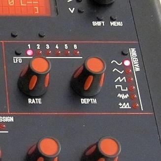
I looked at exactly the same thing and thought the same thing. But since the firmware is relatively old and I couldn't find anyone else whose LED wasn't lighting up during my search, I thought it couldn't be the firmware. That's what I'm thinking too, but where do you turn this feature on? For me, for example, Sine+Random light up at the same time when I have a positive Sine LFO waveform. That's how it's explained in the manual. You should be able to turn off this display feature and turn on the separate LFO positive LED, right? It is installed in many MB 6582 models. (Picture attached) But when I compare the ASM files, I can't find any differences. And in this video, you can see at the beginning how the preset is changed and then LFO 1 has a positive triangle waveform. So there, the LFO positive LED lights up instead of the random LED. https://www.youtube.com/watch?v=FA0i5-bAfUQ
- Yesterday
-
From what I gather from the manual and changelog, this LED indicates whether you have selected a „positive values only“ waveform for the LFO (instead of applying the default workaround by showing waveform LED + Random LED). It does not indicate that the value of the LFO is currently positive.
-

Is there a clock signal for a LED in the MBHP core
acfnews replied to acfnews's topic in MIDIbox SID
Hi @TK. A great alternative for this would be to have the active SID led 'flash/dim' whenever there is midi activity like this is done in the FM v1. (instrument 1/4 led flash/dim) Would that be a feasible option (both programming wise, as resource PIC wise)? -
my problem was a bad driver chip on the bhp_seq interface board....
-
Hi Keeze, I am not sure how, but I missed your offer. Many, many thanks, but sorry again for missing your response. Currently I am running with 2 blue modules, and my problem was solved by replacing the driver IC on the mbhp_seq interface board. So many thanks for your offer, and unless your are going to scrap our lcd's, I am not in a need anymore.
-
I just shared this thread in the Discord channel. Maybe that helps. At least there are knowledgable people there :-) Also tried to find some clues in the code, but this is hard for me. I did find something interesting (not sure if it is relatated at all), in src/cs_menu_leds.inc Searching for the word 'TMP5' shows in line 127: 127 ;; TMP5[5..0]: LFO waveform and in line 159: 159 ;; TMP5[6]: SID play state So in this file it looks like it's structured, but is the 'array' [5..0] correct? Should it be [4..0], and should there be a separate section for TMP5[5]?
-
Hello acfnews, Thank you for your reply and your test. I suspect that the LED would indicate the positive range of the currently selected LFO. That would make the most sense to me. In some pictures and videos, I find SIDs that have this LED installed. But I have not seen it light up in any picture or video. Perhaps someone who has installed this LED and has it displaying something can say more about it. If you find out more or get the function to work, please let me know. :-) Best regards, Oli
-
Hi Oli, I just stumbled upon your question, and I never considered this function, however, it might be interesting... My first question would also be, which of the LFO's would it indicate, as there are 6? Is it a sum? Not sure.... As a test I configured my ASM file, and added a line for the function (and removing a working function from the hardware position just like you did). In my case the first SR1,0 (normally used for SID1 LED indicator). DOUT_ENTRY TMP5, 4, 0, 0 ; LFO Random LED DOUT_ENTRY TMP5, 5, 1, 0 ; LFO positive LED ;; additional LED functions which could be added: However, on first test, no magic....` I will also have a look to see if I get thus going in a way...
- Earlier
-
Many thanks for the quick reply. Yes, I sent another function to this LED as a test and it then worked without any problems. So I can actually rule out everything on the hardware side. Unfortunately, I can't find many SIDs where the LED is used. I also couldn't find any videos on YouTube where someone has installed this LED and you can see it in use. In my *.asm file, the DOUT line looks like this (Shift Register 6): DOUT_ENTRY TMP5, 5, 6, 7 ; LFO Positive LED Is that all I need to enter for the LED function to work?
-
Have you used the diode test function with your multimeter to see if the LED illuminates? First thing I would check is if the anode and cathode are in the correct holes or if the LED is dead.
-
Hi, I'm currently building a MIDIbox SID V2 with the complete Control Surface. Everything works great, except for one thing. The additional ‘LFO POSITIVE LED’ never lights up. I can rule out errors on the hardware side, as I have already assigned ‘TMP5, 5,’ to other DOUTs and the LED does not light up then either. However, other functions are displayed on the outputs without any problems. I have of course already changed the LFO DEPTH and RATE. With positive LFO waveforms, for example, Random + Sine lights up, as described in the manual. Can anyone tell me what the problem might be or does something else need to be changed in the code? Thanks!
-
Absolutely beautiful build and much more affordable front panel design also. If you could upload the STLs to the MB-6582 wiki page under the "Panel Designs" section it would be the best place for them: http://www.midibox.org/dokuwiki/doku.php?id=wilba_mb_6582 Otherwise they will not be preserved for future builders.
-

[S] 7x MB-LRE8x2 CS Rev 2.5 (fully stuffed with parts)
Phatline replied to Phatline's topic in Fleamarket
the rest off them are now sold to @wlinart can be closed - thx. -
DM sent
-
First of all sorry I am replying to an old topic. I hope there's still someone reading this topic and able to help me. Many, many years ago I built an MB-6582 with 8 real 6582A chips in it. I use an original C64C powersupply. I love my MB-6582 but it's a bit to noisy for my taste. So I'm considering buying 4 ARM2SID's to replace my 8 real sids. I think that would make it a lot quiter. If I understand correctly the arm2sid only requires 5 volts. I am not very skilled in electronics (when I built it, I simply followed the steps). I suppose I can still use my current C64C power supply, but I also read they can destroy sids (or more) when they fail, which is not very unlikely after more than 40 years. So with the new arm2sids I think I also want to replace my power supply for a modern one. Can I simply buy myself a 5V power supply and attach that to the 5V pin (number 5) of the power connector and also connect the ground pins? Or do I have to remove components from the board. The benefit of not having to remove components is that I always can decide to put back the original and use my original power supply. So what would be the simplest way to use a new 5V power supply with my arm2sids without having to remove a lot of components from the pcb? Are there schematics of the MB-6582 somewhere on the net so I (or a skilled friend) can look at the my whishes with the power supply? Also I considder recreating the control surface, because I'm not happy with the way I constructed it many year ago (the leds are not equally leveled). I think it's hard to remove all the leds. Can I still get the control surface pcb somewhere?
-

Red and black sammichSID replica w/ 2xSID emulators
sqwilliam replied to Sgw32's topic in Fleamarket
I have DM'ed for a PCB Thanks -
I am trying these as they are similar but a little smaller - will update if they work… https://uk.rs-online.com/web/p/memory-card-connectors/7636794 EDIT: It works fine - but footprint is a bit smaller so may need gluing as well if the card is going to be removed often.
-
Does anyone have spare sd card holders for the core or a suggester part substitution? (It is actually for a different pcb but is the same part as used on the stm32f4 core) 3M have stopped manufacturing them and I havent found an alternative that is the same size as SD-RSMT-2-MQ or SD-RSMT-2-MQ-WF ( I have found 9/11 pin versions which are shorter with different positions for the mounting tabs). Thanks a lot.
-

Put Waveblaster daughter board (Yamaha DB50XG) in a box?
freddy replied to SeverityOne's topic in Design Concepts
Thanks a bunch, stever! Looking forward to try it later this week when I return home. f -

Put Waveblaster daughter board (Yamaha DB50XG) in a box?
stever replied to SeverityOne's topic in Design Concepts
Prompted by a message from freddy, I've attached the project files below. They contain the source and the binaries for the bootloader and the main code. 1.05 is the latest version - there was a fix in the bootloader and the main code. I included some memory in the final hardware design but never got around to doing anything useful with it. I had plans to save one or more demo tunes as MIDI files and perhaps save some settings as profiles for different scenarios - my interests had moved on before that happened. You can find more project info at https://web.archive.org/web/20210206041027/http://www.grapevyne.com/pic.projects/ - the documentation links are all active so you can download the magazine articles and also my original source for the articles (a few errors crept into the magazine article during editing). mistralXG project files.zip mistralBoot.zip -
I designed a box in FreeCAD. The box lid clicks to the box, so it is easy to open and close it. I added a switch to connect Midi 1 with Midi2. You can download the files at weigu.lu: https://www.weigu.lu/music/midibox_hp_2x2/index.html
-

scan all inputs once after start of mios 32, send out via midi
ranger930 replied to ranger930's topic in MIOS programming (C)
thank you for your numerous answers, i will try to get it right when i find the time, br ranger930 -
Put Waveblaster daughter board (Yamaha DB50XG) in a box?
freddy replied to SeverityOne's topic in Design Concepts
Sorry to revive this long-dead thread after almost 13 years, I had MistralXG project on my to-do list for more than 10 years and I finally got to make the PCBs. Alas, meanwhile, Stever's website is down and Wayback Machine (https://web.archive.org/web/20210206041027/http://www.grapevyne.com/pic.projects/) only stores the primary site, not the linked images or other files. That means that I'm left with no firmware - anyone still has the binary HEX for PIC 18F2550 with (updated, based on the archived webpage contents, it should be v1.05)? Or even the sources, maybe? Thanks, freddy


