FantomXR
-
Posts
1,035 -
Joined
-
Last visited
-
Days Won
22
Content Type
Profiles
Forums
Blogs
Gallery
Everything posted by FantomXR
-
Do you have a machine, that hits the key in a "linear" way? Or how do you know it's not linear? I think the finger itself is not that accurate. Also the experience shows, that it's not important how the values look like. It's about how it feels in combination with the soundengine. On many keyboards if you play "normally" you'll land at a velocity of 70-90 and it doesn't have anything to do with a linear curve. //edit: You can speed up the prescaler for the SRIO-chain and use NG instead of KB. This of course needs a change in the code and recompiling. There you have a map-function... if that helps. Due to faster scanning you'll get the same high resolution regarding velocity as you have in KB.
-
Doesn't provide "set kb 1 debug on" all necessary informations?
-
Thanks! I thought it's something like that. Is there a chance to halve that?
-
Hey people, for a project of mine I need high speed on the MIDI output. I took the NG-firmware and cleaned it from all the stuff that I do not need. Also I added this line to my app.c which speeds up the scanrate of the SRIO significantly MIOS32_SPI_TransferModeInit(MIOS32_SRIO_SPI, MIOS32_SPI_MODE_CLK1_PHASE1, MIOS32_SPI_PRESCALER_8); I think the standard prescaler is at 64 or so. This gives me an ultra high scanning frequency for the SRIO chain and it works great. I can not see any loss of data. My setup looks like this: I have the core and a DIO-Matrix connected to it. I connected a simple switch to the DIO-Matrix which sends a note event to the midi-port. I connected my oscilloscope to this setup. The first channel is directly connected to the switch, the second channel is connected to the midi-output. Due to the open-drain-mode of the MIDI-out I need to bridge pin4 and pin5 of the midi-jack to get accurate results. The wiring of the MIDI-out is straight forward: Pin 4 is connected to +5V via 220Ohm. Pin 5 is connected to the core via 220Ohm. So what I notice here is the time between pressing the switch and the midi-out signal differs any time I press the button. Sometimes it's only 100-200us, sometimes it's more than a millisecond. I'd like to know where this comes from and if it's possible to minimize this latency. Also I'd like to know why the gap between pressing the switch and midi-out signal differs and doesn't stay the same (which would I expect if there is a buffer involved). We had a discussion about speed in the past: But even if I change the baudrate or buffersize of the midi-out, the latency stays. Any ideas? Thanks, Chris
-
This might help oled.lbr
-
Yeah. You were absolutely right! The last days I had no time to connect both cores... but today I checked everything.... man...
-
Oh my god! This is embarrassing. I forgot to set the correct width and height in the bootloader.... I worked with OLEDs already a dozen times... I wonder how I was able to overlook that! Thanks for your help!
-
Which app do you mean? As the resistor-network is on the same PCB as the OLEDs and the PCB works great with another core, this shouldn't cause any problems. I'll check again all connections and soldering...
-
Yes. USB power on both cores.
-
No. The same oled-breakoutboard works on another core. So I don't think it's a defective display. @Antichambre But still: Why does that happen only on that core? The other one runs fine. Which modification do I have to make in the firmware to clear it correctly? Could you help me with that? Thanks guys!
-
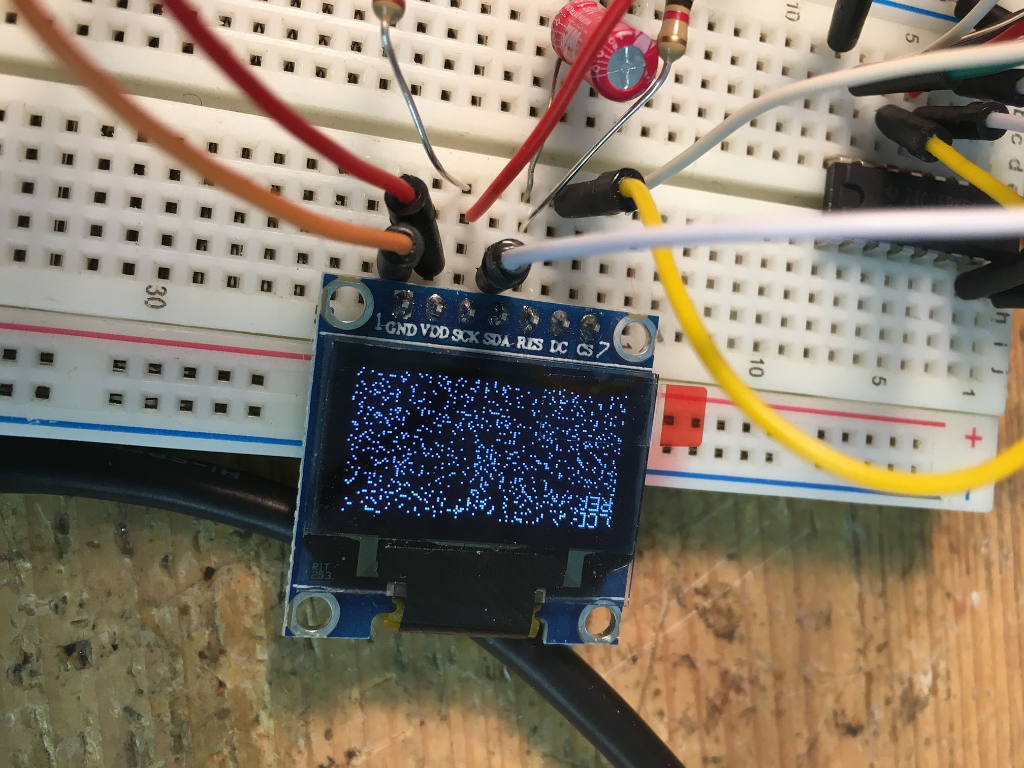
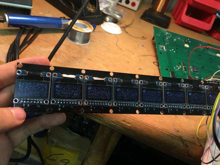
Hey people, I need you experienced guys! I've made a mios32-Core by myself which I test at the moment. While the first one works great. The second one causes trouble. And I don't know why. Please see the picture attached. Does anyone have an idea where the noise on the displays come from? I used this OLED-breakout (it contains OLEDs, Reset-circuits (Cap & Res) & Shiftregister) in some other projects already and it worked fine. So I assume the mistake is somewhere on the core. But as I said: Another identical core runs fine... Could it be the STM that is damaged? To be sure, that the mistake is not on the 9x OLED Breakout, I also tried it with an OLED with Reset and shiftregister on the breadboard. Same here... I now searched for about eight hours and also searched with an oscilloscope, but I was not able to locate the problem. Thank you very much! Best, Chris

-
Relocation of keybed from main board not working
FantomXR replied to Gregmidi's topic in MIDIfication
Yes! That's correct! -
Relocation of keybed from main board not working
FantomXR replied to Gregmidi's topic in MIDIfication
Hi and welcome to the forum! Well, to be honest I can not believe, that a ribbon cable with this length stops working completely. Are you sure that the ribbon cable has the correct orientation? I made this mistake often in the past. In general it's a twisted cable (one connector looks up, one connector looks down, cable straight). Pictures might help! -
I know that. But my use-case still is different and I don't like the big connector :-)
-
Yeah! It’s not “real” Ethernet. But it seems to be a great option! Everything in one Cable (In / Out / Power). I today finished the reverse engineering of the official GM5-PCB from ucapps. From there I’ll create my special PCB.
-
Although I have a RTP-OEM I will not use it in this case. I’ll use 2xGM5, which gives me 10 MIDI I/Os in total. I found that page which shows an easy way, how to transform MIDI into Ethernet and back to midi: https://www.edn.com/design/consumer/4368054/Send-MIDI-signals-over-long-distances Only a few parts are needed. Seems to be perfect because I still have some pins on the Ethernet-connector left to also transmit +5V and GND.
-
Not yet. But as I said: I don’t need classic midi in / miidi out. I need Ethernet :-)
-
Thanks for the link! This is not what I need. I need to make my own PCB because I'll integrate a circuit that allows transmitting MIDI over 50m via Ethernet. I'll just take two GM5 and I'm fine. That should work! :-)
-
Hey! Thanks! I just discovered, that Ploytec sells the GM5 in sets of 5 for 33€/5pc. I think I will take that solution!
-
Hey people, just a simple question: I have a use-case where I need 8 MIDI I/Os. Is this possible with the STM? What I read on ucapps is, that 4 I/Os are maximum. I wonder if there is an option to extend those MIDI I/Os. Thanks, Chris
-
Using a 405 instead of 407 makes no sense to me. 407 costs just 2€ more.
-
Do we need to adapt the firmware when using a smaller STM or can we use it as is?
-
So, how do we proceed? What are the next steps for this project?
-
And the next question would be: Why? Does someone run the STM-Core at its limits? The STM32F407 is a beast and powerful and maybe already an overkill for “just midi”. :-)
-
At first we should discuss the sense of that board. Should it be a pin-compatible replacement for the Core8? If yes, the feature-list is fixed. Adding SMD-optos is no problem. My MIDI-PCB is already full-SMD. Regarding PCB-manufacture: I order my PCBs at elecrow with very good results! So I'd suggest them. You asked me about 3V3: The PCB has a 3V3 power plane as well as a GND plane. In the wiki you wrote, that a programmer is needed. If I assemble those PCBs I'd program them with the MIOS bootloader so you don't have to do it. I'll have a look into my designs and see if I can upload another eagle-file which contains the newest core design (with SMD crystal, etc.) If having a small footprint the the main-goal in this design we should think about replacing the IDC headers with micromatch-headers. Smaller footprint and smaller connector-type on the cable-side.