FantomXR
-
Posts
1,035 -
Joined
-
Last visited
-
Days Won
22
Content Type
Profiles
Forums
Blogs
Gallery
Everything posted by FantomXR
-
I ask myself where at ponoko the smoked acryl is available. I cant find it. :) It looks nice...
-
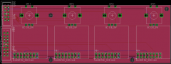
Here is a quick sketch of a possible 4x OLED layout. It has no mounting holes yet. The PCB could be cutted of if less than four displays are needed. I'm thinking about replacing the 10pin connector with a 16pin connector, to directly connect the core to one of this 4x_oled_module and add another connector on the other side that forwards the chip-select-lines which are not used on the first board. Would make sense I think,
-
-
-
From the album: Sketches
-
BTW: I have a LRE left... if someone wants one. It has 3mm red leds on it and also the encoders, but three are missing. Encoders are not detented and without switch. I'd unplug the ICs and keep them for other projects... but this one is ready2go.
-
Damn it! I just realized that other OLEDs have a totally different pinout and less pins (for smaller displays). Anyway... I'll keep you posted
-
And I wonder why you don't go with the new board of fairlightiii which has SMD LEDs on it and doesn't require any soldering on the LED-side.
-
Yes. But its up to the user if he wants 90 degree header or normal ones. Anyway: as long as nobody is able to confirm the schematic I won't go on with this project. Don't want to waste money...so fresh eyes on the layout could save time and money ... For everybody :-)
-
To me it sounds quite expensive. I tested seeed and elecrow a while ago. While it's difficult to communicate with the people from seeed, I have good experiences with elecrow. They offer: 10pc of green PCB in the size 10x10cm for $14,90. Shipping is $10 with airmail (7-24 days) and $25 with DHL (2-3 days). In the worst case I can get 4 carrier boards on one pcb (I think it will be 6... but... let's stay with the worst case) which makes a total of 40 boards. Total costs are $24,90 parted thru the numbers of PCBs we have a total of $0,63. This sounds good to me ;) It's even less if you do batch orders.
-
do you have a photo of that cut? The thing is, that a board, which has cut outs and is not quadratic, in the end is much more expensive. We want a low cost solution. I will make new pcbs today evening. Should I add the resistor and cap on the reset line to every display if I out four displays on one pcb?
-
Hahaha! Correct. :-)
-
"keyed" means a protection against plugging the cable in the wrong way? sure! They connectors should have that! The 1-row-connectors are nice because they use less space but you won't get ready2go cables which are longer than 30cm. This might be to less (at least in my cases). But like I said: If the basics are working I can adjust that for you :) The first pic you posted is exactly what I want to achieve (besides the connector which is used there).
-
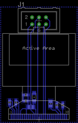
Short explanation: In Eagle blue connections are bottom and red connections are top layer. As you can see the SMD pins of the foilcable of the oled are blue, so bottom layer. I want to create a PCB where the connections on the foilcable are soldered to the bottom. Than of course fold it and glue the display to the top of the PCB. Eagle is not a 3D program so I can not add a "folded" foilcable. :smile: I created this oled after the datasheet. Your pic is not working at my side. What you mean by 7pin? The problem with this is, that there are no such cables available so you have to create them by yourself which is very time consuming. Midibox works with such ribbon connectors for years and it's proven to work the best. But you can adjust the layout after your needs (or I can do it, if you are not familiar with eagle) :)
-
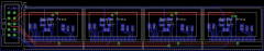
Sure! I just took the big one for 1:1 pinning to the core. It can be easily adapted. See this pic: Just a simple layout without mounting holes, etc. My plan is, to make three boards for now: 1x OLED, 4xOLED and 8xOLED. I think this should cover most usecases. To connect them to the core I'd also design an adapter board to use standard ribbon cable.
-
From the album: Sketches
-
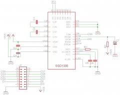
Okay! I created a package in eagle and set up a little schematic. Maybe one of you could take a look at it. This should work...
-
From the album: Sketches
-
No prob. I can create an eagle package by myself... but now I need to go to work at least for a few hours. :)
-
Another good thing we will run in by using a handmade design is, that (as far as I know) all OLEDs use the same fpc connector and the same pinning. So the PCB could be easily adapted to every size the MB-user needs. Okay, the layout should be really fast ready to go. I will look for an eagle file for such a display. But maybe one of you already got one? This will safe a lot of work.
-
I didn't get the last suggestion. What do you mean by mounting int on the small board? This looks nice too: http://www.exp-tech.de/sparkfun-redbot-kit The schematic is the same like the one on buydisplay. So this should work....
-
From the album: Sketches
-
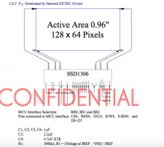
Okay, and as you see here: http://ucapps.de/mbhp/mbhp_lcd_ssd1306_single_mios32.pdf TK added a resistor and a cap too. //edit: See this schematic: BS0, BS1 and BS2 will go to GND and I would also ground every unused pin.
-
Of course it looks kind of nice. But it will need special lables. Anyway: nice design. But that's covered in another thread.
-
Thanks! Yes but I don't know if this is the correct one. Are you sure that I don't want to go with with "Vcc generates externally"-schematic? I want to start it today evening. Btw: If we go with this solution, it would be also possible to use oleds in a smaller size. Maybe this is a solution for your MBProgrammer?
-
I have 15 of those oleds by myself :-) But a schematic would be more safe.