FantomXR
Members-
Posts
1,035 -
Joined
-
Last visited
-
Days Won
22
Content Type
Profiles
Forums
Blogs
Gallery
Everything posted by FantomXR
-
Hey TK, it works great! Thank you very much! ;-) I try to understand how the midi-ports are set. It works via a hex-number but I don't get how this hex-number gets calculated. Could you please give me a short explanation about it? This would be awesome :-) All the best! Chris
-
Thanks for the quick change! I'll check it out in the next hour ;-) Of course I'd need to reconfigure the keyboard. Are the changes also already made in the svn? If yes I could compile my own firmware, which has the delay_slowest_black_keys integrated. Thanks again!
-
Dear Thorsten, thanks for the quick answer! I thought, that it might be possible to enhance the KB-app with two more analog inputs, so all 8 inputs of an AINSER can be used.
-
MIDIboxKB has a better velocity resolution. That's why I ask.
-
Hey Folks, just a short question: Is there a support for a AINSER8 in the MIDIboxKB or is it planned to be implemented? Thanks! Chris
-
Alternative to LED encoder rings: illuminated red-green encoders?
FantomXR replied to latigid on's topic in Design Concepts
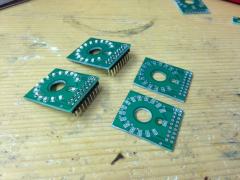
My grid on the encoder PCB is 29mm. This is because I want to add OLEDs underneath it and they have a width of 27,3mm. My encoder pcb can be stacked with a SMD LED-Ring (0805) which has 16 LEDs. Maybe I'll add the support for those RGB-Encoders. -
Alternative to LED encoder rings: illuminated red-green encoders?
FantomXR replied to latigid on's topic in Design Concepts
Hey Novski, I checked your website again. I saw that you use LED-Rings as well. So for what purpose do you use the LEDs which are integrated in the encoder? -
Alternative to LED encoder rings: illuminated red-green encoders?
FantomXR replied to latigid on's topic in Design Concepts
It's all about the quantity. I don't think that this is very expensive if I order 1.000 pc of pcb assembled LED-ring-PCBs. But what should I do with 1.000 pc? :D Anyway: Your concept sounds great. -
If you look for cheap OLEDs, check aliexpress. You can get the OLEDs which are working nice for even less money. Here are some examples: Blue, 0.96": http://www.aliexpress.com/item/1Pcs-blue-128X64-OLED-LCD-LED-Display-Module-0-96-I2C-IIC-SPI-Serial-new-original/32328394682.html White, 0.96": http://www.aliexpress.com/item/0-96-inch-7PIN-White-OLED-Display-Module-SSD1306-Drive-IC-SPI-Interface/32387186587.html White, 1.3": http://www.aliexpress.com/item/White-1-3-SPI-Serial-128X64-OLED-LCD-LED-Display-Module-for-Arduino-UNO-R3/2031225102.html
-
I checked again: I have a LPC1769 core which I tested with the iTrack. Result: It's working perfectly while the STM32F3 doesn't..... So the STM32F4 seems to be different from that and the issue is not (only) related to MIOS32 & the iTrack. Anyway: The LPC is working and that are great news :-)
-
Thanks for the reply! After reading more about this I just realized that many people have the same problem. So it seems it's related to the iTrack...sadly :( I'd need to use a USB to MIDI Adapter but with that I'm not able to power the MIDIbox directly...
-
Okay, that's wired... I have the same problem! I just bought an iTrack Dock of Focusrite which has an USB-jack on the backside. This is for connecting USB-MIDI-Devices directly. I tested it with a iCon iKeyboard which works well. But when connecting a MIDIbox, it's not recognized by the iTrack Dock at all. I disabled multiple USB-support and also tried different names... the MIDIbox get's powered externally so it's not a problem related to the power supply of the iTrack. It doesn't work either if I try to power the MIDIbox from the iTrack directly. It boots up but doesn't get recognized. Any suggestions?
-
And also some hosts have problems with the multiple usb-port function. Try to set single_usb to 1 in the bootloader.
-
Hey people, I'm looking for a source for pitchwheels or modulation wheels. I know that FATAR has some and also Doepfer sells them. But I'm looking for smaller ones because the other take a lot of space in a little controller... especially the depth is important. Look at korg microkorg f.e. These are great ;) Thanks! Chris
-
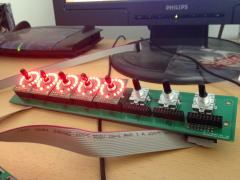
Haha! I'm curious about it ;) But as you said already: It's not clear if those PCBs will be available in the future. If I have my layout running, I will post everything online... so you could reproduce them if you want to. But: SMD soldering skills are required! BTW: Resistors are not required... I tried it and the LEDs are working well. Done! This should work: This is the LED-PCB. It doesnt need any mounting holes because you can stack it directly on the encoder. The encoder PCB would have some mounting holes and of course you can mount the encoder at the panel directly. 2x 74HC595 and 1x ULN 2803 SMD on board. With the 2x8 connector at the bottom you can forward the led-inputs to another LED-PCB. With the jumper in the top right you can skip IC2 and IC3.... so a 16x16 configuration is possible!
-
As far as I know the limit of SR is at 32 for DIN (which means 32*8=256 inputs = 128 encoder) and 32 for DOUT (three SR needed in my config for the LEDrings... so 10 PCBs in total = 80 LED Rings).... am I wrong? Of course there will be a lot more possible in a 16x16 design. :-) Ah ! Well... I can think about a connection possibilty between the 8x1 modules so that also a 16x16 config would be possible...
-
Hm, I don't see the reason, why we are "forced" to use a 8x2 design and not a 8x1 like I do. This should also lead to more brightness on the LED-side (8x16 instead of 16x16). The PCBs can also be chained of course. I didn't check it out yet, but I could create a displayboard that holds displays in this 45° angle. This can be easily mounted under the 8x1 encoder board on a panel. I think all in all this would lead to more flexibility in design and is also easy to set up. Anyway: Keep it up ;) A question regarding your configuration: If you move an encoder, is the value displayed in the OLED or is it "just" visible on the LED ring so the OLED keeps its label?
-
As far as I know it's not possible to mix up different display-types in an application. I'm right now in designing a new board. The board has different parts. There is a "base-PCB" which contains the encoder and also the shiftregisters for DIN. Than there is another PCB which is stacked on those encoders. This contains the LEDs (0805 SMD LED) and also the SR for DOUT as well as the ULN. All SMD. Each PCB handles 8 encoders and not 16 like in the LRE. So there would be enough space between two modules to add LCDs... but I'm open for suggestions. BTW: If I have this running it would be quite easy to change it into a 1x4 module.
-
Hi Peter, yesterday I had a conversation with a friend / colleague of mine, also musician. We talked about the moog-series... and also the little phatty. It sounds interesting what you build for it. Do you btw have a picture of your complete MBprogramma? I'd like to help you. What do you need regarding the displays in detail?
-
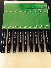
To assemble the OLED PCB you definately would need a very good soldering iron, because the pitch of the OLED-foil is 0.7mm. I have a very good soldering iron with an SMD tip... but anyway it's pretty difficult. I think there is no option to solder them in an reflow oven. There are also no FPC connectors for this pitch... unfortunately. But the first step is done: The OLEDs are working. With that said any kind of combination is possible and an adaption to the LRE should be pretty easy. BTW: I also created an encoder board where you can put LED rings on it. See here: And of course the space between the OLEDs is exactly the same as for the encoders. That was my goal. The encoder board has no shiftregisters on it. So you would need a DIN and DOUT module. Maybe I'll add this!


