

FantomXR
-
Posts
1,035 -
Joined
-
Last visited
-
Days Won
22
Content Type
Profiles
Forums
Blogs
Gallery
Posts posted by FantomXR
-
-
Yes. I still have some boards. Not soldered yet but I could do it. Pls drop me a message if interested.
-
I tried it now with a fresh firmware. I cloned the GitHub to get the latest version. Then I've copy/pasted the changes @TK. made into the code and compiled.
I use the core and a classic AINSER8 module. PB8 goes directly from the discovery-board to a breadboard. There is a pullup resistor to 5V. PB8 goes into the CS-input. Result: It's working fine.
If I now just change PB8 to PE8 (like in your example), nothing happens. Here is my NGC:
RESET_HW


AINSER n=1 enabled=1 cs=1 resolution=7bit num_pins=1 muxed=0
AINSER n=2 enabled=1 cs=2 resolution=7bit num_pins=1 muxed=0
Have you an idea?!
-
Okay. I tried with a MIDIbox Core. Same: It's not working. Nothing happens... any help on this?!
-
Ah, no. It's SMD soldered. So, traces are given.
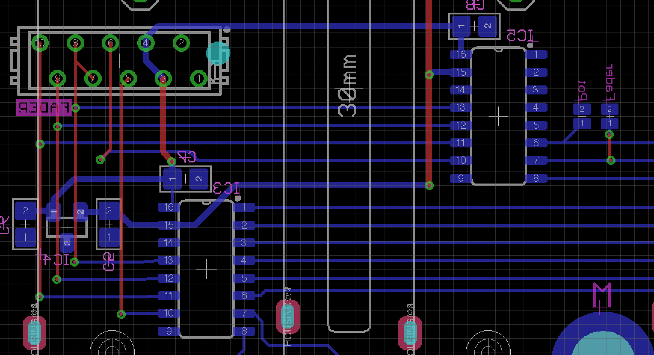
But I double-checked the schematic and all looks well. Here is the excerpt from the PCB layout:
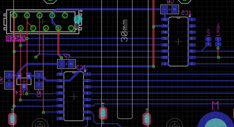
Pin 6 of the connector comes from PE6 of the STM. The rest is the same as on the other MCP.
-
Invert?! What do you mean with that?
-
Yes. I did. I see the pulses on the CS line.
-
57 minutes ago, Antichambre said:
Do you test it without the NG with a regular app first?
No. As I don't use any other app and I stated above that I want to use it in NG TK surely took care of it.
This is ainser.c:
// $Id$
//! \defgroup AINSER
//!
//! AINSER module driver
//!
//! \{
/* ==========================================================================
 *
 *  Copyright (C) 2011 Thorsten Klose (tk@midibox.org)
 *  Licensed for personal non-commercial use only.
 *  All other rights reserved.
 *
 * ==========================================================================
 */

/////////////////////////////////////////////////////////////////////////////
// Include files
/////////////////////////////////////////////////////////////////////////////

#include <mios32.h>

#include "ainser.h"


/////////////////////////////////////////////////////////////////////////////
// Local variables
/////////////////////////////////////////////////////////////////////////////

static u8 num_used_modules = AINSER_NUM_MODULES;
static u8 ainser_enable_mask;
static u8 ainser_muxed_mask;
static u8 num_used_pins[AINSER_NUM_MODULES];

static u16 ain_pin_values[AINSER_NUM_MODULES][AINSER_NUM_PINS];
static u16 previous_ain_pin_value;

static u8 ain_deadband[AINSER_NUM_MODULES];


/////////////////////////////////////////////////////////////////////////////
// Local Prototypes
/////////////////////////////////////////////////////////////////////////////

static s32 AINSER_SetCs(u8 module, u8 value);


/////////////////////////////////////////////////////////////////////////////
//! Initializes AINSER driver
//! Should be called from Init() during startup
//! \param[in] mode currently only mode 0 supported
//! \return < 0 if initialisation failed
/////////////////////////////////////////////////////////////////////////////
s32 AINSER_Init(u32 mode)
{
    s32 status = 0;
    int module, pin;

    // currently only mode 0 supported
    if( mode != 0 )
        return -1; // unsupported mode

#if AINSER_SPI_OUTPUTS_OD
    // pins in open drain mode (to pull-up the outputs to 5V)
    status |= MIOS32_SPI_IO_Init(AINSER_SPI, MIOS32_SPI_PIN_DRIVER_STRONG_OD);
#else
    // pins in push-poll mode (3.3V output voltage)
    status |= MIOS32_SPI_IO_Init(AINSER_SPI, MIOS32_SPI_PIN_DRIVER_STRONG);
#endif

    // extra CS pin
#if AINSER_NUM_MODULES >= 3
    MIOS32_BOARD_J10_PinInit(14, MIOS32_BOARD_PIN_MODE_OUTPUT_OD);
#endif

    // SPI Port will be initialized in AINSER_Update()

    num_used_modules = AINSER_NUM_MODULES;
#if AINSER_NUM_MODULES > 8
# error "If more than 8 AINSER_NUM_MODULES should be supported, the ainser_enable_mask variable type has to be changed from u8 to u16 (up to 16) or u32 (up to 32)"
#endif
#if AINSER_NUM_MODULES > 8
# error "If more than 8 AINSER_NUM_MODULES should be supported, the ainser_muxed_mask variable type has to be changed from u8 to u16 (up to 16) or u32 (up to 32)"
#endif

    for(module=0; module<AINSER_NUM_MODULES; ++module) {
        num_used_pins[module] = AINSER_NUM_PINS;

        // ensure that CS is deactivated
        AINSER_SetCs(module, 1);

        AINSER_EnabledSet(module, 1);
        AINSER_MuxedSet(module, 1);
        AINSER_NumPinsSet(module, AINSER_NUM_PINS);
        AINSER_DeadbandSet(module, MIOS32_AIN_DEADBAND);

        // clear all values
        for(pin=0; pin<AINSER_NUM_PINS; ++pin) {
            ain_pin_values[module][pin] = 0;
        }
        previous_ain_pin_value = 0;
    }

    return status;
}


/////////////////////////////////////////////////////////////////////////////
//! \return the number of modules which are scanned
/////////////////////////////////////////////////////////////////////////////
s32 AINSER_NumModulesGet(void)
{
    return num_used_modules;
}

/////////////////////////////////////////////////////////////////////////////
//! Sets the number of modules which should be scanned
//! \return < 0 on error (e.g. unsupported number of modules)
/////////////////////////////////////////////////////////////////////////////
s32 AINSER_NumModulesSet(u8 num_modules)
{
    if( num_modules >= AINSER_NUM_MODULES )
        return -1;

    num_used_modules = num_modules;

    return 0; // no error
}

/////////////////////////////////////////////////////////////////////////////
//! \return the enable mask for modules which should be scanned
/////////////////////////////////////////////////////////////////////////////
s32 AINSER_EnabledGet(u8 module)
{
    if( module >= AINSER_NUM_MODULES )
        return 0;

    return (ainser_enable_mask & (1 << module)) ? 1 : 0;
}

/////////////////////////////////////////////////////////////////////////////
//! Sets the enable mask for modules which should be scanned
/////////////////////////////////////////////////////////////////////////////
s32 AINSER_EnabledSet(u8 module, u8 enabled)
{
    if( module >= AINSER_NUM_MODULES )
        return -1; // invalid module

    if( enabled )
        ainser_enable_mask |= (1 << module);
    else
        ainser_enable_mask &= ~(1 << module);

    return 0; // no error
}


/////////////////////////////////////////////////////////////////////////////
//! \retval 0 if 1-to-8 multiplexers disabled for the given module
//! \retval 1 if 1-to-8 multiplexers enabled for the given module (default)
/////////////////////////////////////////////////////////////////////////////
s32 AINSER_MuxedGet(u8 module)
{
    if( module >= AINSER_NUM_MODULES )
        return 0;

    return (ainser_muxed_mask & (1 << module)) ? 1 : 0;
}

/////////////////////////////////////////////////////////////////////////////
//! Enables/disables the 1-to-8 multiplexer handling.\n
//! Use muxed=0 for AINSER8 module, and muxed=1 for AINSER64 module (default)
/////////////////////////////////////////////////////////////////////////////
s32 AINSER_MuxedSet(u8 module, u8 muxed)
{
    if( module >= AINSER_NUM_MODULES )
        return -1; // invalid module

    if( muxed )
        ainser_muxed_mask |= (1 << module);
    else
        ainser_muxed_mask &= ~(1 << module);

    return 0; // no error
}


/////////////////////////////////////////////////////////////////////////////
//! \return the number of AIN pins per module which are scanned
/////////////////////////////////////////////////////////////////////////////
s32 AINSER_NumPinsGet(u8 module)
{
    if( module >= AINSER_NUM_MODULES )
        return 0; // invalid module (return 0 pins)

    return num_used_pins[module];
}

/////////////////////////////////////////////////////////////////////////////
//! Sets the number of AIN pins per module which should be scanned
//! \return < 0 on error (e.g. unsupported number of pins)
/////////////////////////////////////////////////////////////////////////////
s32 AINSER_NumPinsSet(u8 module, u8 num_pins)
{
    if( module >= AINSER_NUM_MODULES )
        return -1; // invalid module

    if( num_pins > AINSER_NUM_PINS )
        return -2;

    num_used_pins[module] = num_pins;

    return 0; // no error
}


/////////////////////////////////////////////////////////////////////////////
//! \return the deadband which is used to notify changes
//! \return < 0 on error
/////////////////////////////////////////////////////////////////////////////
s32 AINSER_DeadbandGet(u8 module)
{
    if( module >= AINSER_NUM_MODULES )
        return 0; // invalid module (return 0)

    return ain_deadband[module];
}

/////////////////////////////////////////////////////////////////////////////
//! Sets the difference between last and current pot value which has to
//! be achieved to trigger the callback function passed to AINSER_Handler()
//! \return < 0 on error
/////////////////////////////////////////////////////////////////////////////
s32 AINSER_DeadbandSet(u8 module, u8 deadband)
{
    if( module >= AINSER_NUM_MODULES )
        return -1; // invalid module

    ain_deadband[module] = deadband;

    return 0; // no error
}


/////////////////////////////////////////////////////////////////////////////
//! \return the AIN pin value of the given module and pin
//! \return < 0 if wrong module or pin selected!
/////////////////////////////////////////////////////////////////////////////
s32 AINSER_PinGet(u8 module, u8 pin)
{
    if( module >= AINSER_NUM_MODULES )
        return -1;

    if( pin >= AINSER_NUM_PINS )
        return -1;

    return ain_pin_values[module][pin];
}


/////////////////////////////////////////////////////////////////////////////
//! \return the previous value of the pin which has triggered the NotifyChanged hook.\n
//! Only valid when function is called from this hook!
/////////////////////////////////////////////////////////////////////////////
s32 AINSER_PreviousPinValueGet(void)
{
    return previous_ain_pin_value;
}


/////////////////////////////////////////////////////////////////////////////
//! This function should be periodically called to scan AIN pin changes.
//!
//! A scan of a single multiplexer selection takes ca. 50 uS on a LPC1769 with MIOS32_SPI_PRESCALER_8
//!
//! Whenever a pin has changed, the given callback function will be called.\n
//! Example:
//! \code
//!   void AINSER_NotifyChanged(u32 pin, u16 value);
//! \endcode
//! \param[in] _callback pointer to callback function
//! \return < 0 on errors
/////////////////////////////////////////////////////////////////////////////
s32 AINSER_Handler(void (*_callback)(u32 module, u32 pin, u32 value))
{
    // the mux_ctr -> pin mappin is layout dependend
    //const u8 mux_pin_map[8] = {0, 1, 2, 3, 4, 5, 6, 7 };
    //const u8 mux_pin_map[8] = {1, 4, 3, 5, 2, 7, 0, 6 }; // reversed pins
    const u8 mux_pin_map[8] = {6, 3, 4, 2, 5, 0, 7, 1 }; // order of MUX channels
    static u8 mux_ctr = 0; // will be incremented on each update to select the next AIN pin
    static u8 first_scan_done = 0;
    static u16 link_status_ctr = 0;
    s32 status = 0;

    // init SPI port for fast frequency access
    // we will do this here, so that other handlers (e.g. AOUT) could use SPI in different modes
    // Maxmimum allowed SCLK is 2 MHz according to datasheet
    // We select prescaler 64 @120 MHz (-> ca. 500 nS period)
    status |= MIOS32_SPI_TransferModeInit(AINSER_SPI, MIOS32_SPI_MODE_CLK0_PHASE0, MIOS32_SPI_PRESCALER_64);

    // determine next MUX selection
    int next_mux_ctr = (mux_ctr + 1) % 8;

    // link LED will flash with PWM effect
    ++link_status_ctr;
    const u32 pwm_period = 20;       // *1 mS -> 20 mS
    const u32 pwm_sweep_steps = 100; // *20 mS -> 2000 mS
    u32 pwm_duty = ((link_status_ctr / pwm_period) % pwm_sweep_steps) / (pwm_sweep_steps/pwm_period);
    if( (link_status_ctr % (2*pwm_period*pwm_sweep_steps)) > pwm_period*pwm_sweep_steps )
        pwm_duty = pwm_period-pwm_duty; // negative direction each 20*25 ticks
    u32 link_status = ((link_status_ctr % pwm_period) > pwm_duty) ? 1 : 0;

    // loop over connected modules
    int module;
    u32 module_mask = 1;
    for(module=0; module<num_used_modules; ++module, module_mask <<= 1) {

        if( !(ainser_enable_mask & module_mask) )
            continue;

        u8 muxed = ainser_muxed_mask & module_mask;

        // loop over channels
        int chn;
        for(chn=0; chn<8; ++chn) {
            // CS=0
            status |= AINSER_SetCs(module, 0);

            // retrieve conversion values
            // shift in start bit + SGL + MSB of channel selection, shift out dummy byte
            MIOS32_SPI_TransferByte(AINSER_SPI, 0x06 | (chn>>2));
            // shift in remaining 2 bits of channel selection, shift out MSBs of conversion value
            u8 b1 = MIOS32_SPI_TransferByte(AINSER_SPI, chn << 6);
            // shift in mux_ctr + "Link LED" status to 74HC595, shift out LSBs of conversion value
            u8 b2 = MIOS32_SPI_TransferByte(AINSER_SPI, ((chn == 7 ? next_mux_ctr : mux_ctr) << 5) | link_status);

            // CS=1 (the rising edge will update the 74HC595)
            AINSER_SetCs(module, 1);

            // store conversion value if difference to old value is outside the deadband
            u16 pin = muxed ? (mux_pin_map[mux_ctr] + 8*(7-chn)) : (7-chn); // the mux/chn -> pin mapping is layout dependend
            u16 value = (b2 | (b1 << 8)) & 0xfff;
            previous_ain_pin_value = ain_pin_values[module][pin];
            int diff = value - previous_ain_pin_value;
            int abs_diff = (diff > 0 ) ? diff : -diff;

            if( !first_scan_done || abs_diff > ain_deadband[module] ) {
                ain_pin_values[module][pin] = value;

                // notify callback function
                // check pin number as well... just to ensure
                if( first_scan_done && _callback && pin < num_used_pins[module] )
                    _callback(module, pin, value);
            }
        }
    }

    // select MUX input
    mux_ctr = next_mux_ctr;

    // one complete scan done?
    if( next_mux_ctr == 0 )
        first_scan_done = 1;

    return 0; // no error
}


/////////////////////////////////////////////////////////////////////////////
// Internal function to set CS line depending on module
/////////////////////////////////////////////////////////////////////////////
static s32 AINSER_SetCs(u8 module, u8 value)
{
    switch( module ) {
        case 0: return MIOS32_SPI_RC_PinSet(AINSER_SPI, AINSER_SPI_RC_PIN_MODULE1, value); // spi, rc_pin, pin_value
        case 1: return MIOS32_SPI_RC_PinSet(AINSER_SPI, AINSER_SPI_RC_PIN_MODULE2, value); // spi, rc_pin, pin_value
        case 2: return MIOS32_BOARD_J10_PinSet(14, value);

#if AINSER_NUM_MODULES > 3
# error "CS Line for more than 3 modules not prepared yet - please enhance here!"
#endif
    }


    return -1;
}


//! \}
and in mios32_config.h I set
#define AINSER_NUM_MODULES 3So, it should be exactly the same as in TKs branch.
-
-
Hey @TK.,
I tried it without success. I copied the code from you into my firmware.
My NGC file looks like this:
RESET_HW

AINSER n=1 enabled=1 num_pins=1 cs=1 resolution=7bit
AINSER n=2 enabled=1 num_pins=1 cs=2 resolution=7bit
I have a potentiometer connected to the first analog input of the second and another one to the first input of the third module. The first module is not used at the moment.
If I "set debug on" in the terminal, I see movements if I turn the potentiometer which is connected to the second module. Anyway I can not see anything when I turn the pot which is connected to the third module.
I've tried both PP and OD mode (with 1k pullup to 5V). I use PE6, which should lead to
MIOS32_BOARD_J10_PinInit(14, MIOS32_BOARD_PIN_MODE_OUTPUT_OD)and
case 2: return MIOS32_BOARD_J10_PinSet(14, value);Any ideas what I do wrong?
-
Yes!
Drop me a PM.
-
I'd strongly recommend to not use "normal" LEDs. It's much easier to use WS2812 RGB LEDs. Only one single data-line needed instead of 11 (in your case). And routing LED-matrix on a PCB is cumbersome....
Apart from that I can not answer your question...
-
8 hours ago, weasel said:
oh also for that amount of OLEDs and input stuff you might need a couple more MCUs/core boards down the line i think?
MB_NG supports up to 64 OLEDs from just one core ;-)
-
1 hour ago, latigid on said:
(I think) 60€
It's actually 50€.
@otropomhow much do you need of each? I need something from mouser as well and maybe it makes sense to combine both orders...
-
It's just one line of code in the firmware. So you have to compile the firmware by yourself.
Please note that both devices need to be powered from the same power source.
-
Thank you very much!
I'll give it a try.
-
I did some tests with this.
I connected a DIO-Board to my keyboard and the DIO-board to the core with jumper wire => no HCT541. I powered the DIO with 3V3 from the DISCO-Board. The result: It's running fine. No issues. I checked the clock with my oscilloscope. It looks very clean. Also no issues here.
So, I think I'll leave away the HCT541 for my applications and run everything from 3V3.
//edit: I've connected an encoder to the DIO-board. Works also fine.
-
14 hours ago, TK. said:
E.g. let's assume that J10.D0 is unused so far, then add to AINSER_Init():
Dear TK,
I undo all changes and added the lines as you suggested. Unfortunately I can not get it working.
I edited the ainser.h like this:
s32 AINSER_Init(u32 mode)
{
  MIOS32_BOARD_J10_PinInit(0, MIOS32_BOARD_PIN_MODE_OUTPUT_PP);

  s32 status = 0;
  int module, pin;

  // currently only mode 0 supported
  if( mode != 0 )
    return -1; // unsupported mode

#if AINSER_SPI_OUTPUTS_OD
  // pins in open drain mode (to pull-up the outputs to 5V)
  status |= MIOS32_SPI_IO_Init(AINSER_SPI, MIOS32_SPI_PIN_DRIVER_STRONG_OD);
#else
  // pins in push-poll mode (3.3V output voltage)
  status |= MIOS32_SPI_IO_Init(AINSER_SPI, MIOS32_SPI_PIN_DRIVER_STRONG);
#endif

  // SPI Port will be initialized in AINSER_Update()

  num_used_modules = AINSER_NUM_MODULES;
#if AINSER_NUM_MODULES > 8
# error "If more than 8 AINSER_NUM_MODULES should be supported, the ainser_enable_mask variable type has to be changed from u8 to u16 (up to 16) or u32 (up to 32)"
#endif
#if AINSER_NUM_MODULES > 8
# error "If more than 8 AINSER_NUM_MODULES should be supported, the ainser_muxed_mask variable type has to be changed from u8 to u16 (up to 16) or u32 (up to 32)"
#endif

  for(module=0; module<AINSER_NUM_MODULES; ++module) {
    num_used_pins[module] = AINSER_NUM_PINS;

    // ensure that CS is deactivated
    AINSER_SetCs(module, 1);

    AINSER_EnabledSet(module, 1);
    AINSER_MuxedSet(module, 1);
    AINSER_NumPinsSet(module, AINSER_NUM_PINS);
    AINSER_DeadbandSet(module, MIOS32_AIN_DEADBAND);

    // clear all values
    for(pin=0; pin<AINSER_NUM_PINS; ++pin) {
      ain_pin_values[module][pin] = 0;
    }
    previous_ain_pin_value = 0;
  }

  return status;
}


[]


static s32 AINSER_SetCs(u8 module, u8 value)
{
  switch( module ) {
  case 0: return MIOS32_SPI_RC_PinSet(AINSER_SPI, AINSER_SPI_RC_PIN_MODULE1, value); // spi, rc_pin, pin_value
  case 1: return MIOS32_SPI_RC_PinSet(AINSER_SPI, AINSER_SPI_RC_PIN_MODULE2, value); // spi, rc_pin, pin_value
  case 2: return MIOS32_BOARD_J10_PinSet(0, value);

#if AINSER_NUM_MODULES > 3
# error "CS Line for more than 2 modules not prepared yet - please enhance here!"
#endif
  }
But when I now connect the Chipselect to PE8, which is D0 on J10A, nothing happens.
Any idea?
Thanks,
Chris -
Thanks for chiming in!
Is it really so easy? :-) Thanks! I'll try it!!
-
I've made it already :-)
9x Encoders + 1 Potentiometer for master-volume
9x OLEDs
9x Faders
3x9 Button-rows
9x RGBLED-bars next to the faders
9x RGBLED underneath each encoderI don't need anything more!
-
Of course there are tons of other ICs, that are very usable but are not supported by MIDIbox though a dedicated driver is needed.
I thought that the STP may can be used with very little changes in the firmware but giving a great benefit. TLC5958 is a complete other story I think.
-
Isn't it 5-90mA per channel?
-
11 minutes ago, Zam said:
Ok, the logic is "0, 1 or 2 for SPI2 (J19:RC1, J19:RC2, J5A:A0(nowRC3) )", I have something else(wrong) in mind sorry.
This seems to be a good hint! Thanks!
Maybe @TK. could guide us in the right direction! :-)
-
2 hours ago, Zam said:
Are you sure about the pin value here?
No but I followed up the logic in the code above:
// Which RC pin of the SPI port should be used for the first module
// allowed values: 0 or 1 for SPI0 (J16:RC1, J16:RC2), 0 for SPI1 (J8/9:RC), 0 or 1 for SPI2 (J19:RC1, J19:RC2)
#ifndef AINSER_SPI_RC_PIN_MODULE1
#define AINSER_SPI_RC_PIN_MODULE1 0
#endif

// Which RC pin of the SPI port should be used for the second module
// allowed values: 0 or 1 for SPI0 (J16:RC1, J16:RC2), 0 for SPI1 (J8/9:RC), 0 or 1 for SPI2 (J19:RC1, J19:RC2)
#ifndef AINSER_SPI_RC_PIN_MODULE2
#define AINSER_SPI_RC_PIN_MODULE2 1
#endif

// Which RC pin of the SPI port should be used for the third module
// allowed values: 0 or 1 for SPI0 (J16:RC1, J16:RC2), 0 for SPI1 (J8/9:RC), 0 or 1 for SPI2 (J19:RC1, J19:RC2)
#ifndef AINSER_SPI_RC_PIN_MODULE3
#define AINSER_SPI_RC_PIN_MODULE3 2
2 hours ago, Zam said:also did you define modules number ? (ainser.h)
Not in ainser.h, but in the mio32_config.h with:
// enable three AINSER modules
#define AINSER_NUM_MODULES 3
2 hours ago, Zam said:and ainser.c
Sure! I did this:
static s32 AINSER_SetCs(u8 module, u8 value) { switch( module ) { case 0: return MIOS32_SPI_RC_PinSet(AINSER_SPI, AINSER_SPI_RC_PIN_MODULE1, value); // spi, rc_pin, pin_value case 1: return MIOS32_SPI_RC_PinSet(AINSER_SPI, AINSER_SPI_RC_PIN_MODULE2, value); // spi, rc_pin, pin_value case 2: return MIOS32_SPI_RC_PinSet(AINSER_SPI, AINSER_SPI_RC_PIN_MODULE3, value); // spi, rc_pin, pin_value #if AINSER_NUM_MODULES > 3 # error "CS Line for more than 2 modules not prepared yet - please enhance here!" #endif } -
Hey people,
a friend of mine just told me about the STP16CPC. It looks great. It can be accessed via SPI, it has 16 outputs and a current-setting. So if one would like to build LED-Rings this looks like a great solution with very less parts-count. You wouldn't need any current-limiting resistors in front of the LEDs and only one IC to drive 16 LEDs.
So, does anyone used this IC before and does it work in a classic DIO-chain without changes on the code?I took a look into the datasheet but I'm not sure. The STP has a LE-input which the HC595 doesn't have. But it might work if one connect the chipselect (RC) which is normally connected to RCLK on the HC595 to the LE of the STP.
Thanks,
Chris
Make NG listen to all banks?
in MIDIbox NG
Posted
Hey people,
In general I work with different banks. One thing that bothers me since starting working with NG is that it doesn't listen to all banks at the same time. So if I dump values to the midibox it only listens to the bank that it just activated. All other banks do not refresh.
Is there a chance that this will be possible in the future?
Thanks,
Chris