

FantomXR
-
Posts
1,035 -
Joined
-
Last visited
-
Days Won
22
Content Type
Profiles
Forums
Blogs
Gallery
Posts posted by FantomXR
-
-
Dear Bruno,
no I didn't try them.
Actually they are located in the Netherlands as far as I know.I order all my stuff at elecrow in China. Fast, reliable and very cheap.
-
Hey people,
for those of you who are looking for a nice online gerber view, I can recommend AISLER:
https://aisler.netYou can either upload the gerber files, but they do accept also right away eagle-brd.-files which makes it very easy to visualize it.
Prices seem a bit expensive. But anyway: for visualizing the PCB this is the best tool I've ever seen.
Best,
Chris -
A while ago I ordered those midi connectors and I’m happy with it.
https://de.aliexpress.com/item/-/32832191248.html
anyway: I think it’s hard to tell if those connectors are good or not. They look good and they feel nice. The midi plug has a tight fit. But apart from that? How should they differ from Kycon?
If you want I could send you a few samples of those. I ordered 50pc a few weeks ago.
-
Hm...
I know how to create a meta-command. But I don't know how to refer to a timer within a meta-command. Maybe you could explain how to set up a simple timer and I'll see if I can implement that?
Thanks,
Chris -
Do you send single note off events?
This is not necessary. I assume that Thorsten took care of the classical MIDI implementation.
If you send CC #123 from NG to KB, KB should interpret this as "All notes off". This should speed up the process significantly. -
Not without programming a timer in RTOS.
-
Hm, good point!
I tried to implement such thing via RTOS... but this seems to be above my skills. -
You could also do a "fade":
if ^section == 2 if BUTTON:1 == 127 set LED:2000 127 endif if BUTTON:1 == 0 set LED:2000 0 endif if LED:2000 == 127 set LED:1 20 set LED:1 20 delay_ms 20 set LED:1 25 delay_ms 20 set LED:1 30 delay_ms 20 set LED:1 35 delay_ms 20 set LED:1 40 delay_ms 20 set LED:1 45 delay_ms 20 set LED:1 50 delay_ms 20 set LED:1 55 delay_ms 20 set LED:1 60 delay_ms 20 set LED:1 64 delay_ms 20 set LED:1 60 delay_ms 20 set LED:1 55 delay_ms 20 set LED:1 50 delay_ms 20 set LED:1 45 delay_ms 20 set LED:1 40 delay_ms 20 set LED:1 35 delay_ms 20 set LED:1 30 delay_ms 20 set LED:1 25 delay_ms 20 set LED:1 20 delay_ms 20 exec_meta RunSection:2 endif if LED:2000 == 0 set LED:1 20 endif endif -
Hey people,
I don't have a question but I want to share this code.
I searched for a way to get a blinking LED within NG. Here is what it looks like:EVENT_BUTTON id=1 type=meta meta=runsection:2 button_mode=Toggle EVENT_LED id=1 dimmed=1 EVENT_LED id=2000And this is the NGR-part:
if ^section == 2

  if BUTTON:1 == 127
    set LED:2000 127
  endif

  if BUTTON:1 == 0
    set LED:2000 0
  endif

  if LED:2000 == 127
    set LED:1 64
    delay_ms 150
    set LED:1 20
    delay_ms 150
    exec_meta RunSection:2
  endif

  if LED:2000 == 0
    set LED:1 20
  endif

endif
What it does is: It checks the status of the button 1. Please note that the button is set to "toggle"-mode. If it's 127, LED:2000 which just acts as a value-storage is set to 127 and if that LED is 127, the loop is started. At the beginning of that loop the button-status is checked and as soon as it's 0, the loop stops.
Best,
Chris -
I solved it!
This is the NGC part:
EVENT_BUTTON id=1 type=meta meta=runsection:1 button_mode=OnOff if_equal=127And this is the NGR part:
if ^section == 1

    delay_ms 500

    if BUTTON:1 == 127
      SEND CC USB1 1 1 127
      exit
    endif

    if BUTTON:1 == 0
      SEND CC USB1 1 2 0
      exit
    endif

endif
This code wait's 500ms and checks if the button is still pressed. If yes it sends on channel 1, if not it sends on channel 2.
-
1 hour ago, Antichambre said:
If you need it in MBNG I don't know.
Yes... I'd need to do this in NG.... hmmm
Thanks for your help!
-
Hey people,
maybe I missed it or it is not possible.
I'd like to set up a switch. This switch should have to functions. The first is executed as soon as I push it an release it immediately. The second one should be executed if I push the button and hold it for a given amount of time.
Any ideas?Thanks,
Chris -
Hey Bruno,
maybe I can help. I'm located in Berlin.
I have a reflow oven and a P&P machine.Best,
Chris-
 1
1
-
-
Do you have a machine, that hits the key in a "linear" way? Or how do you know it's not linear? I think the finger itself is not that accurate.
Also the experience shows, that it's not important how the values look like. It's about how it feels in combination with the soundengine. On many keyboards if you play "normally" you'll land at a velocity of 70-90 and it doesn't have anything to do with a linear curve.
//edit: You can speed up the prescaler for the SRIO-chain and use NG instead of KB. This of course needs a change in the code and recompiling. There you have a map-function... if that helps. Due to faster scanning you'll get the same high resolution regarding velocity as you have in KB.
-
Doesn't provide "set kb 1 debug on" all necessary informations?
-
Just now, Antichambre said:
This is normal, MIDI processing in MIOS32 is a periodic Task called every ms. So if you push your button just before the task you will get " 100-200us " if it's just after it will be something like 1ms.
Thanks! I thought it's something like that. Is there a chance to halve that?
-
Hey people,
for a project of mine I need high speed on the MIDI output.
I took the NG-firmware and cleaned it from all the stuff that I do not need. Also I added this line to my app.c which speeds up the scanrate of the SRIO significantlyMIOS32_SPI_TransferModeInit(MIOS32_SRIO_SPI, MIOS32_SPI_MODE_CLK1_PHASE1, MIOS32_SPI_PRESCALER_8);I think the standard prescaler is at 64 or so. This gives me an ultra high scanning frequency for the SRIO chain and it works great. I can not see any loss of data.
My setup looks like this: I have the core and a DIO-Matrix connected to it. I connected a simple switch to the DIO-Matrix which sends a note event to the midi-port.
I connected my oscilloscope to this setup. The first channel is directly connected to the switch, the second channel is connected to the midi-output. Due to the open-drain-mode of the MIDI-out I need to bridge pin4 and pin5 of the midi-jack to get accurate results. The wiring of the MIDI-out is straight forward: Pin 4 is connected to +5V via 220Ohm. Pin 5 is connected to the core via 220Ohm.So what I notice here is the time between pressing the switch and the midi-out signal differs any time I press the button. Sometimes it's only 100-200us, sometimes it's more than a millisecond.
I'd like to know where this comes from and if it's possible to minimize this latency.
Also I'd like to know why the gap between pressing the switch and midi-out signal differs and doesn't stay the same (which would I expect if there is a buffer involved).
We had a discussion about speed in the past:
But even if I change the baudrate or buffersize of the midi-out, the latency stays.
Any ideas?
Thanks,
Chris -
This might help
-
Yeah. You were absolutely right! The last days I had no time to connect both cores... but today I checked everything.... man...
-
Oh my god! This is embarrassing. I forgot to set the correct width and height in the bootloader.... I worked with OLEDs already a dozen times... I wonder how I was able to overlook that!
Thanks for your help!
-
16 minutes ago, Antichambre said:
I was serious with the bootloader check, but doesn't matter... Did you try an app with a correct clear of the oled on init and write something after... (not just the legacy boot sequence) ???!!
But Andy is maybe right, you have to check your core boards first and the resistance network there's on the J15 lines, check the 595 too it can put too much load on the RS line.
If the boards you use are not the ones you made, swap the cores of the two mbhp to see if it comes from board or Core...Which app do you mean?
As the resistor-network is on the same PCB as the OLEDs and the PCB works great with another core, this shouldn't cause any problems.I'll check again all connections and soldering...
-
1 hour ago, novski said:
Do you use the same powersupply when testing the second core?
Yes. USB power on both cores.
-
42 minutes ago, latigid on said:
It could be a dud display injecting bad vibes onto the SPI, it could be a defective chip or flux residue.
No. The same oled-breakoutboard works on another core. So I don't think it's a defective display.
@Antichambre But still: Why does that happen only on that core? The other one runs fine. Which modification do I have to make in the firmware to clear it correctly? Could you help me with that?
Thanks guys!
-
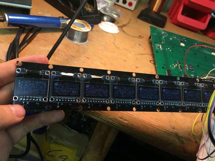
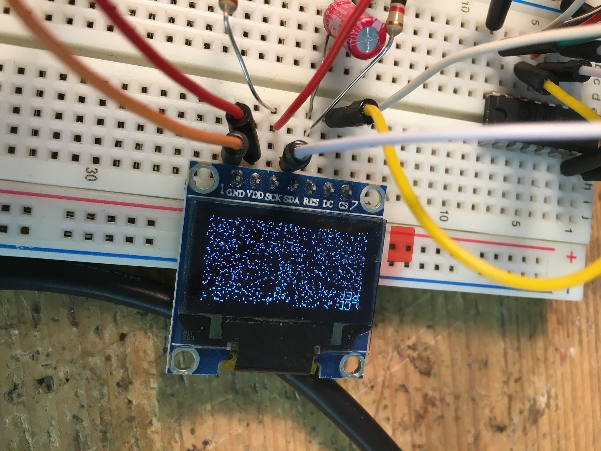
Hey people,
I need you experienced guys! I've made a mios32-Core by myself which I test at the moment. While the first one works great. The second one causes trouble. And I don't know why.
Please see the picture attached. Does anyone have an idea where the noise on the displays come from? I used this OLED-breakout (it contains OLEDs, Reset-circuits (Cap & Res) & Shiftregister) in some other projects already and it worked fine. So I assume the mistake is somewhere on the core. But as I said: Another identical core runs fine... Could it be the STM that is damaged?
To be sure, that the mistake is not on the 9x OLED Breakout, I also tried it with an OLED with Reset and shiftregister on the breadboard. Same here...
I now searched for about eight hours and also searched with an oscilloscope, but I was not able to locate the problem.
Thank you very much!
Best,
Chris

Help needed for implementing 3rd shift register for keyboard scanning
in MIDIbox NG
Posted
Hey people,
here is the problem:
FATAR has changed the diode-matrix of their keybeds recently. So the DIO-matrix is not usable for those keybeds anymore. I want to get it running and of course I'm happy to design a new DIO-matrix and of course post it here so everybody can use it.
So... I'm not 100% sure about the diode-matrix yet. In the old diode-matrix both keyboard sides (left and right) had separate rows. So the left side had 8 rows, the right side had 8 rows:
Look at this pictures. With "rows" I mean T0-T7.
In the new diode-matrix it looks like both sides use the same rows. Because if I plug in a new keybed (via an adapter) into a DIO-matrix (which I did many times before with old keybeds though old diode-matrix) it outputs correct values from a-1 (lowest key) till middle-C. With the next key C#3 the left side starts. But C#3 outputs a-1. Further tests confirmed my assumption, that both sides share the same set of T0-T7.
So that means: I need a shiftregister more than is available on the DIO-matrix. At the moment I have T0-T7 connected to the 8 inputs of the HC165, MK&BK are connected to the 16 outputs of the two HC595s. So in total I can connect 64 keys to the DIO-matrix. I now want to add another 595 to connect the last keys. Of course connecting the 595 itself is easy and done quickly. But I need to adapt the code and what I've tried so far was not working. I need to add a dout_sr3 to the code...
Any help?? Maybe @TK. could point me in the right direction!
Thanks people!
Best,
Chris