Sauraen
-
Posts
460 -
Joined
-
Last visited
-
Days Won
26


Sauraen's Achievements
MIDIbox Tweaker (3/4)
38
Reputation
-
I'm sorry about the delay, I'm not really active here anymore. The code is in /trunk/apps/synthesizers/midibox_fm_v2_1 and /trunk/modules/opl3. You should be able to use the opl3 module even if you want to write a completely new application layer. I never properly documented MIDIbox FM V2.1 for others to build it. However, there is some information in these folders, including the pinout for connection to the core mentioned in Readme.txt and defined in opl3.h. Other than the OPL3 module, the rest of MIDIbox FM V2.1 is a MIDIbox NG compliant control surface and standard MIDI I/O modules.
-
Glad to hear of your interest! The front panel is definitely a big hurdle. I have two versions of this project for those who want to do something but not build the front panel: MIDIbox VGM Player and MIDIbox Genesis Tracker. However, it sounds like these two might not have the functionality you're looking for. There is no version which provides the complete synth engine and all the capabilities but not the whole front panel. The controls exist to edit things and give the user feedback about them--having all of this stuff editable from menus would not only make it very difficult to use, but would require a lot of changes to the interface software. It's not too much of a stretch to say that the synth exists primarily to be a set of nice front panel controls for messing with the Genesis chips. In retrospect I understand that this made a high barrier to entry, but this is the box I wanted to build. The aluminum is a major cost, but it is not strictly necessary--since the whole front panel is on one large PCB, you can just use that as the front panel, though it's not as nice. If you would like to go this route I can gather interest and have another round of front panel PCBs manufactured, and sell you one for a reasonable price (under $100). There would be about 10-15 hours of soldering things (like the 638 LEDs) onto it, but that's all pretty straightforward. (And since you would not be using LEDs which have to be ultra-bright to shine through the translucent plastic, you could use cheap LEDs for all of them.) All that's left after that are the Genesis modules (which should still be for sale on the MIDIbox Shop--let me know if they're out) and the core, all of which are not very expensive or time-consuming. If you don't want to do this, I would suggest you build MIDIbox Genesis Tracker and control the synth from your computer. I had a working build of this firmware at one point, but I've since made lots of changes to the VGM module API and not updated this project, so it won't work as is--but if you want to do this I would be happy to get the code working again for you.
-
I never did extensive research of this--I designed the circuit that I thought was best, built it, it worked, and I moved on. I'm not surprised there's differences. I'd suggest you try bypassing the voltage divider on the sammichFM and see what happens. Clipping won't break things. It should be pretty obvious if things are clipping--play sine waves on every channel at max volume, and see if the output sounds distorted (not sine waves). The two op-amps you listed look pretty similar to me at a glance.
-
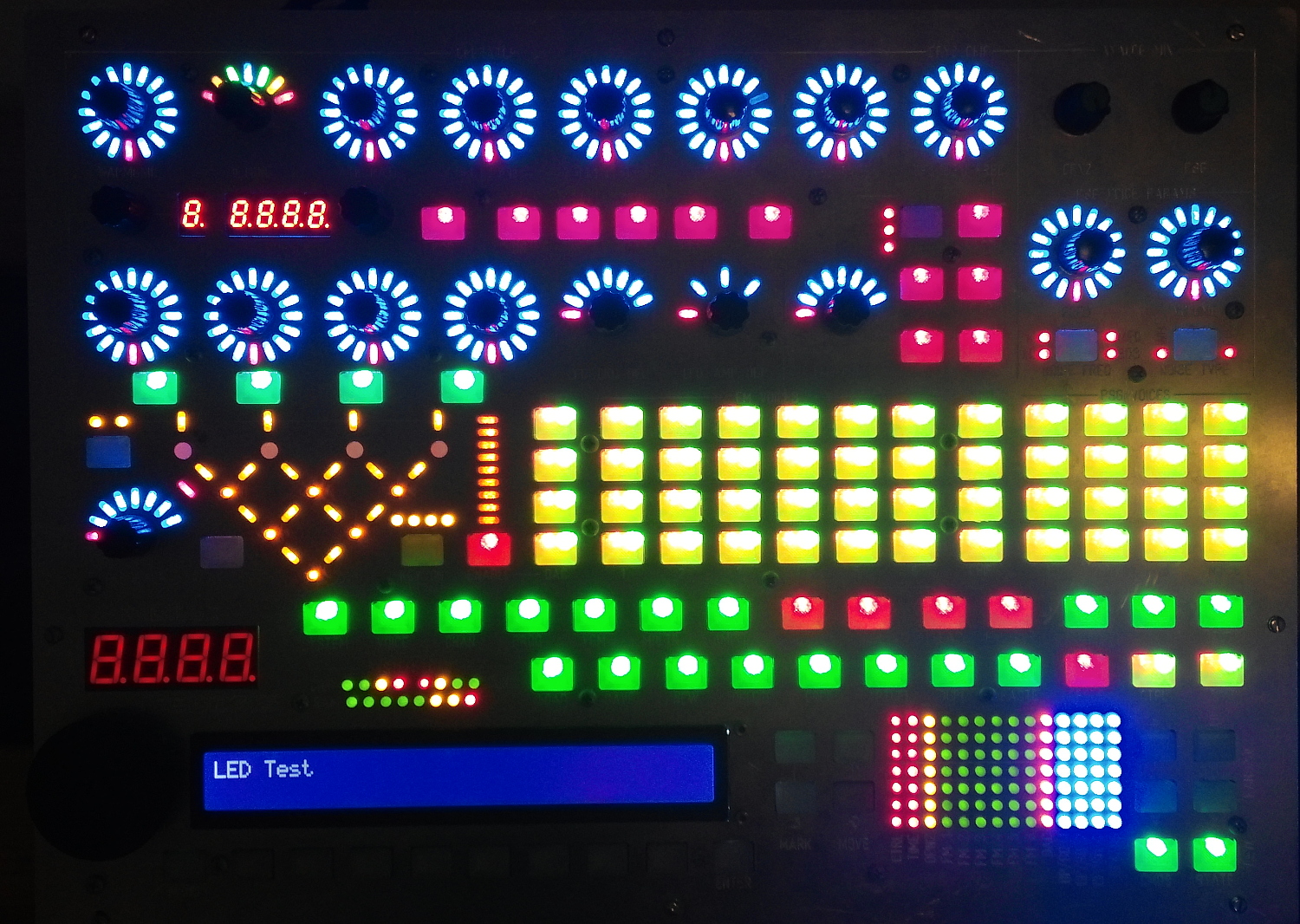
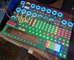
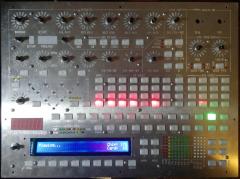
For the bicolor LEDs, what happened on the first build was that I accidentally got the wrong ones (common cathode instead of common anode), and since I didn't have time to get new ones in before I had to deliver it, I just put in discrete red/green LEDs under the panel, sort of visible through the hole. For my second build, the one I currently have, I got the right LEDs (the ones whose part number I listed there) and they work fine. The Triforce parts are a joke--there's no component corresponding to them, just the silkscreen graphic. They're labeled as "Red, Green, and Blue" for the Triforce of Power, Courage, and Wisdom. Maybe I should have labeled them all "Gold" instead. I just counted the actual LEDs of each color/category on my own synth in LED Test mode, and I get a total of 549. The differences from the list on the wiki are that I have 18 Yellow LEDs for lighting buttons/caps (instead of 24), and 76 Green LEDs for lighting buttons/caps (instead of 74). The numbers on the wiki were from my planning documents, but I don't remember in detail why they're different from the final version. I'm putting up a picture of my front panel with all the LEDs on so you can compare (or count if you really want). (I'm not counting the LED display segments, just the categories in the screenshot you posted.) Of course, when buying components, you always want to buy at least ~10% extra of each kind.

-
I would either go with the first, as that's what I did, or make them all the same color. The software will illuminate the 0 LED (lowest one) whenever the encoder is "active", i.e. there's a value being shown on it. Or, of course, show a value with other LEDs lit. But the point is, if there's no value being shown, all the LEDs will be off, so you can distinguish "zero" from "none". That's why I made that LED a different color, but there's not much need for it. I don't like the other schemes, they imply there's a difference between the other LEDs, when there isn't. Also @Smithy the most recent build of the code and the project file are up. One feature that I've been meaning to add, and maybe I can sooner or later, is a self-test mode for the Genesis boards where it automatically figures out which ones you have installed and what their clock speeds are. This will be helpful for you debugging the hardware, since the software you get with this project is a lot higher level than that.
-
It looks cool, and thanks for spending so much time on a project that isn't even yours! I like the idea of having the PCBs and back panel stuff mounted to sheet aluminum. But I think the most important thing is that whatever case "gets designed", if that's even necessary for the community, is something that future people can build themselves with minimal effort. I don't think trying to hide screws is very important. I think what's most important right now is that Smithy and the handful of other people who have purchased front panel boards from me can get their hands on a case relatively quickly and cheaply. When creating this project, I wasn't really expecting other people to build it just like mine--I wanted to give them the resources that I had developed, but let them do stuff like the case and I/O themselves based on general MIDIbox knowledge. For instance, I would give you the dimensions and layout of the back panel, but there's no reason other people need to make it the same way I did. Just one nitpick about your design, there is already a "MIDIbox Quad Genesis" logo, you can extract the vector art for it from the front panel layout file. Open the file in Front Panel Express and save as SVG, and then open it in Inkscape or your preferred vector editing software and get rid of everything but that text.
-
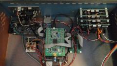
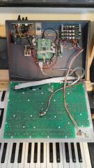
Trying to hit all the questions above: I use metric all the time except when the parts I'm using are themselves measured in English system (e.g. 1/4" spacer or 0.1" DIP spacing). I try to convert for people. (proceeds to not convert below...) The Genesis module sandwich should be mountable from the bottom rather than from the back, its width is about the same as its height. The Genesis modules were designed to be stacked like that--you will need a lot of cables otherwise, and some parts like the mixing circuit will be more of a pain. The reason the spaces are inconsistent is as follows. The wider spacer is a 0.75" threaded aluminum spacer. The top three boards screw into it from one side, and the bottom board and the case screws in from the other side. I didn't have screws long enough to go through all four. The other spaces are 2x 1/4" for a total of 1/2". As long as you have about that much clearance between all the boards, the spacing doesn't matter. The headers are long pin sockets for Arduino shields, added the info to the wiki. The particular part looks like it's obsolete on Mouser, but once you see it you should be able to get something similar. They'll be longer than you need, clip the ends of the pins to fit.
-
The aluminum front panel is 15" x 11" (38.1 x 28 cm). The dimensions of the rectangle around the border where the screw holes are is about 36.8 x x 26.4 cm. The case is 10.5" (26.7 cm) from back to front, 10.8 cm tall in the back, and 3.8 cm tall in the front. Everything fits reasonably well inside--there's some extra space, but especially in the front a lot of that is taken up by the front panel. The height in the back is just right for the stack of Genesis boards.
-
-
-
The cases are from Cadet electronics trainers from the late '80s which I dumpster-dived a few years ago. (The more modern ones have plastic cases and are somewhat smaller.) I actually have one case left, but it might not be worth it to ship, as it's heavy steel. I might recommend you just build something out of wood or whatever. Any clean 5V power supply should be fine, just be aware that the front panel can theoretically draw up to 1.2 amps (if it turns on all the LEDs at the same time and then crashes so the matrix isn't being updated). Under normal use it's much less than that, probably about 300 mA. The supply you mentioned should probably be fine. The source code is at http://svnmios.midibox.org/listing.php?repname=svn.mios32&path=%2Ftrunk%2Fapps%2Fsynthesizers%2Fmidibox_quad_genesis%2F ; it hasn't been updated in a while, but when I get home (I'm away right now) I'll put up the latest version. I never put up the hex file, I was expecting everyone to compile it from source, but I guess that's dumb and I should put up the hex file too. There's more features done, including an automatic velocity sensitivity thing--but still saving isn't finished, oh well. :)
-
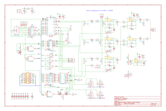
@Smithy: yes, you found a mistake. R14 is DNP. I updated the page, and also fixed another minor mistake I noticed. When you're talking about "enclosure for the Front Panel", do you mean an aluminum or plastic panel for the front panel PCB to mount under, or do you mean an enclosure for the synth?
-
^ Correct.
-
Summer break has begun and I have a little time to work on the project. I've been continuing some unfinished bits of the software, but it's relatively close to a complete, workable beta build. I would like to check in with those who have bought front panel boards to find out how their assembly has been going. Ideally, I'd like someone to get the hardware done and then give me feedback on the software, so I know what is most important for me to spend time on.
-
For the buttons on my old project MIDIbox ASIDITY and on MIDIbox FM V2.1, I had the buttons printed by someone from the RepRap forums (the particular individual is no longer doing printing for people online). In both cases the order was about $20-$30 plus shipping. As stated on the wiki, if someone is trying to charge you noticeably more than this (e.g. $1 per piece), either they have the scale of the STL files wrong and think the parts are gigantic, or they're ripping you off. (For MIDIbox Quad Genesis itself, I had a friend do it, with the deal that I bought him a roll of the transparent plastic I wanted and he kept the extra, in exchange for free machine time.)
-
You and one other person are definite "Yes", and there's another person who I think lives in Europe who is interested but not quite ready to invest in a new synth project. The PCBs are already made, I got 10 made when I originally built the two synths. So the extras have been sitting on my shelf for a year. I really just want to make back what I invested in them--and of course help some other people get synths. :) I will pester SmashTV about shipping to Europe again and see what happens.