

Sauraen
-
Posts
460 -
Joined
-
Last visited
-
Days Won
26
Content Type
Profiles
Forums
Blogs
Gallery
Everything posted by Sauraen
-
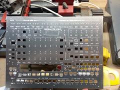
R2-3 and C7-14 are for the YAC512s, I would leave them alone. C15-22 are power filtering capacitors, as I said I would replace those ones that were originally to the -12V rail (i.e. C17, C18, C21, C22, C25, C26) with jumpers (because they would be between two different wires that are both supposed to be ground), but leave the others alone. That might actually be a good idea, it should reduce the noise at least a bit. But that will only work if you're powering the synth originally from something higher than +5V; what were you going to use? (Hopefully not your computer's USB port--that'll be noisy enough to ruin your audio from the start! Oh wait, you're using the old 8-bit core, you don't have USB...) Probably very noisy, but why don't you buy one and test it out? :P
-
Hi TK, This is two independent issues I'm having, but there may be a single solution for the two of them. The first is that when I was designing the LED displays for my front panel, I misinterpreted the config file for the 7-segment displays example (code and diagram) and thought the "sel" DOUT shift register was connected to segments a-g, and the "r" (which evidently stands for "red", not "row") shift register to select which digit. So that's how I wired it, and obviously I'm getting all messed-up characters on the displays. It doesn't look like there would be an easy, existing software solution to this, but maybe there could be some way to swap the handling of rows and columns when writing to the LED matrix driving the digits. The second is that the way I have the buttons connected, I use "sel" wires as a lower-level than "r"/"din" wires--that is, for instance, softkeys 1-8 are all hooked to a single DIN pin but each to the eight different DOUT selection drivers. When I use button_id_emu_offset or led_id_emu_offset to convert them into individual button or LED handlers, those softkeys appear as buttons 1001, 1009, 1017, 1025, etc. instead of 1001, 1002, 1003, 1004, etc., because it's going through all the "r"/"din" wires for one "sel" wire first and then moving to the next "sel" wire (which makes sense on a hardware level). I know this is not a major deal and just means that my config files will not have all the buttons in a nice neat order, but again if there was some optional way to reverse the handling of rows and columns, it would make this easier. I'm thinking something like a "swap_rows_columns=<1|0>" parameter for DOUT_MATRIX and DIN_MATRIX definitions that would work like this. The hardware would still be configured as the sr_dout_sel* and sr_din* and sr_rgb statements in the definition suggested, this new parameter would not change that at all. However, if it was 1, any time any function wrote to (DOUT) or read from (DIN) an element in the matrix, the row and column indices given would be swapped before reading/writing. Might this be easy to add? If you want me to try adding it myself, I can try, I've already been fooling with adding a "type=MBFM MBFM=...", but other users might also be able to benefit from this ability to swap rows and columns. Thanks, Sauraen
-
-
It should absolutely be possible. My concern was not going to a single +5V rail, but using +/- 5V instead of +/- 12V, so I used a more complex setup than below. The op-amp MCP6004 is rail-to-rail at 5V, is suitable for audio applications, and is pin-compatible to TL074 (I used MCP6004 for IC3 and IC5 but TL074 for IC6, and inserted biasing circuits between the two amplifier stages, because I wanted to convert between +5V and +/- 5V). So I would recommend you replace all the TL074s with MCP6004s. But then the one problem I can see is that the circuit around IC6 will no longer work--both because it's a non-inverting amplifier configuration referenced to ground (while your audio signal is biased to +2.5V), and it has a gain x2 which (if the input signal is rail-to-rail) will make it clip horribly. So you have a couple options: make it a unity-gain non-inverting amplifier by replacing R5 and R6 with jumpers and leaving out R4 and C27 (and the corresponding components on the other three channels, look at the schematic); or you could leave out the second stage of buffering altogether, leave out IC6, replace R5 with a jumper, leave out R4, R6, C27, and short IC6 pins 1 and 3 (and the corresponding spots on the other three channels). As far as power, connect +12 to +5, GND to GND, and -12 to GND; and replace all the capacitors between the -12V rail and GND with jumpers. I will guarantee that the MCP6004 will work, in so far as I used it in my build and it works fine; but I will not guarantee that the modifications to the IC6 circuit will work. Buy a couple extra MCP6004s in case. :) (Though none of this should fry the OPL3 or YAC512s, since they're powered from the separate +5V supply, as long as you have that hooked up with the polarity correct, heh heh!)
-
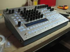
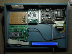
MIDIbox FM V2.0 Prototype - Front panel inside complete
Sauraen posted a gallery image in MIDIbox Gallery
From the album: MIDIbox FM V2.0 Prototype
That took like 50 hours. If it looks like a brain that's because IT IS!! "SENTIENCE LEVEL 1 ACQUIRED... I REQUIRE FIRMWARE!" -
From the album: MIDIbox FM V2.0 Prototype
Why are those knobs so ugly? Relatedly, does anyone have 40 nice-looking knobs they want to trade for these ugly ones? :smile: -
From the album: MIDIbox FM V2.0 Prototype
-
From the album: MIDIbox FM V2.0 Prototype
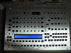
I made a serious error in the process of infilling, but with the light at this angle you can't tell. :smile: -
Although I've been recently working a lot on MIDIbox FM V2.0, I demoed ASIDITY for an electrical engineering class and hence did some work on it. I've gotten the three CPUs to cooperate via MBNET, and have front panel control changes going to the SID core as well as track changes from MIDI messages from the SEQ core. And I wrote another test program (well, two programs, one for SEQ and one for SID cores) that give me control of most of the OPL3 parameters via the front panel. So ASIDITY makes a quick appearance at the end of this video:
-
See an LPC17 core controlling two OPL3 modules and obtaining up to 36-voice polyphony (with the same dumb demo organ patch from ASIDITY that's hard-coded into the OPL3 driver as the startup default):
-
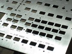
Isn't it nice to have friends who have CNC mills? :D
-
From the album: MIDIbox FM V2.0 Prototype
Isn't it nice to have friends with CNC mills? :D -
Sounds good! What did the other beach-goers think of the drone?
-

From the album: MIDIbox FM V2.0 Prototype
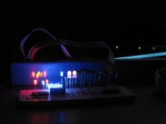
Stress-testing the +5V rail of the PSU. This little breadboard draws 500 mA. The room isn't really that dark, though the lights are off; I just had to turn the brightness on the camera down all the way. :smile: -
From the album: MIDIbox FM V2.0 Prototype
Stress-testing the +5V rail of the PSU. This little breadboard draws 500 mA. -
From the album: MIDIbox FM V2.0 Prototype
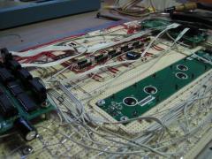
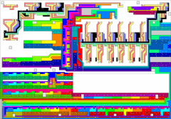
I have a friend with a CNC mill who's willing to mill the front panel and front panel board for me at cost (i.e. I provide the aluminum, copper clad board, and pay him for the bits he goes through milling the copper clad board, heh heh). But I don't have a program that will let me design a circuit board for milling like this--so I did it in Front Panel Designer! I put the image into an image-editing program and filled each of the "traces" with a different color according to their function, mostly to check for mistakes, and partly to help when writing the MBNG config files. But it also looks cool! -
I'm pretty sure I just went to transistor arrays, filtered by quantity = 8, ordered them by price, and picked the cheapest one that was in stock. According to my BOM spreadsheet it was $0.81 (~0.59 euro). But I don't think it matters which kind of sink drivers very much, I used a bunch of discrete MOSFETs in TO220 packages bolted to a heatsink in my ASIDITY project, and it works fine--but that was because there were around 750 LEDs in the matrix!
-
Thanks! I am using dedicated sink drivers, a Darlington array (Mouser 757-TD62083APGON), hence the inverted_sel=1. :) Thanks for having the DOUT boards support these too!
-
Hi TK, Is it supported to have a single shift register provide the row selection signals for multiple matrices that have the same number of rows and the same inverted_sel mode? From another thread, it looks like this is possible, but I just wanted to make sure before having a PCB milled! For example: DOUT_MATRIX n=1 rows=8 sr_dout_sel1=1 inverted_sel=1 sr_dout_r1=2 inverted_row=0 mirrored_row=0 DOUT_MATRIX n=2 rows=8 sr_dout_sel1=1 inverted_sel=1 sr_dout_r1=3 sr_dout_r2=4 inverted_row=0 mirrored_row=0 DIN_MATRIX n=3 rows=8 sr_dout_sel1=1 inverted_sel=1 sr_din1=1 sr_din2=2 inverted_row=0 mirrored_row=0 Thanks, Sauraen
-
-
From the album: MIDIbox FM V2.0 Prototype
-
PCB grounding with mixed signals chips, talks about crosstalk.
Sauraen replied to Antichambre's topic in Tips & Tricks
That first tutorial PDF was actually really helpful! I've designed one set of mixed-signal boards, that for my ASIDITY project, to hold two SIDs (which are mixed-signal chips, of course) and a custom digitally-controlled feedback circuit. I was not able to determine whether there was significant noise getting from the digital signals to the analog side, because I always had my computer hooked up to the synth via USB, which connected the ground to that of my computer. My computer has a very noisy switching power supply, so the noise from that overpowered any noise from the SIDFB boards. Speaking of my computer, my new computer has some sort of severe crosstalk issue: any sound coming out of any audio output jack, whether sharing a ground or not (e.g. headphones), is corrupted by an incredible amount of noise, as loud as the audio it's playing. It sounds like a data bus to the hard drive! So I've had to hook up my computer to my mixer via SPDIF/TOSlink optical and then have a converter to analog powered by a linear power supply that only shares a ground with the mixer. The ground is completely decoupled from that of the computer. Still working on how to record audio into the computer, currently working on a USB isolator that would allow data to flow between the computer and a cheap USB audio interface while keeping their grounds separated. -
For the benefit of those who do not currently have a completed MBFM V1.4, could you post some demo sounds/songs?
-
It's going to be a couple weeks before I will be able to test this (my front panel is still raw aluminum and copper clad board), but once I build it I should be using each valid combination. But can't you just take a controller you already have, swap each pin statement in the configuration file (e.g. change 0:1 to 1:0) and see if all the encoders turn backwards? Edit: Working fine, thanks very much! Encoder rotates backwards with pins in wrong configuration, then switching them and saving causes it to rotate correctly again.
-
Thanks! Demosong is not going to happen for a while, though. Finished OPL3 boards does not mean finished anything else (in this case, only also finished core board and power supply)! I'm waiting on some encoders from ebay to arrive from Asia, and I have a friend with a CNC machine who's willing to mill me a front panel and the circuit board for it. Hopefully when they come, the front panel will be all together in only a couple weeks! I don't know if anyone else here is on the east coast of the US, but I'm going to MAGfest and hope to have a version of this build to bring with me that's sufficiently working for me to jam with it. So that's sort of a deadline for this project.
