Phatline
-
Posts
1,285 -
Joined
-
Last visited
-
Days Won
72


Phatline's Achievements
MIDIbox Guru (4/4)
124
Reputation
-

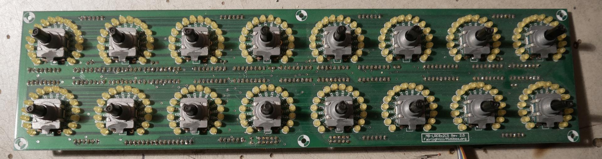
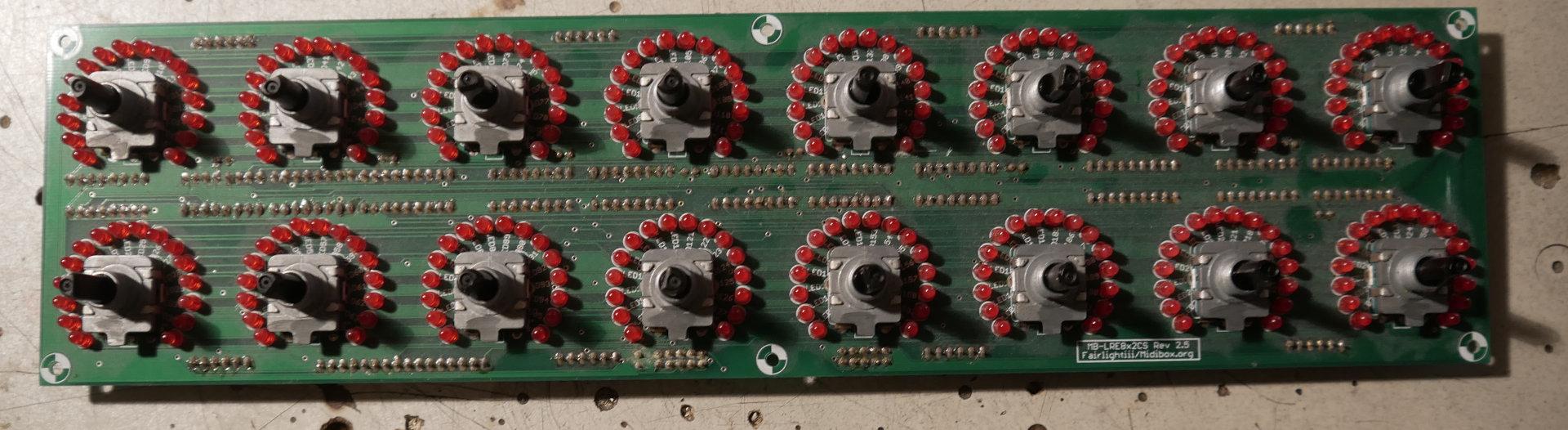
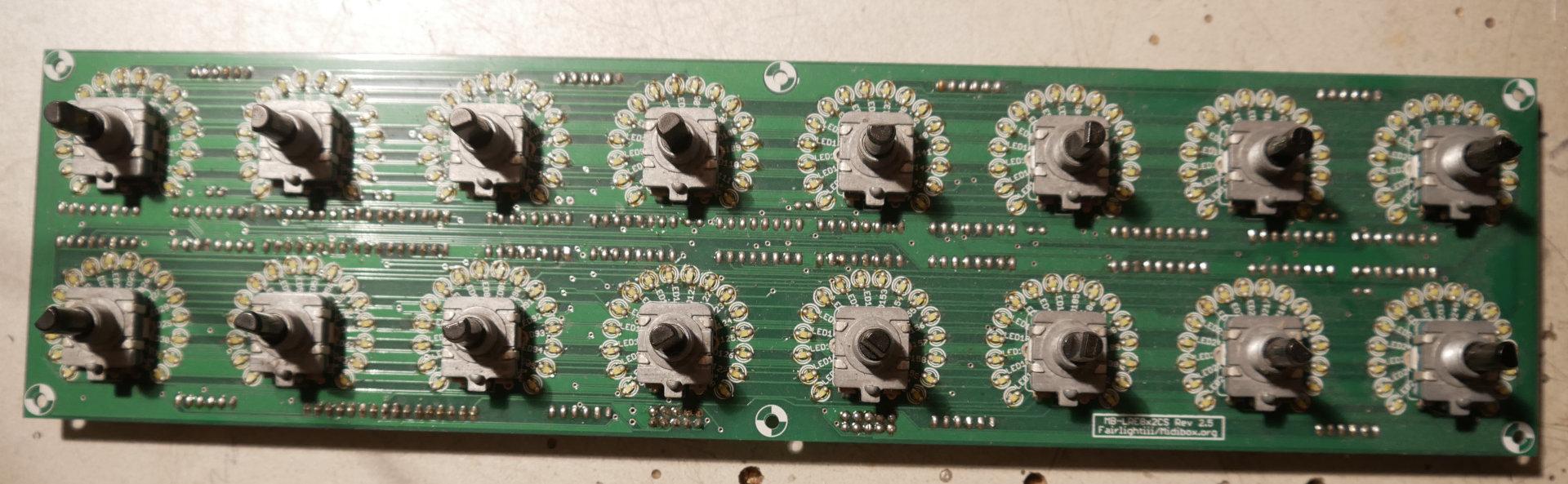
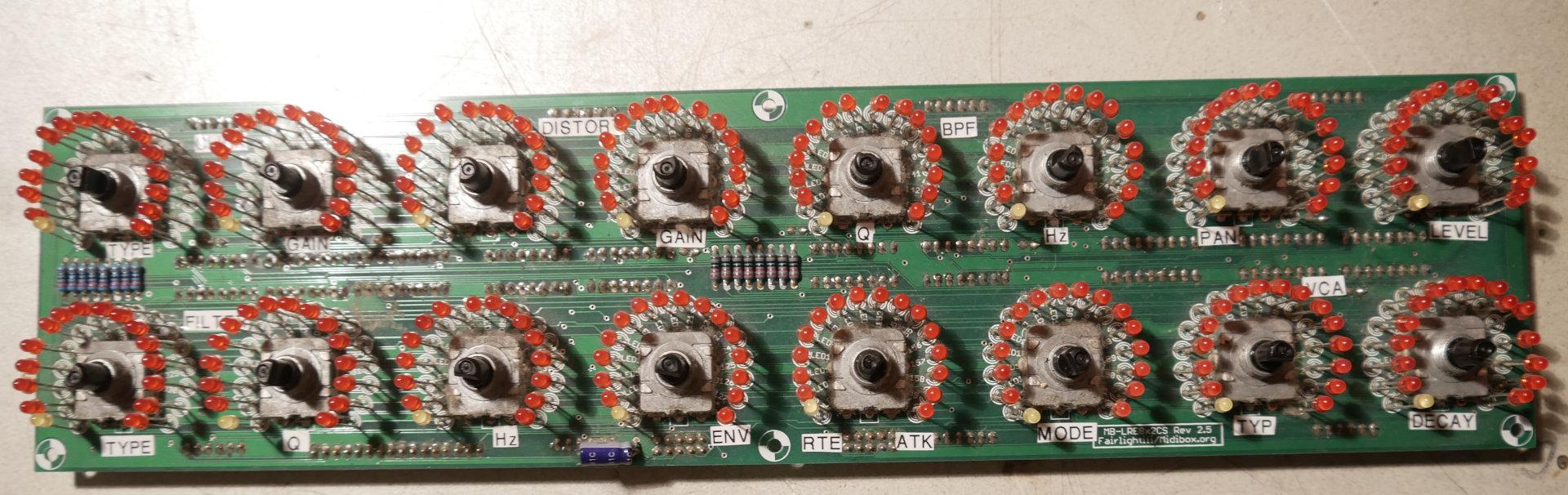
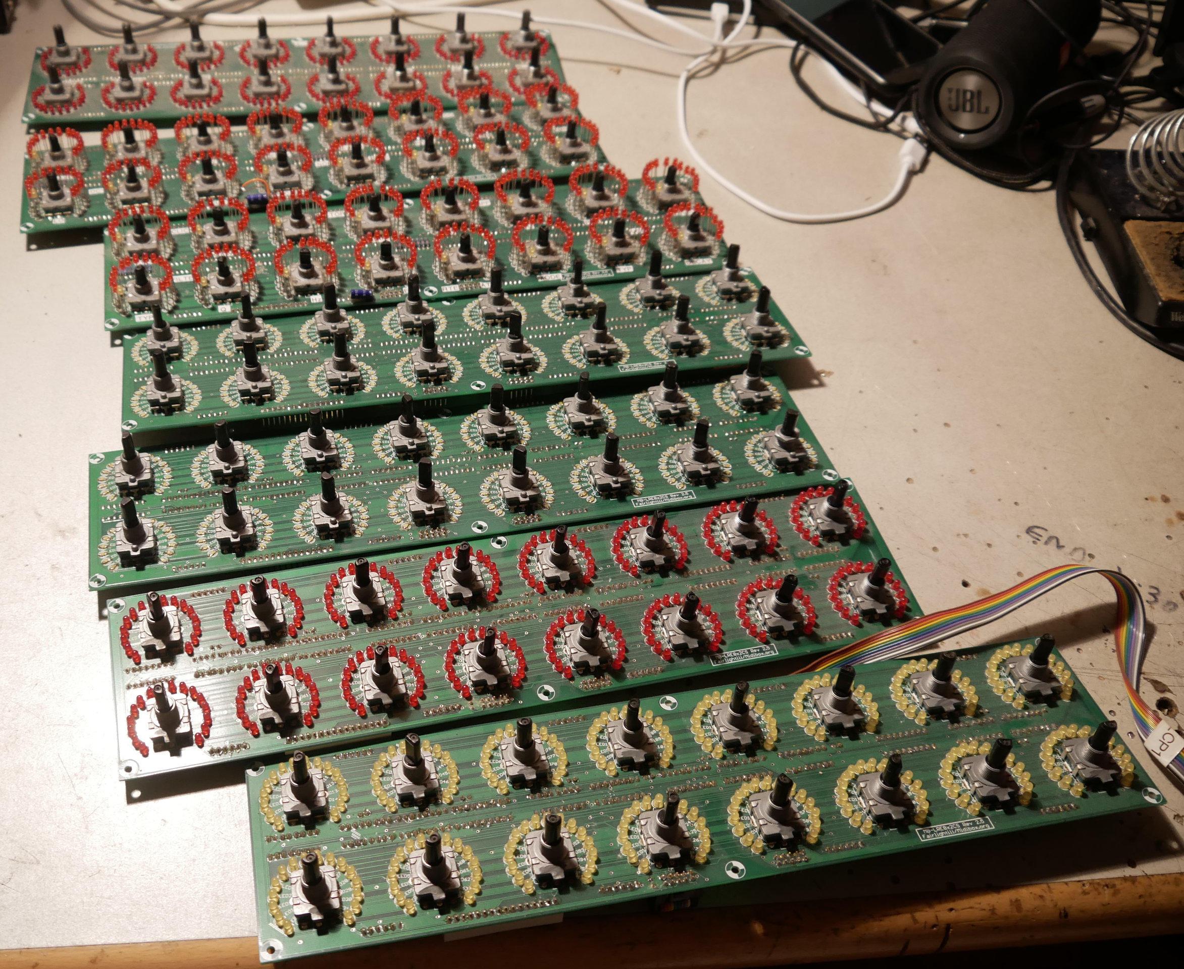
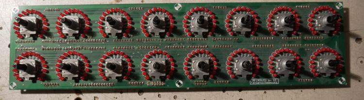
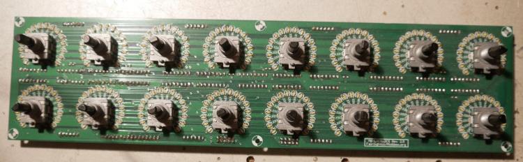
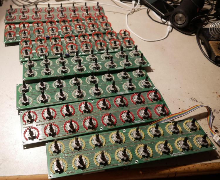
[S] 7x MB-LRE8x2 CS Rev 2.5 (fully stuffed with parts)
Phatline replied to Phatline's topic in Fleamarket
the rest off them are now sold to @wlinart can be closed - thx. -
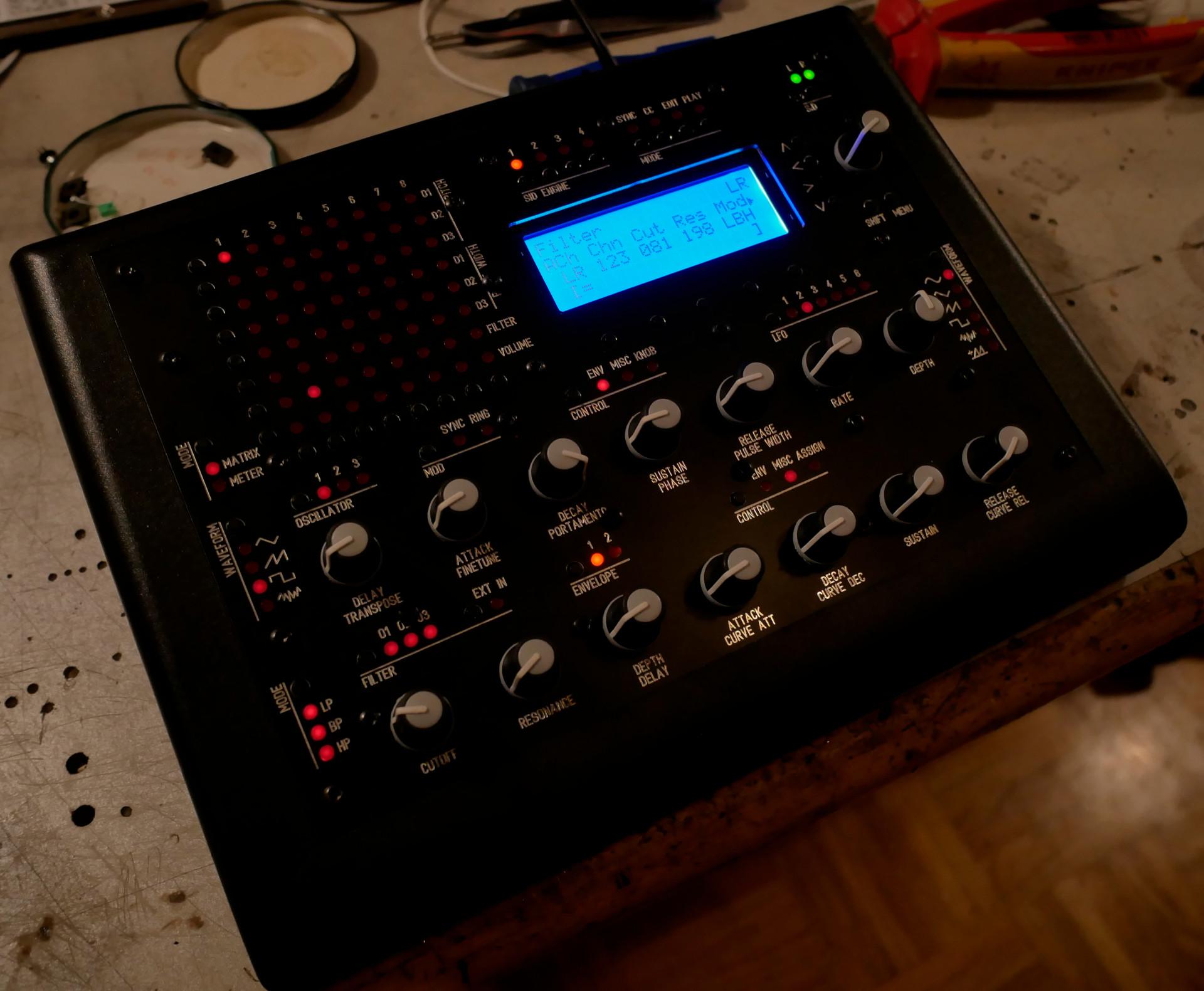
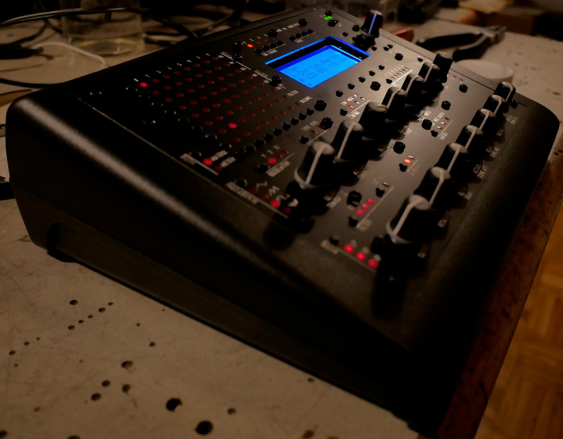
MB6582 passive cooled (purple and green SCREEN/LEDs)
Phatline replied to Phatline's topic in MIDIbox SID
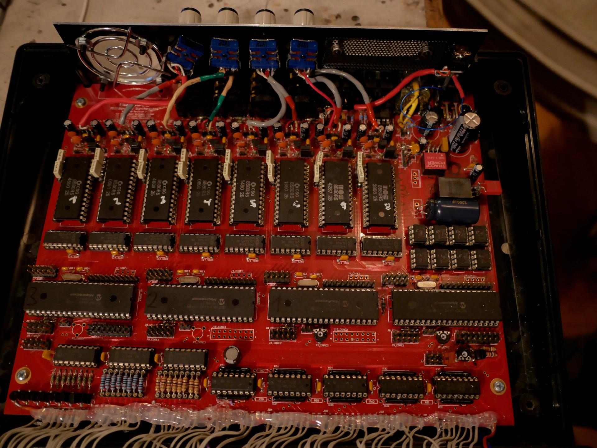
the 7th sid (counted from left) the Denoise Cap is connected false.... the rest are correct.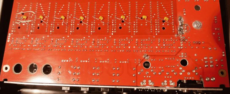
-
MB6582 passive cooled (purple and green SCREEN/LEDs)
Phatline replied to Phatline's topic in MIDIbox SID
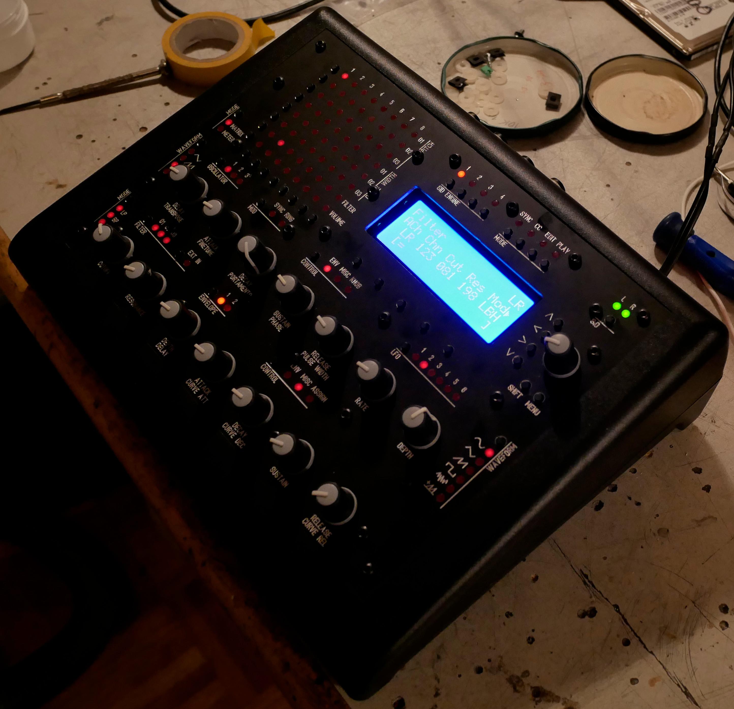
a nother passive SID alive...


-
new price 450€
-
USB host doesn't work but i follow the TK topic
Phatline replied to xarolium's topic in Testing/Troubleshooting
you sayd you made a custom USB OTG cable... you think you have done it right (ID PIN ??? )? if you have done right, maybe you have wrong bootloader settings: (http://www.ucapps.de/mios32_bootstrap_newbies.html ) -
USB host doesn't work but i follow the TK topic
Phatline replied to xarolium's topic in Testing/Troubleshooting
done this? #undef MIOS32_DONT_USE_USB_HOST ? no just remove the line.... -
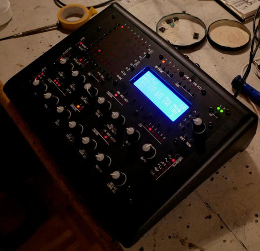
i programmed a max for live patch for it to move a 12x16 Grid launchbox, mute,arm,solo,stop... plus a midiclip editor... which is work in progress... http://wiki.midibox.org/doku.php?id=triggermatrix5#software
-
new price 650€
-
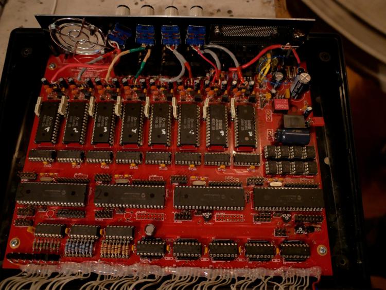
new price 750€ i combined and wrote the 32bit Code so it now can comunicate with a SEQV4+, and off course with the SEQV4 standard, here is the sourcecode + firmware: BLM_V01.7z see also this short video (german):
-
try: upload the newest bootloader (with mios studio + http://www.ucapps.de/mios32/mios32_bootloader_v1_018.zip), reboot, on mios-studio - go to the mios-terminal-section, and type "help", then change to LCD type, the number off characters (2x40) and the numbers off X and Y Screens you have on your sequencer... then type "store" (was it store...save...? no idea, all commands are listed when you type "help") the core reboots and you will see some Text on your screens - then you have prooved that this is no hardware issue, then upload the newest LPC17 Seq V4 firmware, then report if it is still Black Blocks you see. by the way is your "orginal old core setup"? has the LPC-core ever worked? if not, try to replace the HC595 chip on it (IC2), also check the solderpoints that have to do with the LCD-Section (see the shematic: http://www.ucapps.de/mbhp/mbhp_core_lpc17.pdf) ... Specially the groundpins, since we have a ground plane here, the plane sucks away the heat coming from the soldering iron, give enough heat on your solderstation, and heat the pins longer then normal... but bevore remove the lpc board, and IC2, so you dont destroy them... thats all - what comes in my mind.
-
ok - i wrote sauren. if i get feedback from him - that he have a pcb - then i ask you @Smithy again - if you still have a pcb-frontpanel then. - mike.
-
hei, what do you payed on jlpcb for one set (devidet)? is there a change to get a Sauren Frontpanel PCB anywhere? - i am interested - but not sure that i get all i need to build this (the FM-PCBs are sold out - as example: https://midiboxshop.bigcartel.com/product/midibox-quad-genesis-board)
-
maybe its the Ripple off the PSU about your PSU - reichelt specs is saying : "Ondulation résiduelle : 80 mVcàc" i guess this is not a 50Hz ripple but HF ripple... --- i guess some small cap (100nf, 10pF) and a big Cap (depends on the load, use for example a 100uF and a 2200uF) on the output off the PSU would reduce that "ripple"... * maybe that caps are not enough and you need some more filtering (coil, resistor, lpf...) but i would start with some caps... the connections in your 2nd picture are not necessery - i guess (dont seeing the whole picture, but i think so...) --- so picture 1 is correct. by the way - its only the last LED that flickers? maybe you have to terminate the DO line on the very last LED off the Chain with a 10K resistor to 5V or Ground. else it could be a software problem, when the software loops thru the LEDs, and when it comes to the last one it jumps to the beginning off the chain... try to programm in the ng code one more LED (which in reality not exists) - so you can be sure that this is not a software bug... - but dont ask me about ng-programming --- no glue about that. - mike.
-
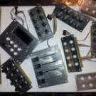
I sale them: 2x with wite SMD LEDS: (for Acrylic Panels without Thruhole) - these are the only two boards with ENCODERS with inbuilt pushbuttons 30€ the Pair SOLD to KSIR! 2x with RED 3mm LEDs - mounted flat to the pcb (for Acrylic Panels without Thruhole) 30€ the Pair 1x with Yellow 3mm LEDs - mounted flat to the pcb (for Acrylic Panels without Thruhole) 10€ 2x with RED 3mm LEDs for thruhole Mounting 20€ the pair I dont have Encoder-Nuts for them. Shipping only to the EU why i sell them? > i dont need them... if i am in need i would design my own pcb...


-
new price 800€ -serviced yesterday.