Phatline
-
Posts
1,285 -
Joined
-
Last visited
-
Days Won
72
Content Type
Profiles
Forums
Blogs
Gallery
Everything posted by Phatline
-
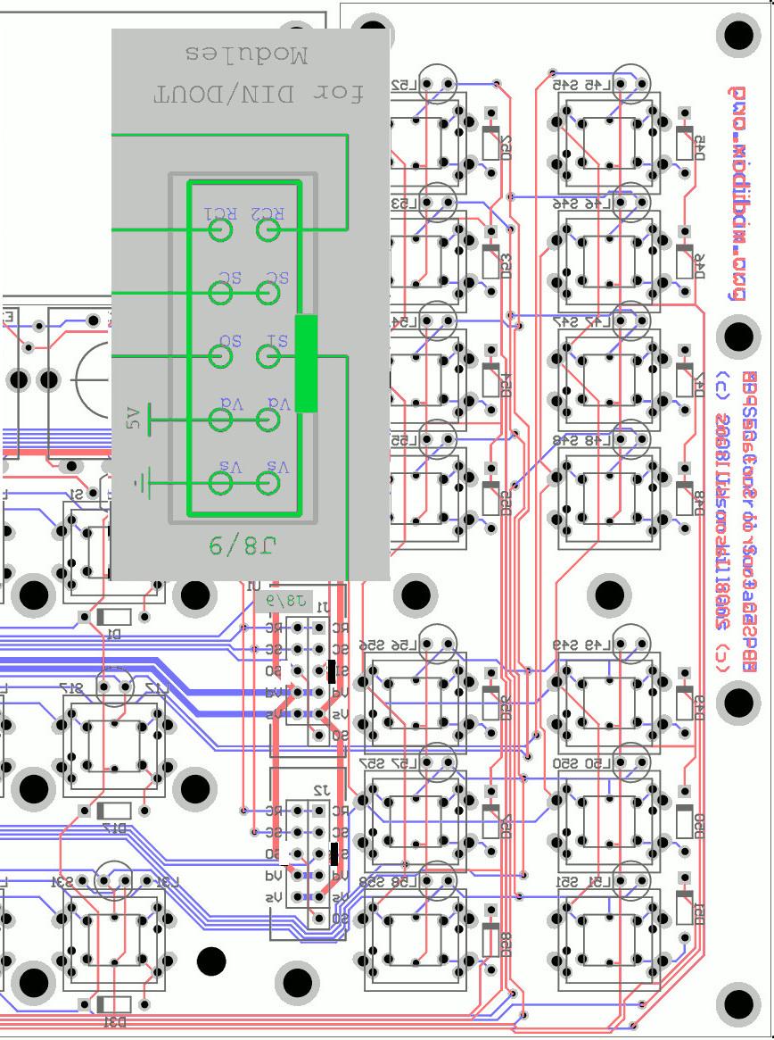
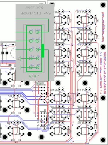
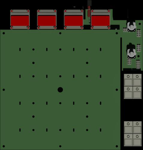
Aaarg, you are right, i forgot that its soldered on the backside... looking from the backside off the PCB the Nose should look to the right side see this mirrored Picture, with corrected Noses
-

Open PAD (aka akai MPD style PADs on MIOS)
Phatline replied to Phatline's topic in MIDIbox User Projects
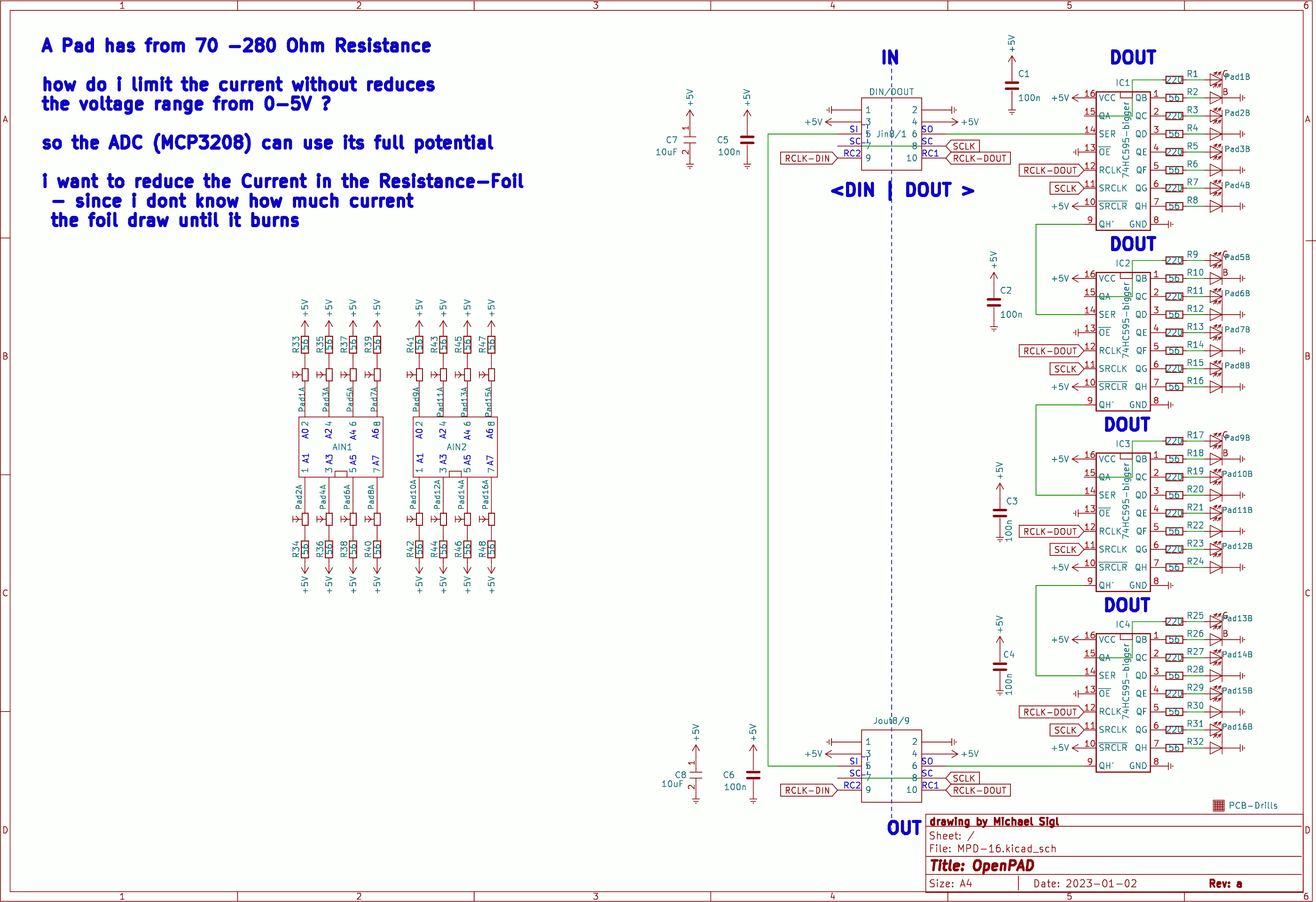
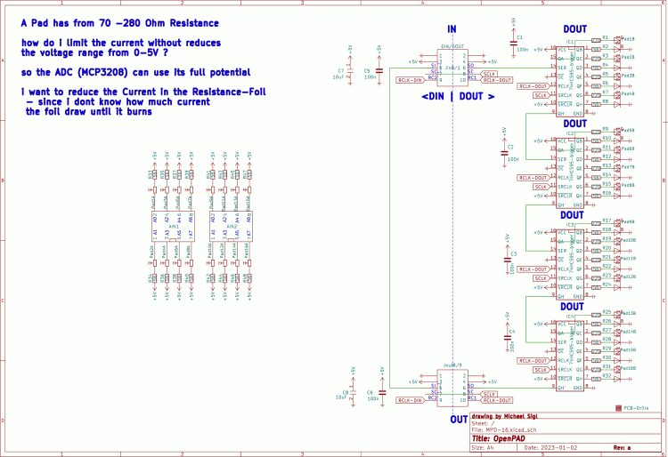
the quest still is: the akai Resistive Foil - has a resistance from 280 Ohm if you measure diagonal between the corners. Our MCP3208 wants 0-5V. How do i limit the current going thru the Foil, without reducing the 0-5V Range? OP-Amps? how? Thx 4 Input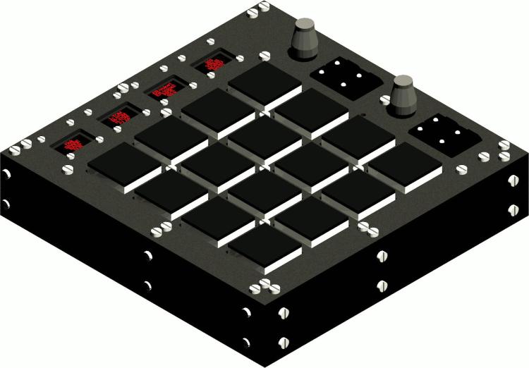
-
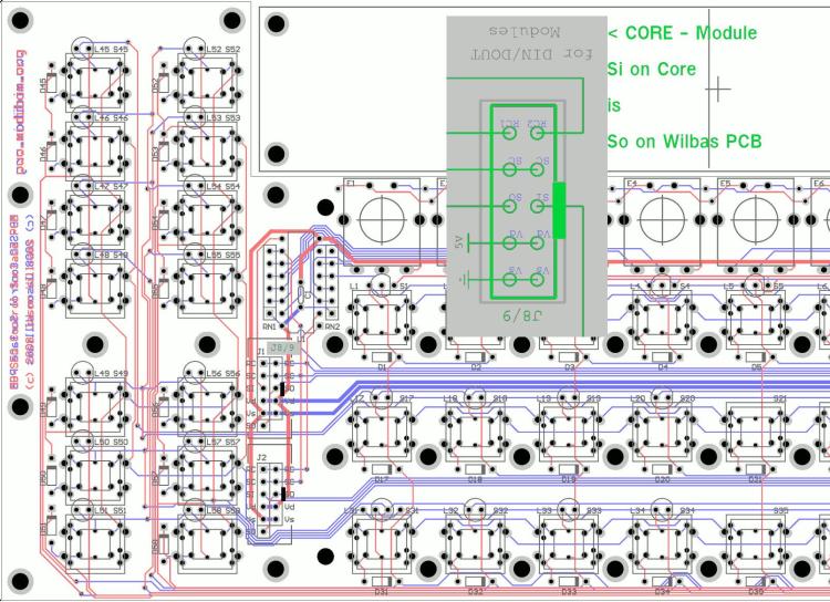
this should help (see the green) - I have drawn Rectangels for the Connectors/or Pfostenbuchseś NOSE (EDIT: this Picture is only right if the Cable is soldered on the Top side - which nobody does --- see 2 posts below this one for the correct picture from the backside) (PS the PCB is shown from TOP aka Component-Side) AND its a 1:1 Cable, Si is only otherwise Labeled > for example: the DOUT Pin "So" on the Core Module - is labeld "Si" on the Controllsourface the DIN Pin "Si" on the Core Module - is labeled "So" on the Controllsourface thats the logic behind most all Modules - for example the SD-Card-PCB has the same OUT<<>>IN Mirroring - but thats all only Labeling, the wiring is 1:1. >>> wilba had done drawn his Board that Si is Si and So goes to So So you just have to know how to crimp a Wire 1:1, and you are good. (PS2: your picture off the cable is so small i cant identify anything there...)
-
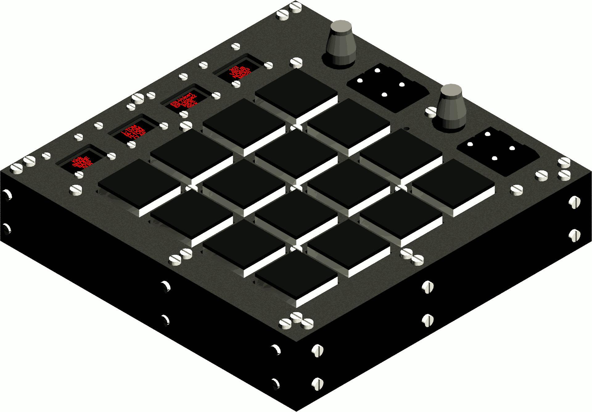
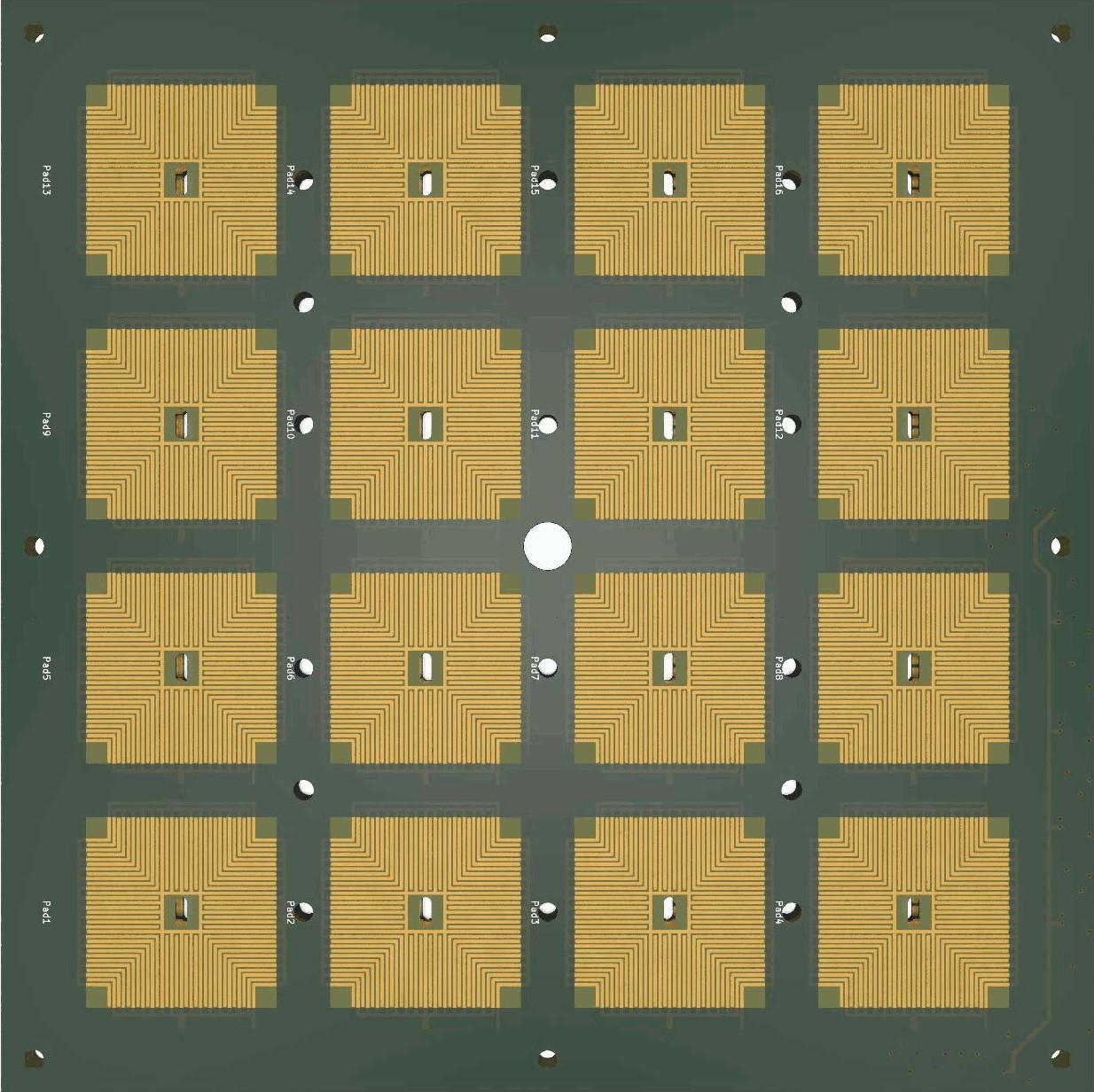
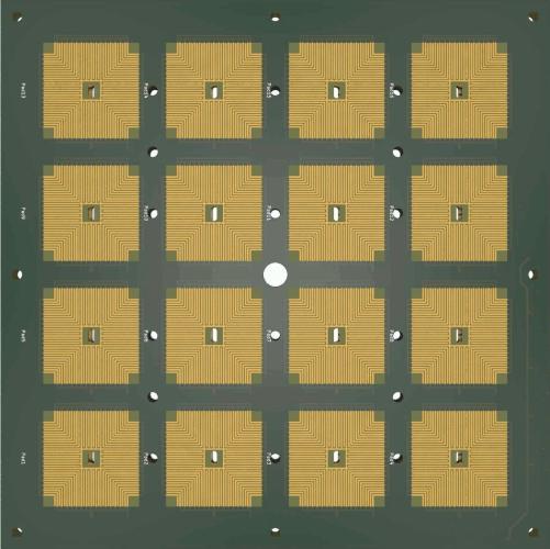
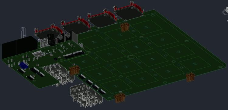
Hi, i recently buyed a Akai MPD226... i hoped i could use it standalone with MIDI-TRS/DIN Hardware... but LED Feedback doesnt work (aka Notes from a Hardware Sequencer give no Response to the PADS) - short the Akai Firmware sucks. I made a teardown, searched on the MPC-Stuff website... and made PAD-Footprints for KICAD, made shematic and so on: Result: OpenPAD I dont use the same shematic as Akai did... the multiplexed 4 Inputs of a STM32F103 with some HC595. My goal is to use 2x MCP3208 and connect them without switching to the PADs. SO I HAVE A QUESTION: the akai Resistive Foil - has a resistance from 280 Ohm if you measure diagonal between the corners. Our MCP3208 wants 0-5V. How do i limit the current going thru the Foil, without reducing the 0-5V Range? OP-Amps? how? Thx 4 Input I too have drawn a Core PCB 4 Pick and Place... incl STM32F407VGT6 ;)
-
dont know anything about MBNG-Script, nor with Cubase (except that i tryd it - and had the feel "its not my workflow, and i cant customize my workspace here") I had those Mackie MCUs and wrote a MaxMSP (standalone) Groovebox for it, that was 2012 - so the knowledge is anywhere in my brain.... http://wiki.midibox.org/doku.php?id=triggermatrix&s[]=triggermatrix about MCU since it uses sysex, sounds do-able, what that means in MBNG-Script - you will have to find out, if you ever come to a point where you see that MBNG-Script cant do what you want (i dont know) , you can call me to discuss for a more custom code.
-
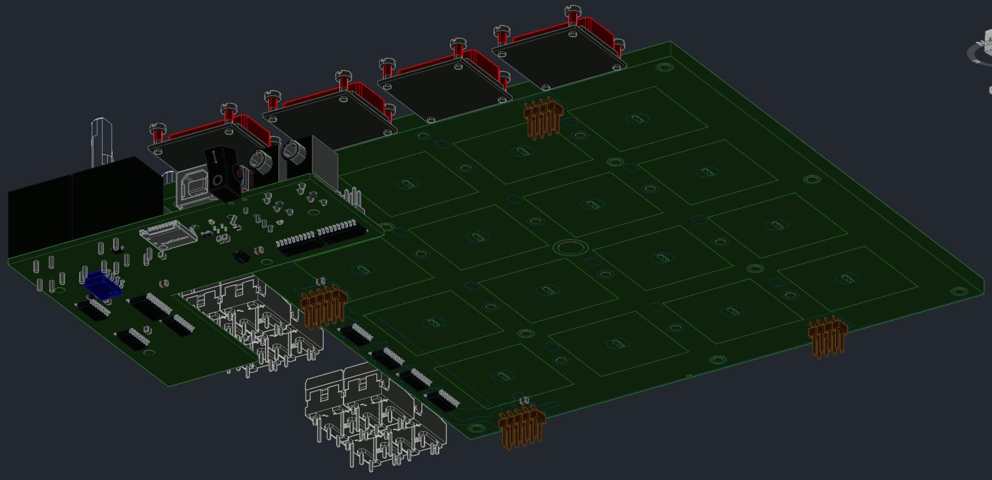
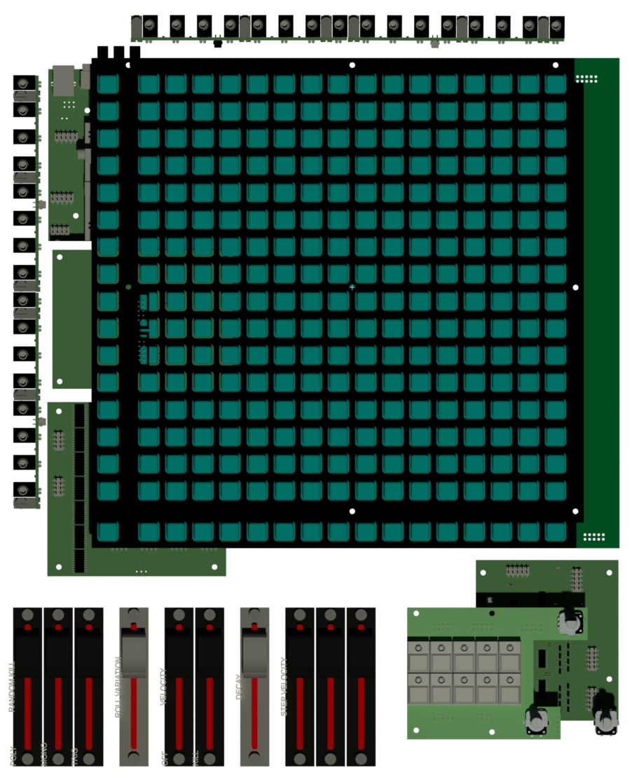
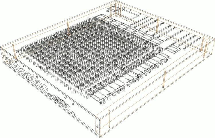
the next generation off Triggermatrix, with insights to shematic, the board-files i will not set free... the Pictures from the Boards are for debugging reasons only. where possible, i made pick and place ready boards - to reduce soldering time... at this point the big BLM16x16 board is not pick and place ready. WIKI: Triggermatrix 5 Display-Driver-SMD BLM16x16-V2 Core 4 Discovery Core 4 Disc - Midi Expansion TM5-codeblock TM5 Din Dout Gates TM5 Gate - Breakoutboards TM5 Gate - In TM5-Housing

-
... and the names are taken from the liveracks macrocontrolls only-so you have to assign the ccs on one single liverack per channel. for things like sendreturn, i will use fader banks.
-
The names are done with max4live... i program max4live since it was first released, so no problem to make it better over time, how it works now is: you put one master max-patch in one channel (for example in the Master-channel) this master patch do the communication with my Midibox via Sysex. it collects all Track names, and Macro names, and sends it out via Sysex to my Midibox. The sysex protocoll i have made by my myself, so this can be emproved off course... The collect of Names is done once, when the set is loadet, or with a button press, all the names are transfaired via sysex one time, so there is no miditraffic while "jaming", all switching between the Encoder/button Banks does not force any sysex or CC dump, all CC and Names are stored inside the Controller (while this session) The Value displayed on the OLED is taken from the CC-Value (not via sysex) In order to collect all the names from the tracks and Macros, i have to put an slave-Plugin in each Track off the Set, it collects the macro-names of the Live-rack wich it is placed in. And of course iot collects the Channel-Name. All CCs have a unique Number/midichannel... via one USB-Midiport - the Midibox-USB off course have 4 Midi Ports, but i use only one for this task. The Feedback is like on all other Midicontrollers, if you moove a Knob in Ableton, it transmit via normal CC to Midibox - in the Midibox the CCs value is then stored, and if the CC is in the actual shown CC-Bank the display will be updatet too (so you see the new value) if the CC is in a other/non shown Bank, then it is stored only, and if you switch to its Bank later, you see the corrent CC-Value there. no standalone MaxMSP patches are needet, because Max4Live can transmit sysex in the meantime! The Name thing is the easyest thing, since it is automatic - in setup - just put in some plugins, and set the Channel number - done. The CC-Assignment, is like on all other Midicontrollers, it has to be done by hand, so its a bit work because off the mass off CCs, but once it is done, you are fine. When you load a new set, all Faders are jumping to the correct position, and the Displays are updatet. At the moment i spare some money for the frontpanel, so no update up to now...
-
MIDI Converter box - has anyone created one?
Phatline replied to joden's topic in MIDIbox User Projects
hmmm taken from; http://www.ucapps.de/midibox_ng.html so should be possible with little knowledge of programming (midibox NG = scritping) but i am the wrong person to ask for midibox NG How to.... i am more for for a custom thing - if Ng cant handle it (but i am pretty sure Midibox NG can do your sysex thing) -
this will take a while - look into the forum in 5 weeks or so. i need the PCB to make a new version off Triggermatrix (http://wiki.midibox.org/doku.php?id=triggermatrix4) the Frontpanel is not a generic MatrixController thing - it has 17 Displays, 8 Faders, some rotarys and buttons, the Software for this is not a normal Midicontroller-code (aka Midibox NG) - its my own creation a sequencer based on MIOS. - but if i not make a shematic mistake, the pcb should be usable like the orginal BLM16*16+X in other Midibox Projects.
-
adafruit rubber button 4x4
-
hei i am currently working on a BLM16x16+X. based on the improvements released here: blm16x16_build_guide Orginal-Circuit: Improved Circuit: The Kicad-Files for it: BLM-Scalar-einfach.zip All shematic Symbols have SMD-Parts (with 3D bodys) assigned, also MouserPart Numbers are assigned ---but: its not routed - since i will integrate this circuit (like LatigidON did) on the BLM-PCB itself. - I have no interest to Route the Scalar PCB itself - but its a good starting point - if somebody want to make a own PCB. based on that, i am currently working on a BLM16x16+X: I hope i made no mistakes in the shematic...


-
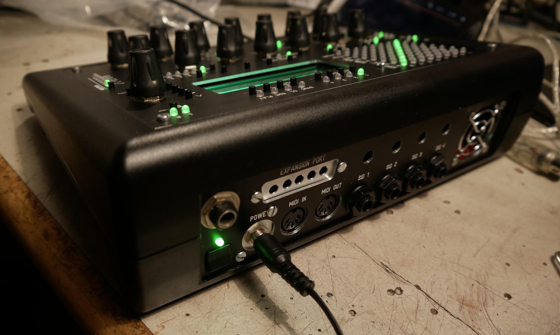
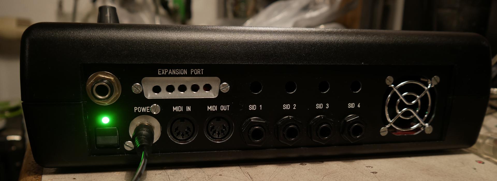
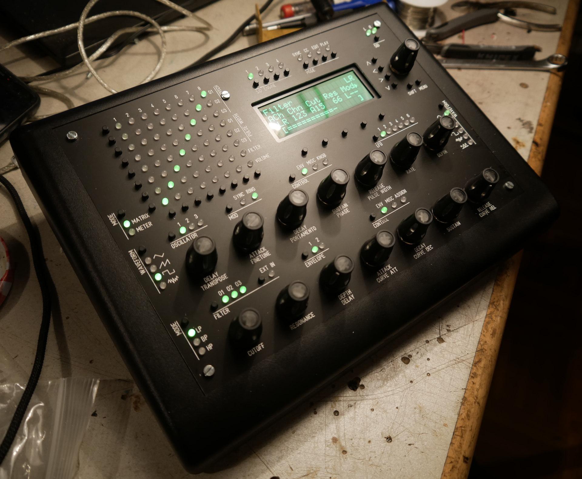
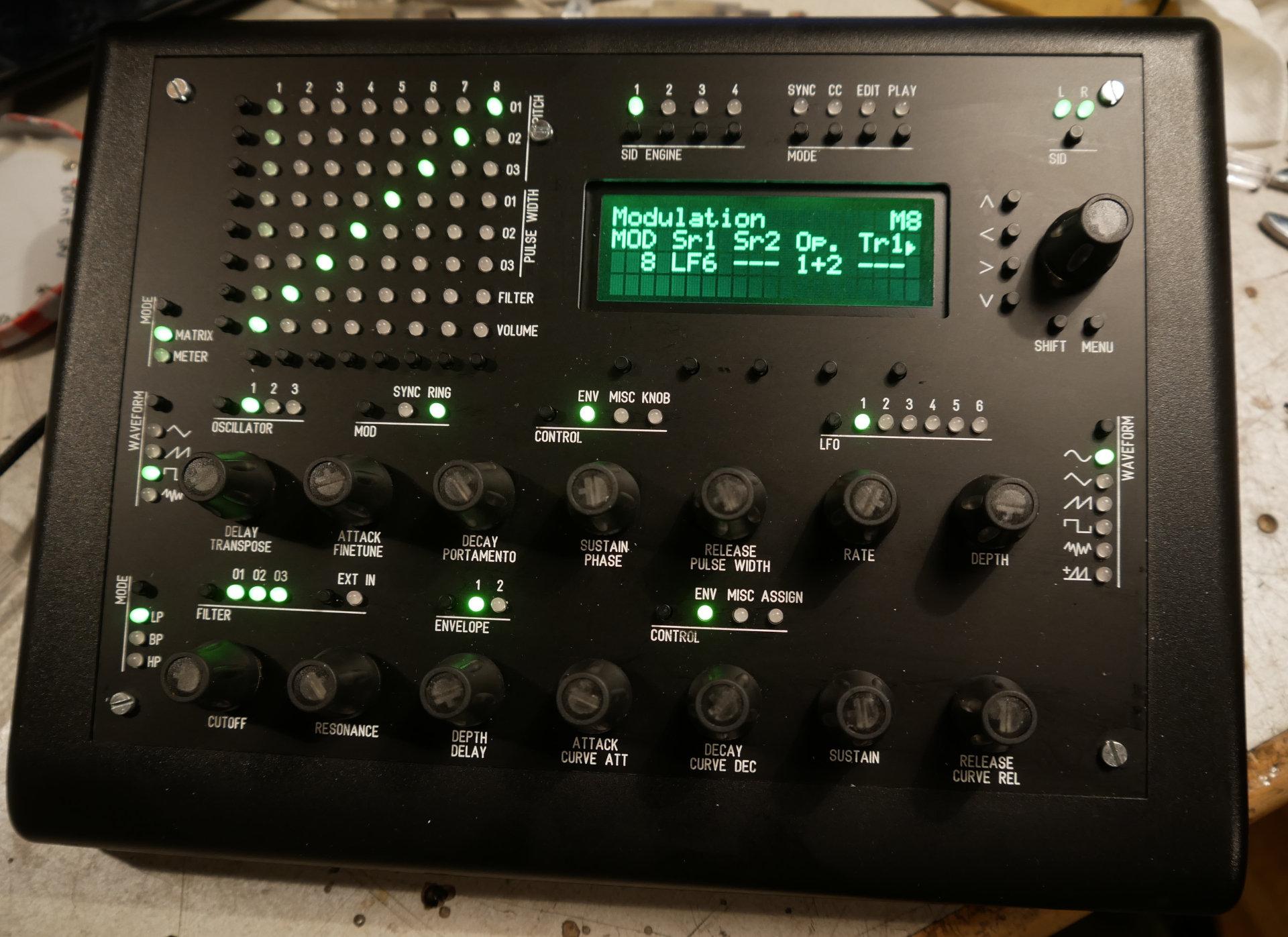
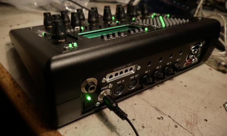
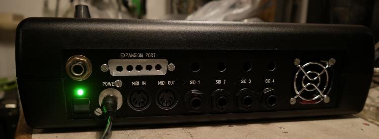
i made a passive design, since the fan which came from mouser, was dead from the beginning... since it is a 6582, it was not going very hot anyway... but i drilled Holes into the pcb under the SID-Sockets, and cut aways some plastic from the socket too. i too drilled some holes in the plastic body under the Main-PCB too, the backside off the SID should be enough to get rid off the hot air...

-
... and sound...
-
about MB-NET http://www.ucapps.de/midibox_sid/mbsid_v2_communication.pdf http://www.ucapps.de/mbhp/mbhp_core_v3.pdf http://www.midibox.org/dokuwiki/lib/exe/fetch.php?media=mb-6582:mb-6582_base_pcb_r2_color.pdf already resoldered all pins on core 3 and 4 replaced the pic 4 with a new pic... measured the can bus wires and diodes, replaced the Diode for core 4 removed R6 from core 4 reuploaded code for core 1 (aka 0) on the automatic reboot of mios, it didnt tell me that sid4 no mb-net... but after power off-on it says again: no response... ok it also tells me on startup: 1st screen: mios v 1.9h tk.... 2nd screen: [not here!] version 2.044 launching cs (what is not here????) 3rd screen: sid 4 not aviable no mb net response
-
thx got it... it was the ground pins... which are surroundet wit massive groundplanes (without traces that could make a thermal decouple). i heatet the.groundplane.with hot airgun,.and soldered all groundpins.again... worked " now.it says "sid 4 not aviable no mb net response" core is working, checked it by connecting a lcd to it... also reuploaded the firmware with id3... is the net a com between cores or between sid and core?
-
hei. i built the mb-6582 from an old kit... the 3 slave cores, provides a working a LCD, but not on the Master-Core, there i only see black-blocks... when i boot up the SID, i have Blocks all over the screen, then it refreshes, and i have blocks on first and third row off the display. What can be the problem? I already measured the connections from J15 to the PICs Pins. checked all J15 and PIC pins for Shortens against Neighor pins, and to ground and to +5V also removed all Shiftregisters, and Bank-sticks, and SIDs (is it necessery to have the Shiftregisters connected?) I also checked the SI-Pin off the HC165 - but they are not grounded or 5V... i also placed in a PIC from a working unit - and it is still black (so it is not the PIC) I already replaced the oscillator i checked all Resistors for their value - seems to be right... (i can upload new code, so it boots up proberly... also newest bootloader is on the PICs) - mike
-
thx i am working on the Frontpanels now, For the Button Board i use Aluminium Clear Acrylic for Screen-Encoder Section Opal Acrylic for the Motorfader Section - +++because, i plan to make RGB-LED-Boards so light up the Channelstrips in the same Color as they are in Ableton Colored... so i see groups, and have overview.... i want to mount them lower to the Encoders and make a Aluminiumplate to block the LED-Light from lightning into my eyes directly. i too make traces into the Acrylic, so i have less Illumination from strip to strip:

-
i use customcode based on mios32 - so i could enclude modified lcd functions (no midibox ng...)
-
i use J10 in combination with 74hc595 (latigidon display driver board) it seems to work for 56 screens (+8 from J15) how and where is the multiplexing logic for J10 programmed? and how to expand it to 80 screens? (hi update speed is not needet)
-
MIDIbox of the Week (MIDIfied Korg Polysynth by Francois)
Phatline replied to TK.'s topic in MIDIbox of the Week
i tryd to midify a old home organ (where every key was wired to lots of voices - without any logic...) at least there i had a lot off noice from the microcontroller, and bleeding.... but it worked - except from the noise - it worked - maybe ti would helped to use a lot of capictors to LPFilter the shiftregister outputs.... i gues the Relays terminate the digital-noise/transistor bleeding - so you get a clean solution. -
i am always interested into stm32F4 cores and stuff --- but RE_ take it - i am not interested into all off it --- but you will need all off it to build a seqV4 - so RE_ take it!
-
(at least he didnt answer me - i didnt bought it - so it may be aviable) better you send him a PM - maybe he has no email notification for topics...
-
about the things above... well most of the things you dont need... you need 3x DINX4 1x DOUTx4 2x 2x40 LCDs 17x encoders a lot off buttons and LEDs 1x core 1x DIN MIDI much wires... a custom frontpanel big breatboards - to build a custom UI better go to V4, search the flearmarked forum for a "wilba" frontpanel pcb, and a stm32F4 core with discovery board, and a Midi IO Board Frontpanels you can order from "the beast" from UK.
-
ok next step... "Mute" & Solo Buttons needs some external DINX and DOUTX boards (in order to make the SRIO-Gain short)