Phatline
-
Posts
1,285 -
Joined
-
Last visited
-
Days Won
72
Content Type
Profiles
Forums
Blogs
Gallery
Everything posted by Phatline
-
thx
-
hei i have those: SAON11M9-LIN10K I dont understand this touch feature... When my finger is the Ground/Touch, then there is still a plastic between the Fader and my finger, how does this work? (i have read till page 11 off this tread, but didnt found anyone questioned this...) do i need this (not in stock) chrome Fader-Lever? https://www.reichelt.de/at/de/faderknopf-gerippt-t-lever-chrome-knopf-18-5x1-5vc-p73957.html?&trstct=pol_14&nbc=1
-
i measured mine (with nothing connect then the usb-cable: 40°C measured with a infrared-"gun"
-
have to order some things... but looking good up to now...
-
 ps: cant see much off the vector board.... so its a bit watching in the magic "glas kugel"
 -
could be... you can try to filter out some psu-spikes by soldering a 100nf (maybe add also a 1uF or higher for too more stabilize the psu as addition) cap between + and - on the potis legs (most off the time these are the outer 2 legs off the trio)
-
look into ng documentation if there can be set a offset for the middle position so it stays on a position... because pots directly to the core is always a bit random... better use for example: http://www.ucapps.de/mbhp_ainser8.html then you have less random values also check the quality off PSU...off course a faulty pot can be the reason too
-
hmmm has to do with UART because when i add follwing line to mios_config.h #define MIOS32_DONT_USE_UART the board is working normal, i dont know what UART in this sense does? (USB-midibports??? Din-Midiports?) i dont know this is all i can do, the rest has to be done who knows this application
-
this is writing while building (for those who looking into this tread, and having a glue...)
-
i jumpered J27 in order to come into bootload-mode... (in order to upload new code...) then downloadet the actual bootloader, and made sure that i used the correct LPC1769 since mine is a 1769 then dowloaded the actual github zip from https://github.com/midibox/mios32 set the environment variables to lpc... restardet built the NG-code from the downloadet github.... ("make clean", then "make") uploadet the build project.hex removed the J27 jumper (then mios made a softreset mios writes: no response from CLCD.... (off course nothing connected) Init DHCP PHY initialized SD Card not found no problem up to this point but after reconnecting the USB-Cable (aka hard-reset) it goes into HARDFAULT ---aka blinking rapid so it is confirmed the actual NG-Firmware was not tested for a LPC-Core (maybe someone made changes, but tested it only on STM32?
-
cant say, may a other can help, but from where to you have that NG Version, because on http://www.ucapps.de/mios32_download.html i see only 1.036! (i searched, and wanted to look if this also happend to a virgin ng...)
-
ok, cant say what the display says (since it there is no) but the board led is blinking rapid. and mios studio does not recognize the board. i tested it on the LPC-Core, plugged into my laptop when i plug the usb-cable to a wall-5V adapter, its not blinking. so yes - this is a software thing, not a hardware. about mios-config... there is a lot activated.... do you use all the things in there? (#define MIOS32_SRIO_NUM_SR 32 and so on...)
-
LPC or STM?
-
Stripped-Down port of MIOS32 core on STM32F407 (HAL based)
Phatline replied to marcos_ee's topic in MIOS programming (C)
go in mios32_config.h (a file in the root of your project) and deactivate all you dont need with: #define MIOS32_DONT_USE_SYS #define MIOS32_DONT_USE_IRQ #define MIOS32_DONT_USE_SPI #define MIOS32_DONT_USE_SPI0 #define MIOS32_DONT_USE_SPI1 #define MIOS32_DONT_USE_SPI2 #define MIOS32_DONT_USE_SRIO #define MIOS32_DONT_USE_DIN #define MIOS32_DONT_USE_DOUT #define MIOS32_DONT_USE_ENC #define MIOS32_DONT_USE_AIN #define MIOS32_DONT_USE_MF #define MIOS32_DONT_USE_LCD #define MIOS32_DONT_USE_MIDI #define MIOS32_DONT_USE_OSC #define MIOS32_DONT_USE_COM #define MIOS32_DONT_USE_USB #define MIOS32_DONT_USE_USB_MIDI #define MIOS32_USE_USB_COM #define MIOS32_DONT_USE_UART #define MIOS32_DONT_USE_UART_MIDI #define MIOS32_DONT_USE_IIC #define MIOS32_DONT_USE_IIC_MIDI #define MIOS32_USE_I2S #define MIOS32_DONT_USE_BOARD #define MIOS32_DONT_USE_TIMER #define MIOS32_DONT_USE_STOPWATCH #define MIOS32_DONT_USE_DELAY #define MIOS32_DONT_USE_SDCARD #define MIOS32_DONT_USE_ENC28J60 then strip down all you dont need in your app.c.... if you have to include stuff from mios, copy it into your project directory, and include it with "display.h" instead of <display.h>, strip that file down (remove all stuff that is for other microcontrollers like the lpc, or other things you dont need) and maybe you got an glue, whats going on.... cant say more, but would really like see mios on a better faster bigger microcontroller then the stm32f407vgt6, since my project itself is already limited by the ram and flash capabillitys...hopefully someday somone comes that have the will and knowledge to port that... i dont have the knowledge (so forget me) -
hmm, i would first jumper all J5A/B/C - if they are open... so you have no noise from the ADCs... I know USB has nothing to do with ADCs, but that i would do first ( because that happend often when it not booted up) A virgin NG1.037? or somekind modified? (like the font thingi?) post what you have in "mios32_config.h" else i dont know, mostly i get hardfault when writing negtativ values intos unsigned integer variables (aka use s16 instead of u16 variables), or doing mess with custom freertos tasks.... i am really no expert for NG... you could post the code here (zip) and i can try if it does the same, have a stm or lpc here to test..
-
linux oder windows oder mac? hab bisher nur in linux gearbeitet, da geh ich immer auf: /etc/environment und kopier dann immer für STM32: PATH="/home/autark/midibox/gcc-arm-none-eabi/bin:/home/autark/program:/usr/local/sbin:/usr/local/bin:/usr/sbin:/usr/bin:/sbin:/bin:/usr/games:/usr/local/games:/snap/bin:/home/autark/app:/home/autark/midibox/gcc-arm-none-eabi/arm-none-eabi/bin" MIOS32_PATH=/home/autark/midibox/mios32 MIOS32_BIN_PATH=/home/autark/midibox/mios32/bin MIOS32_BOARD=MBHP_CORE_STM32F4 MIOS32_FAMILY=STM32F4xx MIOS32_GCC_PREFIX=arm-none-eabi MIOS32_PROCESSOR=STM32F407VG MIOS32_LCD=universal und für LPC PATH="/home/autark/midibox/gcc-arm-none-eabi/bin:/home/autark/program:/usr/local/sbin:/usr/local/bin:/usr/sbin:/usr/bin:/sbin:/bin:/usr/games:/usr/local/games:/snap/bin:/home/autark/app:/home/autark/midibox/gcc-arm-none-eabi/arm-none-eabi/bin" MIOS32_PATH=/home/autark/midibox/mios32 MIOS32_BIN_PATH=/home/autark/midibox/mios32/bin MIOS32_BOARD=MBHP_CORE_LPC17 MIOS32_FAMILY=LPC17xx MIOS32_GCC_PREFIX=arm-none-eabi MIOS32_PROCESSOR=LPC1769 MIOS32_LCD=universal rein (ich hab mir diese textblöcke abgelegt, und wo abgespeichert, das ich nur noch copy paste machen muss), ich vermute unter windows kannst dir einen script schreiben, der die entsprechende Variable EXPORTIERT, z.b. auch mit einen einfachen dos-fenster, wost den skript startest, und lpc oder stm reinschreibst, und dann wirds exportiert... aber wie genau? keine ahnung, und MAC 0 ahnung. und starte dann neu, ab da an sind meine SYSTEM VARIABLEN (zu linux: environment variables) dauerhaft gespeichert... falls ich dann ein älteres projekt wieder bearbeite, stell ich auf LPC um, und starte neu... ...aber hast schon recht... das ist müßig... war ich bisher zufaul mir mein leben zu erleichtern ;)
-
@ cherry: the switch itself you can get already from eg https://www.reichelt.de/tastaturzubehoer-c8099.html?ACTION=2&GROUPID=8099&SEARCH=*&START=16&OFFSET=16&CCOUNTRY=445&LANGUAGE=de&r=1&SID=967792150a00d890464504461a66ae529d97182e528c945af4544 caps: amazon, alibaba,.maybe.some thing like that: https://www.amazon.com/dp/B00FYO8EDC/ref=mp_s_a_1_5?keywords=flat%2Bkeycaps&qid=1675511770&sr=8-5&th=1&psc=1 https://www.cherrymx.de/en/dev.html the low profile is maybe interesting....
-
@poti; if the shaft's center is in the end on the same position - so same frontpanel holes can be used.... and: when soldering the thing: first mount the pcbs with loose potis on the frontpanel then solder it (and document this in the "how too build"... @ - : use thermal destress traces (cant remember the kicad word) when using groundplanes, so you can desolder the the poti much easier.
-
passt scho ; ) next quest - michi.
-
you work with local files in the project folder? or do you put the files in the mios-path? if you put your folders in the project folder you have to go a other route: * my example file "tm_V4" >>> try to "make" it, * and study what i have written with "" and <> include "blabla.h" (is a local file - so you have to put the file in this project folder) include <blabla.h> (is a file in the mios path) > so you have to put the file in the mios-path it would be usefull if you zip your project, post it here - to see how you work, and what may the problem is. tm_V4.zip
-
make clean make ? and change in headerfile: extern const u8 GLCD_FONT_JBIG[]; to extern const u8 glcd_font_jbig[]; in the makefile low and high letter dont cares, but i think in headers you have to write it exact like it is written in the font.c.... (but maybe i am wrong)
-
i have really cheap and old (but unused) green backlight 2x40 Screens at home, i dont need them (you pay the postage and they are yours) i bought 10 off them decades ago, actuall i only use SSD1306 Displays - i will not need the 2x40 anymore. where are you from (EU?)
-
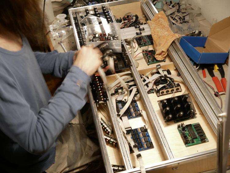
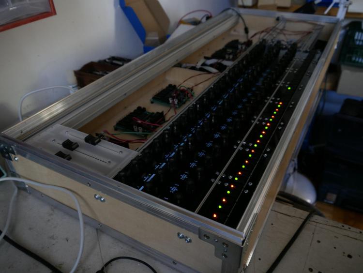
control hardware yes, if it is well documentadet on the wiki (shematic, board screenshot) I too work with kicad since decades... and very sucessfull now with my actual projects - i was wondering but i planed it in kicad, and most off the boards where working 100% out off the Box (pick and place JLCPCB), ok i had a design fault on one, but that was solved with a wire-done. actual projects http://wiki.midibox.org/doku.php?id=triggermatrix5 http://wiki.midibox.org/doku.php?id=daw-ableton http://wiki.midibox.org/doku.php?id=openpad software: cant help, write my own Mios-based code, havent look into MidiboxNG - since it is a script, for me more easy to write it directly in C, (need to understand all, else i understand/learn nothing...) - so no help from this side had good expierences with jlcpcb... also with the Pick and Place service FrontPanels: maybe cheap CNC-Laser-Cutting from pcbway? https://www.pcbway.com/rapid-prototyping/CNC-machining/CNC-Laser-Cutting-Services.html suggestions? Maybe use Eurorackformat, so it can be used outside of your box too? suggestion, where usefull (wo sinnvoll) use J89 Serial Chain directly onboard (like encoder with ledring boards) to reduce wireing - a simple button board dont needs that of course.... *** if you go the Serial Chain way, then buffer the Serial chain on each module to keep the digital Signal Quality intact (very necessery) *** buffer: search for SN74LVC1G17DBVR in this shematic: http://wiki.midibox.org/lib/exe/fetch.php?media=phatline:blm16x16-shematic.pdf maybe use pick and place ready smd technologoy like i did: that makes it smaller, and less to solder, less to debug, the plastic packages stays in china, more economical special when ordering more pcbs, by that of course a module should fit all the boxes (a exotic 1 man needs it module 10times fabricated is 9 too much...) i think i dont have to say, that you should choose "Basic" Parts, and not "extendet parts" on JLCPCB, - off course on most modules you have at least one or two extendeet parts... but for example a DINX4 or DOUTX4 can be made with basic parts only... but when you also want to pick and place all the pin headers - these are extendet parts, how ever ... you may look on my last modules a bit http://wiki.midibox.org/doku.php?id=tm5-dindoutgate http://wiki.midibox.org/doku.php?id=doutx2dinx1 if you use long cables to your Displays + u use more displays then one - on the modules, use a display driver (no more walking lines) http://wiki.midibox.org/doku.php?id=displaydriver-smd what else? if you make ground or other PCB-Planes, then setup kicad that it make 1-2mm space arround solderpoints - else the Soldering Man could make shorts, or electrocemical oxidations or solder flux-low-residance could make there some problems (after years), special when the Solderstop-Pain is scratched a bit... ... and so on... PS i hate this wooble feeling off this LeMec Buttons (the last board you posted) - these Buttons are not good (for my taste) I love to work with this ones: https://www.reichelt.de/at/de/eingabetaster-schaltspannung-24v-fuer-led-sw-dtl-2-sw-p7248.html?&trstct=pos_0&nbc=1 they are expensive, but they last decades (in use, and also if you order 300 off them and let them lye arround, after 15 years they still work) They have good CLICK, like a mechanical Keyboard. your leMec Buttons are like a mixture off Rubberdome and "i have to touch this buttons into one direction X=0 Y=0 else it want switch" or you could use: https://www.midiphy.com/en/shop-details/140/4/5pcs-matias-quiet-click-tactile-switch- they are cheap but big... (aka take away a lot of Frontpanel space) or maybe you use cherry switches or simulars.... they are all 1000% better then this leMecs... ( you notice i hate them)
-
ok i got it... if you have for example follwing Shiftregister Chain- Scenario: DINx3 > DOUTx4 > BLM (instead of BLM > DIN > DOUT... which is not possible because of not having a J8/9 output on the BLM) go to blm_scalar.c and change following: ///////////////////////////////////////////////////////////////////////////// //! Initializes the BLM_SCALAR driver //! Should be called from Init() during startup ///////////////////////////////////////////////////////////////////////////// s32 BLM_SCALAR_Init(u32 mode) { // define default configuration (can be changed during runtime) int mod; for(mod=0; mod<5; ++mod) {// count thru Scalar Modules // DOUT int mod_sr_offset = (3 * mod) + 4; // 4: DOUTX4 OFFSET 3: 1-Cathode, 2-Color1, 3-Color2 blm_scalar_config.dout_cathodes[mod] = mod_sr_offset + 1; int colour; for(colour=0; colour<2; ++colour) blm_scalar_config.dout[mod][colour] = mod_sr_offset + colour + 2; // offset 2..3(..4) // DIN blm_scalar_config.din[mod] = mod + 1 + 3; // 3 = DINX3 OFFSET } ....................................... have fun!
-
now i need this for the DOUT-Registers... i got the 16x16 working with following code .... but the Extra-XY stay dark - any Idea? cant get forward, since Latigid Ons BLM has no J89 thru, i have to put the BLM at the end of the SR-Chain (3xDIN, 4xDOUT in front off the BLM) ///////////////////////////////////////////////////////////////////////////// //! This function prepares the DOUT register to drive a row DOUT-SR-OFFSET HERE!!!!!!!!!!!!!!! //! should be called from APP_SRIO_ServicePrepare() ///////////////////////////////////////////////////////////////////////////// s32 BLM_SCALAR_PrepareCol(void) { // increment row, wrap at 8 if( ++blm_scalar_selected_row >= 8 ) { blm_scalar_selected_row = 0; } // select next DOUT/DIN row (selected cathode line = 0, all others 1) u8 dout_value = ~(1 << blm_scalar_selected_row); // apply inversion mask dout_value ^= blm_scalar_config.cathodes_inv_mask; // output on CATHODES* registers u8 SRo_off = 4; //Shiftregister offset int mod; for(mod=0; mod<5; ++mod) { int sr = blm_scalar_config.dout_cathodes[mod]; // 5: Module-Nr if( sr ) { MIOS32_DOUT_SRSet(sr-1 + SRo_off, dout_value); } // SR-CHain: BLM > Dout.... //if( sr ) { MIOS32_DOUT_SRSet(sr+3, dout_value); } // SR-Chain: DoutX4 > BLM } // output colours for(mod=0; mod<5; ++mod) { int colour; // 5: Module-Nr for(colour=0; colour<2; ++colour) { // 2: Color-Nr int sr = blm_scalar_config.dout[mod][colour]; // Module 8 Rows Color Blink u8 STEPs= blm_scalar_led[mod][blm_scalar_selected_row][colour][0]; int val; if (blinky && BLM_BLINK_ACT) { // turn of the blinking Steps u8 FLAM = blm_scalar_led[mod][blm_scalar_selected_row][colour][1]; // compare FLAM and STEPs with Bitwise XOR! val = FLAM ^ STEPs; } else { val = STEPs; } // Set it if( sr ) { MIOS32_DOUT_SRSet(sr-1 + SRo_off, val); } //Shiftregister offset, val); } // SR-CHain: BLM > Dout.... //if( sr ) { MIOS32_DOUT_SRSet(sr+3, val); } // SR-Chain: DoutX4 > BLM Geht zumindest für ie Hauptmatrix 8080 /// ///////////////////////////////////////////////////////////////////////////////////////////////////////////////////////////////////////////777 } } return 0; }