TK.
-
Posts
15,248 -
Joined
Content Type
Profiles
Forums
Blogs
Gallery
Everything posted by TK.
-
@jaytee what does upset you if I recommend to wait for the publication until the quality of the board has been proven? Best Regards, Thorsten.
-
I recommend to have a single run first to ensure that the layout translation was successful. Once proven, the gerbers can be provided as open source (under whatever license) Best Regards, Thorsten.
-
-
Probably the UIP task (which handles OSC) hasn't enough RAM so that a stack overflow happens. Could you please try this one: http://www.ucapps.de/mios32/midibox_seq_v4_093_pre6.zip Best Regards, Thorsten.
-
Ok, this is the classical little/big endian swap ;-) Please try this version: http://www.ucapps.de/mios32/midibox_seq_v4_093_pre5.zip Best Regards, Thorsten.
-
Please try this version, bytes are swapped now (untested at my side, since I can't use osc2midi) -> http://www.ucapps.de/mios32/midibox_seq_v4_093_pre4.zip Note that this pre-release also provides a new feature: Chord3 Parameter layer as proposed by EsotericLabs! :) Ok, I added following item to the wish list: PC Send behaviour: option to avoid that already selected PC will be re-sent The use case is the following: somebody connects the synth to MIDI OUT and doesn't want to power-cycle MBSEQ Or somebody wants to tweak parameters while a pattern is playing, but wants to reset to the sound setup when another (or the same) pattern is selected. Therefore I've to ensure that a PC will be sent consistent with start or pattern change. But I understand your use case, and assumed that you are aware of the limitations, you will find your way... No, this doesn't exist, but I don't understand the use case. Usually somebody would use the transposer to achieve this. The transposer especially allows you to avoid that tracks which should not be transposed (such as drum tracks) are not affected. such a possibility doesn't exist, and it's also counter productive, because the MIDI messages will delay the first notes! Best Regards, Thorsten.
-
So, this means that with the changed version, MBSEQV4 sends MIDI events correctly now, but the receive part is not working, right? Which probably means that I've to shift the bytes for the receive routine as well (which wasn't clear from your first message) Best Regards, Thorsten.
-
Thanks for the hint! Could you please check if OSC MIDI Transfers are correctly working with this version? -> http://www.ucapps.de/mios32/midibox_seq_v4_093_pre3.zip Best Regards, Thorsten. P.S.: I will process the feature requests of the last weeks sooner or later - they are not lost!
-
Big Picture: the MBSID V2 sound engine has been 1:1 replicated and delivers identical results. This has been proven with a virtual prototype (the AU instrument) and with direct connection to hardware (more about this below) The number of engines running in parallel is only limited by available RAM and chip performance. E.g. running 4 engines which service 8 SID chips isn't a big problem, and even on the STM32F1 there was enough headroom to increase the update frequency (which is only 500 Hz on the PIC based MIDIbox SID V2) Only exception: the oscillator phase offset feature is not available because it required special treatments which conflict with servicing multiple cores. This feature requires that oscillators will be reset and a uS accurate delay between 1..250 uS takes place to release the oscillators. It will be very difficult to support this directly on the core which handles the engines, because 250 uS delay has a much higher impact than on a PIC. While a PIC could only execute 2k instructions during this time, a STM32F4 could execute ca. 40k instructions, and it would need this to service more than one engine... However, there are solutions to support even this feature (see below) Missing parts at the software side: the entire control surface Currently the synth can only be controlled from a SysEx editor (e.g. the Ctrlr based) I prepared the CS by introducing SCS, which is for example integrated into the MIDIbox CV V2 application (the software architecture is similar to MIDIbox SID V2) possibility to store/restore patches and ensembles on SD Card For somebody who is good in SW programming it shouldn't be a big deal to implement this, especially since the basis is already available in other applications. It just needs some time... Hardware side: the serial shift registers could be connected to J19, for CS lines individual IO pins are required (e.g. J10B + level shifter). I tried this at the beginning of the project with a STM32F1 core and it worked. alternatively an existing MIDIbox SID, MB6582 or sammichSID can be controlled from a MIOS32 core via MBNET (-> the CAN interface). This was my focus during development, because I was able to use my existing hardware It worked as well, the appr. extensions are in the official PIC based MIDIbox SID V2 firmware (I just noticed: I added it 6 years ago! ;-) but actually the preferred solution today would be a connection to FPGA based SID via J19 CS lines available via this SPI connection as well. And the FPGA could support additional features such as the (missing) oscillator phase offset feature to offload the firmware Note that I'm in contact with the FPGA developer - at least I would like to try it out :) Alternative solution: a software based SID emulation could be developed, running on STM32F4 Advantage: the STM32F4DISCOVERY has already an Audio DAC integrated, which means that this would probably be the cheapest way to get some nice SID sounds :) Misc: no documentation available I'm sure that once MIDIbox SID V2 will be released for MIOS32, new users will come up with new feature requests Actually it should also be considered a MIDIbox SID V3 with different sound engine architecture to utilize the new possibilities of MIOS32 The last three points somehow blocked my motivation when I compare with that what I already created with the PIC based MIDIbox SID V2 I noticed that for myself there wouldn't be a big advantage anymore, because I'm happy with MIDIbox SID V2 as it is. So - if somebody else feels motivated to continue and maintain this work, and to support future users over long term feel welcome! Best Regards, Thorsten.
-
Then your DAW has to translate the ASCII characters to values which are put into the SysEx stream Or you could generate the values at this website: https://www.branah.com/ascii-converter Best Regards, Thorsten.
-

Speed up scanrate of NG by kicking out other scanroutines?
TK. replied to FantomXR's topic in MIDIbox NG
Yes, you could remove unusued functions from APP_SRIO_ServiceFinish() in src/app.c E.g. remove SCS functions if the SCS isn't connected to DIN pins. remove MBNG_MATRIX_GetRow() if no BUTTON_MATRIX is used remove MIOS32_ENC_UpdateStates if no encoders are connected That's all what can be improved, the additional overhead is caused by the application itself, at the end you would come to a downstripped version like MIDIbox KB ;-) However, if it turns out that the removals from APP_SRIO_ServiceFinish help, then I could add runtime options to disable certain functions in future so that no recompile is required. Best Regards, Thorsten. -
yes, a video would be interesting Best Regards, Thorsten.
-
We've up to 16 parameter layers + up to 8 trigger layers, therefore dedicated views are required Best Regards, Thorsten.
-
I guess that you want to send text from one MIDIbox to the display of another MIDIIbox w/o the need to specify the text as hex numbers? No, this isn't supported (yet) Best Regards, Thorsten.
-
Speed up scanrate of NG by kicking out other scanroutines?
TK. replied to FantomXR's topic in MIDIbox NG
In src/mios32_config.h you could change the number of DOUT pages from 32 to 1: #define MIOS32_SRIO_NUM_DOUT_PAGES 1 This will increase the scan rate by factor 32 Compile will fail with: src/mbng_matrix.c:53:3: error: #error "not prepared for != 32 pages - many variable types have to be adapted!" src/mbng_matrix.c: In function 'MBNG_MATRIX_DOUT_NotifyReceivedValue': the appr. "#error" line has to be removed It says, that all LED_MATRIX related functions won't work anymore, such as LED rings Best Regards, Thorsten. -
Yes, that's exactly the purpose of the root note :) You are now able to transpose from the track layer w/o the usage of an additional loopback track. Best Regards, Thorsten.
-
Hi, thanks for pointing this out! The table was correct, the schematic wrong. It's corrected now: http://www.ucapps.de/midibox_seq/mbseq_v4_dio_wilba_layout.pdf Best Regards, Thorsten.
-
The enhancements of the last months are now officially available (and documented): MIDIboxSEQ V4.092 ~~~~~~~~~~~~~~~~~ o new parameter layers for track specific root note and scale Root selection strategy: if Root is assigned to any parameter layer of a track, the layer can either select the global root selection ("Glb") or set the root note for each step explicitely. The global root selection is configured in the FX->Scale page, it's either "Keyb" (for MIDI keyboard entry) or C, C#, ... B The local root selection is C, C#, ... B Notes and Chords will be transposed accordingly if the track is in Normal mode (and not in Transpose or Arpeggiator mode) Similar for Scale: it can override the globally configured scale of the FX->Scale page for each step. o new drum configurations: 4*16/2*64, 4*16/2*128, 4*16/1*256 o new configuration option in Track Mode page: "Note Last/First" Allows to specify, if the transposer should take the last or first played note (previously it always played the last note) o new configuration option in Track Mode page: "STrg" (Step Trigger). If activated, the step progression will be controlled from the transposer bus, hence it can either be triggered from a loopback track or from an external MIDI device (MIDI keyboard, sequencer, etc.) Note that each track can be assigned to a dedicated transpose bus (4 busses are available), this allows to control 4 independent step progressions for all 16 tracks. o individual steps of CC, PitchBender, Program Change and Aftertouch layers can now be disabled so that they won't play. Turn the encoder to the rightmost position (value 128) Also the init value has been changed: for these layers, the steps are now disabled by default. For CCs please change the init value by yourself in the UTIL->OPT page (option #12: Initial CC value) o new behaviour of CLEAR button in recording mode: it clears only the selected step (instead of the entire pattern). During live recording it will clear the "played" steps while the button is pressed. o new CC functions which can be configured in MIDI->ExtCtrl. page: o Play/Stop: allows to assign the PLAY button to a CC o Record: allows to assign the RECORD button to a CC o new option in Groove page: Sync Allows to sync the groove to the global reference step (RefS) or to the local track step o fixed G# transpose Best Regards, Thorsten.
-
See core/seq_chord.c: up to 6 notes, up to 6 chars. In the step display I will print the first 4 chars, this should be considered while naming the chords. Yes, just provide the table in C format so that I can directly take over w/o translation Best Regards, Thorsten.
-
That's exactly the intention: the work flow will be a bit different (hopefully more ergonomic), but I don't plan to add a new function which won't be accessible with the old frontpanel. Duo-LEDs won't be required, but if available, different colours will allow to show a bit more information. E.g. Step View: loop range could be highlighted. Track/Layers/Instruments: second LED could show muted parts Bookmarks: second LED could show already allocated bookmarks Mute will show muted and soloed tracks (*) (*) a track solo function is currently not available - if I add this feature, it will rely on a second colour, otherwise the handling will be too confusing if a certain track doesn't play and you don't know, if it's because of a mute, or because other track(s) is/are soloed. Best Regards, Thorsten.
-
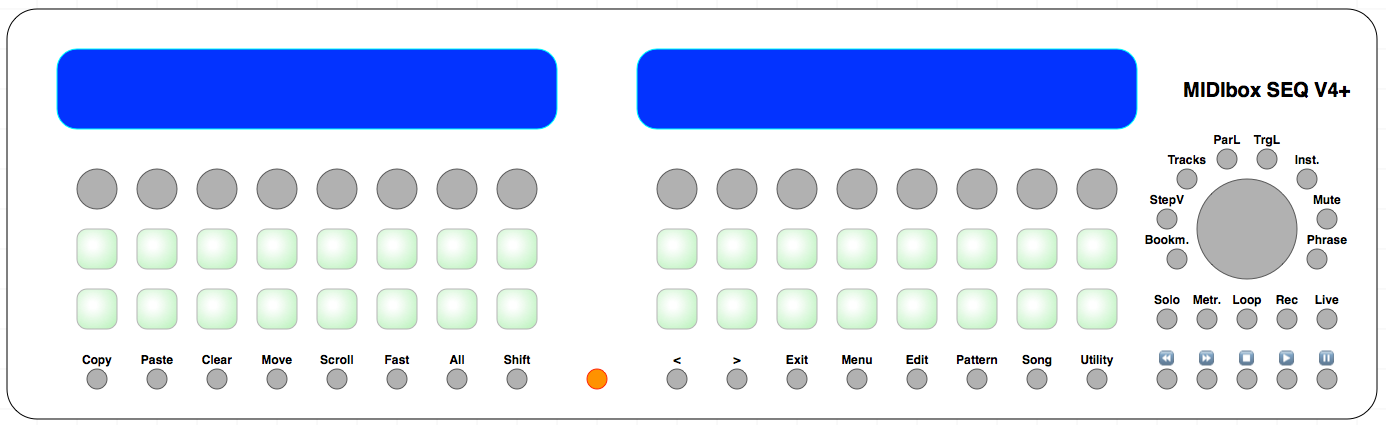
I think that the new "selection button row" consisting of 16 buttons and duo-colour LEDs will be a big + :) The 8 buttons around the datawheel allow to assign a function to this row. The functions are: Step View Tracks Parameter Layer Trigger Layer (Drum) Instrument Track Mute (and evtl. Track Solo) Bookmark Song Phrase Especially for the first 5 functions will improve manual editing flow, having all 16 views/tracks/layers/instruments selectable in a dedicated button row should speed up switching. Here another picture which shows the function assignments to the new buttons: Feedback welcome! Best Regards, Thorsten.

-
yes
-
Such a configuration doesn't fit to the intended use case. Actually only a single bank is supported, and it's intended that all display elements have either an assigned EVENT for this bank, or that they are not assigned to any bank. Best Regards, Thorsten.
-
I checked this with LRE2x8 - the LED rings will be updated Or do you mean LED rings, which are assigned to various banks, but not to the selected bank? Then I guess that they won't show the updated value until the assigned bank will be selected. Best Regards, Thorsten.
-
Yes, since today this is possible again: Note that this will change the entire session, not only the .NGC file Which means that you've to duplicate the .NGR script Best Regards, Thorsten.