ilmenator
-
Posts
2,304 -
Joined
-
Last visited
-
Days Won
37
Content Type
Profiles
Forums
Blogs
Gallery
Everything posted by ilmenator
-
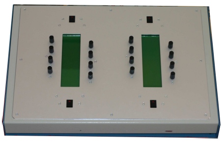
I have one criticism about the layout: I wanted to use textool-sockets for both the small and the large ICs but cannot, because they are positioned too close to each other - see the picture. Yet there would be enough space on the board... Mike? Best regards, ilmenator Burner.JPG
-
...and don't forget to call the Display_Init routine after switching it on again. Best regards, ilmenator
-
Before entering this thread I did not even know I was an environmentalist. ;) Maybe we should get back to the Lazertran topic anyhow? Best regards, ilmenator
-
Never mind, I am not the one standing for political correctness or anything else in that matter. I still believe that I myself can contribute my little share, though. Sometimes I try to convince others of that :). Best regards, ilmenator
-
Hey, I like that ;D... let's see how many people jump the boat and help with that. Btw, the rotary encoders around the display already do have a button function in our prototype... Best regards, ilmenator
-
At least here in Europe your local nameities must provide some sort of recycling system for those ''dangerous'' types of waste. Usually they have collecting points, sometimes even mobile ones, so that you do not need to drive far to get rid of your stuff. For privateers this service is usually free of charge. The people at the collecting points like it if you can tell them what type of fluid/waste you bring them, but even if you claim to have found a canister in your cellar and have no idea about what it contains they will gladly accept your stuff. FeCl can damage your eyes when getting in contact, even in low dilutions. I imagine it can also unbalance your local sewage plant. So be better than the rest and bring it where it should go. Best regards, ilmenator
-
Hi Adam, thanks for offering your help - it is much appreciated here! I was not involved in the SWT vs. standard Swing decision, and I cannot see any discussion on this in the documentation that we have. I think it was just something related to the look of the tool. In fact, one of the criticisms that the review commission had was that the tool's platform independency was never actually tested to a reasonable extent :(. TK wrote: There is quite some usability thinking that went into the user interface. Yet it is very ''dry'' and clear (you might call it ''unsexy''). I was considering some kind of graphical representations of envelopes on a third GLCD, but it would have turned out too complicated in this first implementation. Yet there is room for improvement: e.g. the vertical bar graph should be able to also represent negative parameter values. Currently it shows the MIDI value going from 0-127 (0-16384 for 14 bit parameters) - it would be nice to show the actual ''user'' value (see the chapter of the documentation discussing the user scales). With respect to the cost of those displays: you can find them regularly at ebay, and I payed 13,- Euros each for the ones I purchased for my own personal box. LED backlight included... Best regards, ilmenator
-
Well, that WAS my job as a lecturer... but this time it was fairly easy, the guys really did a good documentation job. Well, it would be possible, it is a modular thing, you know... But to be honest, it would result in a really big amount of work, because also the JAVA editor would have to be modified. On the other hand it should be fairly easy to modify the encoder positions to a more symmetrical layout ;), even if this implied a different 'screen setup' for the second LCD. Because stryd asked for more screenshots in another thread: Here you can see the Device select screen, the Module select screen and a demo Parameter screen. What we will really need is some help with the JAVA editor software. To make it more sweet to all of you, I am in the process of setting up a public SVN repository, so you can easily contribute or peek around the software. I will let you know once it is up and running. Best regards, ilmenator MIDIbox_GLCD_menu_Device_select_small.JPG MIDIbox_GLCD_menu_Module_select_small.JPG MIDIbox_GLCD_menu_Parameter_demo_small.JPG
-
You could also take a look at how the Oberheim Matrix-1000 is designed - see here: http://wolzow.mindworks.ee/analog/m1k.htm. Of course, one would not just build a clone of the Matrix... Best regards, ilmenator
-
Hello all, after more than half a year of development we are very proud to announce the MIDIbox GLCD, a universal synth editor. It consists of 16 rotary encoders with push-buttons grouped around two vertical 240x64 GLCDs (hence the name) and allows to edit up to 16 different synths (devices) at a time. Each device can contain up to 4x16 modules with 16 parameters each - that should be enough for even the more complex synths. Once it is configured through a JAVA application, it runs in stand alone mode. It can receive a synth's complete edit buffer and is therefore always in sync with the synth itself - e.g. if the waveform "SAW" is selected on the synth, MIDIbox GLCD knows about it and tells you on the display. Internally it runs on three core modules, the master module with a PIC18F4620, the slave module for the second display with a PIC18F452, and a MIDI merger module (18F452 or 16F877, as you wish), so you can connect both the synth to be edited and a keyboard to the MIDIbox GLCD. Also, there is an IIC MIDI module (USART bug in 18F4620), a stripped down LTC module for MIDI activity LEDs, and the usual DIN / DOUT boards. Last not least there are lots of banksticks in the box, a total of 768kByte for storing the necessary data. MIDIbox GLCD is capable of sending all known MIDI messages for controlling / editing synthesizers: note on/off, continuous controllers, RPN, NRPN, SysEx, and you can even use it when your synth only understands complete dumps of the edit buffer. It gives new value to all those late 80's, early 90's synth that come in a 1U rack mount case with a 2x16 character LCD and 6 buttons to edit the synth via a labyrinth of hidden menus and submenus. It is configured to work with your favourite synth by using a JAVA software and the MIDI implementation chart of your synth. That is the bad part about it: you need to do this yourself, as of now there is no parameter set readily available. The good news is that these parameter sets, once built by the user, can be exported to an XML format and thus easily imported by other users of the MIDIbox GLCD. This is the point where we probably need some help: in principle, the JAVA editor software is up and running, but it is still buggy in a number of ways. Now, if you are interested in this project, go to the Wiki and have a look here: http://www.midibox.org/dokuwiki/midibox_uc. It is all documented, you can download all the sources, it is all there. Please bear with us, as some of the english language documents have been created using automatic translation - expect to read some funny sentences ;D. Best regards, ilmenator edit: updated link to WIKI
-
Hey stryd, you are right, only the teaser is up there... sorry, I currently do not have access to the documents myself and I am back on a slow modem connection after a year of DSL (but that will change again very soon), Gertius will go to Australia for half a year or so tomorrow, but I hope that some of the other guys have time for uploading the stuff again very soon. I will send some emails to them right now :). Best regards and thanks for restoring that forum so quickly twin - I caught myself checking it every other hour... Am I an addict? ilmenator PS: One more teaser here... ;D
-
Thanks stryd! Actually I am trying to read one of those Korg RAM cards made for the M line of synthesizers. I have the connector set up and ready, and the SRAM Test v1.1 by TL does its job as expected - although sometimes the RAM address changes unexpectedly when moving one of the other encoders. Anyway, this does not matter to me because I only wanted to make sure that my wiring is okay. Now I have to design my own code, and seeing that there might still be a bug in TL's code I am even more motivated to go the C way. If you have any ready-made code for that, it is most welcome, but I think I should manage. You will surely see more questions arise, though... :) Best regards, ilmenator
-
Sorry for trying to answer my own post... I think it is just the other way round: #include "mios_wrapper/mios.h" #include "mios_wrapper/mios_vectors.inc" #include "macros.inc" get included in [tt]sm_simple.asm[/tt] and the labels are kind of "exported" to the C code?? Therefore [tt]sm_simple.asm[/tt] needs to be compiled before [tt]main.c[/tt]? Still a bit confused about this, I have to admit. Is there any recommended reading? Thanks, ilmenator
-
Thanks, I looked at the C based sm_examples. Now I wonder how the [tt]sm_simple.asm[/tt] is "included" into the C code? Is it only done by creating [tt]sm_simple.o[/tt] in the makefile and everything else happens automagically? I cannot find any include instructions in the rest of the code?? Best regards, ilmenator
-
Thanks TK, I've been doing some more digging and I have learned quite a lot. :) I have managed to compile large parts of the SRAM code mentioned above within my C application, among others doing things like replacing lfsr FSR1, SRAM_MAP by movff _FSR1L, SRAM_MAP_L . It was mentioned somewhere in another post. Still unsolved are things like movff POSTINC1, _PORTB which are really out of scope for me at the moment. Also, by looking at the [tt]main.asm[/tt] file in [tt]/output[/tt] I found out about the underscore thing - most of the time it seems to work like this, the strange thing is that I can leave out the underscore for [tt]TMP1[/tt], see this example ?? void SRAM_Read_Page_Loop(void){ _asm ; first latch movff TMP1, _PORTB bsf _LATA, SRAM_PIN_LATCH1_LE bcf _LATA, SRAM_PIN_LATCH1_LE ; enable port read mode setf _TRISB bcf _LATA, SRAM_PIN_CS bcf _LATA, SRAM_PIN_OE nop ; read data into PIC memory movff _PORTB, _POSTINC1 bsf _LATA, SRAM_PIN_OE bsf _LATA, SRAM_PIN_CS ; disable port read mode clrf _TRISB incf TMP1, F cpfseq TMP1 bra _SRAM_Read_Page_Loop __endasm; return; } I also took a deep look at the [tt]mios_wrapper.asm[/tt], there I am not sure why some of the MIOS functions have additional instructions and onthers not? Is it because the others are not implemented yet, or because there is no need for additional code instructions? Eg I am trying to use [tt]MIOS_HLP_GetBitORMask[/tt] without success, looking at the wrapper I see ;; -------------------------------------------------------------------------- .MIOS_HLP_GetBitORMask code MIOS_HLP_GetBitORMask _MIOS_HLP_GetBitORMask global _MIOS_HLP_GetBitORMask, so it is there and I thought I just have to add the underscore... but no joy :( Maybe I should just drop the SRAM assembler code snippets and do it all from scratch in pure C? Thanks for any input, ilmenator
-
Hello, I am currently trying to use some assembler code snippets described in this thread (http://www.midibox.org/forum/index.php?topic=4140.0) to access an SRAM chip connected to J15 of the core module within my C application. Basically I know how to use assembler code in C, but it seems like I do not fully understand how variables names are used in the assembler to C mechanism. Here come the errors I get when I try to compile my code. Assembling MIOS SDCC wrapper ========================================================================== Compiling pic18f452.c Processor: 18F452 ========================================================================== Compiling main.c Processor: 18F452 In file included from main.c:17: sram.c:83:3: warning: "/*" within comment sram.c:123:3: warning: "/*" within comment sram.c:185:3: warning: "/*" within comment _output\main.asm:506:Error [113] Symbol not previously defined (TRISA). _output\main.asm:506:Error [113] Symbol not previously defined (TRISA). _output\main.asm:507:Error [113] Symbol not previously defined (TRISA). _output\main.asm:507:Error [113] Symbol not previously defined (TRISA). _output\main.asm:508:Error [113] Symbol not previously defined (TRISA). _output\main.asm:508:Error [113] Symbol not previously defined (TRISA). _output\main.asm:509:Error [113] Symbol not previously defined (TRISA). _output\main.asm:509:Error [113] Symbol not previously defined (TRISA). _output\main.asm:510:Error [113] Symbol not previously defined (TRISA). _output\main.asm:510:Error [113] Symbol not previously defined (TRISA). _output\main.asm:512:Error [113] Symbol not previously defined (PORTA). _output\main.asm:512:Error [113] Symbol not previously defined (PORTA). _output\main.asm:513:Error [113] Symbol not previously defined (PORTA). _output\main.asm:513:Error [113] Symbol not previously defined (PORTA). _output\main.asm:514:Error [113] Symbol not previously defined (PORTA). _output\main.asm:514:Error [113] Symbol not previously defined (PORTA). _output\main.asm:515:Error [113] Symbol not previously defined (PORTA). _output\main.asm:515:Error [113] Symbol not previously defined (PORTA). _output\main.asm:516:Error [113] Symbol not previously defined (PORTA). _output\main.asm:516:Error [113] Symbol not previously defined (PORTA). ERROR! Now, this is the section that the errors originally refer to: void SRAM_Init(void) __wparam { __asm ;; disable the ADC which allocates the analog pins ;; only needed if controls pins are connected to port A movlw 0x07 movwf _ADCON1 ; put PortA in output mode bcf SRAM_TRIS_LATCH1_LE, SRAM_PIN_LATCH1_LE bcf SRAM_TRIS_LATCH2_LE, SRAM_PIN_LATCH2_LE bcf SRAM_TRIS_CS, SRAM_PIN_CS bcf SRAM_TRIS_WE, SRAM_PIN_WE bcf SRAM_TRIS_OE, SRAM_PIN_OE ; set control lines bsf SRAM_PORT_OE, SRAM_PIN_OE bsf SRAM_PORT_WE, SRAM_PIN_WE bsf SRAM_PORT_CS, SRAM_PIN_CS bcf SRAM_PORT_LATCH1_LE, SRAM_PIN_LATCH1_LE bcf SRAM_PORT_LATCH2_LE, SRAM_PIN_LATCH2_LE ; put PortE in output mode bcf _TRISE, 0 bcf _TRISE, 1 bcf _TRISE, 2 __endasm; return; } I know this because before adding an underscore in front of [tt]ADCON1[/tt], I got the same '_output\main.asm:506:Error [113] Symbol not previously defined (ADCON1)' error message as I get them for the TRISA now. The problem is that there is a macro #define SRAM_TRIS_LATCH1_LE TRISA in a header file included from the main.c that defines TRISA, but if I add the underscore in front of TRISA there I still get the same error message. When I look at the main.asm file in the \output folder, I can see that the macro gets translated to ; ; Starting pCode block S_main__SRAM_Init code _SRAM_Init: ;; disable the ADC which allocates the analog pins ;; only needed if controls pins are connected to port A movlw 0x07 movwf _ADCON1 ; put PortA in output mode bcf TRISA, 0 ;bcf TRISA, 1 ;bcf TRISA, 2 ;bcf TRISA, 3 ;bcf TRISA, 5 ; set control lines bsf PORTA, 5 bsf PORTA, 3 bsf PORTA, 2 bcf PORTA, 0 bcf PORTA, 1 ; put PortE in output mode bcf _TRISE, 0 bcf _TRISE, 1 bcf _TRISE, 2 So how does that underscore thing work and what do I need to do in order to make it work in macros, too? Or how do I need to modify my code for direct access to the TRISA register from C ? ??? :-[ Thanks for reading, ilmenator
-
Hab das mal im WIKI verewigt. Grüße, ilmenator
-
How to print out the stack pointer through inline assembler?
ilmenator replied to Gertius's topic in MIOS programming (C)
I am quoting the PIC 18F4620 data sheet found at http://ww1.microchip.com/downloads/en/DeviceDoc/39626b.pdf, page 54: This does not solve your immediate problem, because you only want to find out if the stack is actually overflowing, but at least you can be sure there is a solution in case that is causing your trouble. I would think there must be some application example from Microchip on how to implement a software stack, but I'm afraid I am not of great help with that. TK to the rescue... :( Best regards, ilmenator -
How to print out the stack pointer through inline assembler?
ilmenator replied to Gertius's topic in MIOS programming (C)
Hi Christian, I don't know about the stack, but you can insert assembler code into C by using the following scheme: ///////////////////////////////////////////////////////////////////////////// // This is an assembly optimized function which scales a 7bit value between // a minimum and maximum value ///////////////////////////////////////////////////////////////////////////// unsigned char Scale_7bit(unsigned char value, unsigned char min, unsigned char max) { // scaled value is (<8-bit random> * ) >> 8 PRODL = value << 1; // 8bit value PRODH = max-min+1; // range __asm movf _PRODL, W mulwf _PRODH, 0 __endasm; return min + PRODH; } This example was taken from the scaling pot values C-example found at http://www.ucapps.de/mios_c_send_range.html. Best regards, ilmenator -
Yeh, we really should coordinate our activities in some way ;D I got an "instant buy" offer from the seller, so if I want I can still buy them. Currently I am bidding on the switches he offers - depending on whether I get them or not I will decide on the CEMs. Best regards, ilmenator
-
I would not use any unsoldered capacitors from the C64 board because of the aging process they all undergo. It's especially an issue with electrolytic capacitors. Best regards, ilmenator
-
Thorsten, has this type of display ever made its way through to you? Most probably not, because there is no driver in the LCD section... Pollin is currently selling some graphical LCDs (121x62) based on this controller for 20 Euros, see here: http://www.pollin.de/shop/detail.php?pg=Ng==&a=Mzg4OTc4OTk=&ts=60 Is this still interesting? I wonder... Best regards, ilmenator
-
This is going to become one of those gear slut threads ;D WS AD here - I love that one. It's almost the perfect synth. Wave Sequences will be hard to edit on a vertical display, though... Maybe it's a good idea to think of MIDI Box GLCD as an add-on controller, so it is only used for those parameters which need immediate control, while those that need graphical representation or are easy to access from the unit itself do not have to be implemented in MIDI Box GLCD. Just a thought ;). XD-5 also here - one of the units supposed to be great, but I never really got around tweaking it enough. Maybe with a good controller...? :D Best regards, ilmenator
-
Thanks stryd, I think it would be great if people could contribute to this project, because its success will definitely depend on the number of synths that it supports readily. Yet I feel that synths like the K5k are not in the exact focus of the MIDI Box GLCD. It is more aimed at those late 80's / early 90's rack syths lacking knobs and display. The best example for this type of synth is the Oberheim Matrix-1000 - standalone you cannot even edit the sounds... Also those other machines with 2x16 or 2x20 Displays, four buttons and rotary encoders are really hard to program; almost the whole EMU synth range comes to my mind, WS SR, Kawai K1 - K4, Kawai XD-5, Yamaha TG500, you name them. Most of these are really excellent sounding gear (K1/K4 apart, maybe...), they are just sooo hard to use. Those synths with graphical display will not gain significantly in user friendlyness (K5000S here ;D), because the MIDI Box GLCD does not provide a GUI. It is almost text only, but parameters can be grouped according to your personal needs. Best regards, ilmenator
-
Okay, it looks like we are actually approaching the release of the beast - Christian/Gertius has spilled some information in this thread... Oh yes, DX11 - one of those machines that make for a real classic. It's one of the sexiest Yamaha synths ever, design-wise at least, that might be the reason why it's so sought after. Here in Germany they sell for incredible sums. Sold mine many years ago, it was a big step from the DX27 to the DX11 though ;D Best regards, ilmenator