ilmenator
-
Posts
2,305 -
Joined
-
Last visited
-
Days Won
37
Content Type
Profiles
Forums
Blogs
Gallery
Everything posted by ilmenator
-
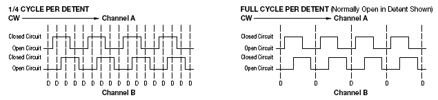
Hi all, I need to replace a rotary encoder in one of my units (Emu Esi-32). Apparently, the one that was in there had a detention scheme as shown on the left hand picture - the one I have here for replacement has the right-hand detention scheme. As a result, when I use the new encoder the entered values are incremented in jumps of 4. What's the easiest way of making my encoder work as it is supposed to? Is there any IC that does this job readily (counter/comparator maybe?), or should I use one of those small PICs to convert the data? Any suggestions are welcome! Thanks, ilmenator

-
Looks like we all miss this opportunity because we do not get any logins. What a pity. All those nice projects...
-
I want some... hopefully registering is fast, otherwise I will probably miss the train... Hey stryd, I'm also using that desk. It is NOT BAD at all, I know a guy who is doing all the measurements for a German Pro Equipment magazine, and the DDX has quite impressive specs (and measures accordingly). Best, ilmenator
-
Hi Sebo, just for the record: which broken solder joint (where in the circuit) caused that specific behavior? Best regards, ilmenator
-
Well, you can have the components that you need for an MBHP project all assembled in a case with a backlit LCD, two encoders with integrated buttons, one analog pot, and five buttons for menu structure purposes (or whatever), plus the power supply for cheap. Now go calculate what you would spend on parts alone to build this thing... Of course, if you are into hardware, soldering, making your own boards and case, then this is probably not for you. But if you are more into software, then this is a simple way around the "how to build my hardware" problem - at least potentially, as the proof of concept is still missing ;). It is not tried yet - but I do have sources which make me believe it should not be a great effort to make MIOS run on these units. ;D Best regards, ilmenator
-
Hello Mike, you might want to look here here or here. Apparently, he is always selling two at a time at ebay, he seems to have a larger stock. Best regards, ilmenator
-
Hello everybody, WARNING: this is not really about a new MIDIbox project already under way, but it might come in handy for some of you - I'll explain. Recently I found out that there is one guy at ebay selling MIR MIDI controllers very cheap: around 20,- Euros. If you don't know what a MIR controller is, look here: http://www.mircontrol.com/ Well, I bought me one, but the setup is really really difficult. It comes with windows software, but still... I have been doing MIDIboxes for a number of years now, so that concept of setting up things is more familiar to me ;). Out of curiosity I opened the MIR - to find out that there is a PIC16F877 inside. So.... it should be possible to get MIOS running on that thingy and make it a 'real' controller, but with the design and case that is really cute and practical. Right now I have no time to actually try this out, but in summer I will do a number of experiments and see what needs to be changed to get MIOS running on this little machine. I'm rather confident that the changes will be minimal. So, grab those MIRs from ebay while you can ;D (No, I am not affiliated in any way with the seller... 8)) There is even some battery-buffered SRAM (HY628100B) on that thing! Plus two encoders with button, plus one analog pot! Best regards, ilmenator mir_1.JPG mir_2.JPG mir_3.JPG mir_4.JPG
-
Look here: http://www.midibox.org/dokuwiki/doku.php?id=midibox_sequencer_vx Best regards, ilmenator
-
Well, I guess chances are that it is not really feasible for Smash to provide a complete kit with all SIDs. But the PCB alone is something I would be very interested in, too! Best regards, ilmenator
-
For each GLCD you will need one PIC. See e.g. the MIDIbox UC in the Wiki. http://www.midibox.org/dokuwiki/doku.php?id=midibox_uc Best regards, ilmenator
-
You already have that with the Bankstick. It's even implemented in MIOS - so why go CAN anyway? Alternatively you can address memory via an 8-bit port - via the same pins that the LCD uses - but both can be connected in parallel. Regards, ilmenator
-
"Wuerden Sie den Artikel nach Irland versenden? Vielen Dank, Mark" Best regards, ilmenator
-
Weiß jemand, wo die transparenten Tastkappen herkommen? ilmenator
-
Mit ner MIDIbox kannst du dieselben MIDI-Befehle senden wie mit einer Doepfer-Kiste... was meinst du mit Kompatibilität? Grüße, ilmenator
-
Hi, on the page you named you need to click on the Download button next to the [tt]Java Runtime Environment (JRE) 5.0 Update 9 The J2SE Runtime Environment (JRE) allows end-users to run Java applications. Installation Instructions | ReadMe | ReleaseNotes | Sun License | Third Party Licenses [/tt] section, then a new window pops open which asks you to agree to the license agreement. Tick the box and you can now download the file that you need - e.g. the offline installation file for Windows, 15.74 MB in size. Best regards, ilmenator
-
Warum nicht gleich die Beschriftung importieren? HPGL Druckertreiber sollten sich im Netz zuhauf finden lassen. ilmenator
-
It might be a regulator: you could check what type of SRAM voltage (5V, 3V) you have on your memory expansion. Best regards, ilmenator
-
http://cgi.ebay.de/ws/eBayISAPI.dll?ViewItem&item=270056780421&ssPageName=ADME:B:SS:DE:1 This is a 240 x 64 display for a reasonable buy-it-now price, interesting for people in Germany. I have bought these displays from that guy before, they are used in the MIDIbox UC (Universal Control) (formerly introduced as MIDIbox GLCD in this thread: http://www.midibox.org/forum/index.php?topic=7724.msg52685#msg52685 Best regards, ilmenator
-
J5 / A7 (RE2) as "status input pin" problem - solved
ilmenator replied to ilmenator's topic in Testing/Troubleshooting
That's exactly how I will implement this. ;D Best regards, ilmenator -
J5 / A7 (RE2) as "status input pin" problem - solved
ilmenator replied to ilmenator's topic in Testing/Troubleshooting
Stryd, thanks for offering help - I will surely get back to you one of these days. My application is not time critical, so I think I could establish a protocol that insures that only one device accesses the bus at a time. In the original machine that I am trying to "hijack" this is done via the Card Status flag - so the synth (you might be able to guess what I am trying to do by now ;D) only accesses the buses when a card is present. If I simulate that status flag with my application, I should be able to prevent the synth from accessing the bus. I will further try to physically remove the buses from the synth via the 646 to minimize the risk of damage to the synth. Whenever the status flag is set by my application, it means it will no longer have control over the buses, but the synth takes over. There is one critical moment, that is when my application wants to get back the bus control. It needs to set the status flag accordingly, which should not be done when the synth is trying to write to the card. But on the other hand, you would not unplug the card physically from the synth when you know that the synth is writing your sounds to the card, either, or would you? ;D Best regards, ilmenator -
Yes, that's the one! Best, ilmenator
-
J5 / A7 (RE2) as "status input pin" problem - solved
ilmenator replied to ilmenator's topic in Testing/Troubleshooting
I have some more mysteries to solve before going public with this baby... One is best formulated in a question: what happens if I "hijack" the address and data bus of a device that is supposed to be the master of these buses with only one "receiver" attached? Do I need to separate the original master from the buses whenever the "hijacker" tries to access it? More specifically: will a second "bus master device" (i.e. a PIC using address and data bus for communication with SRAM memory) present any harm to the first one? I have a feeling that I do not want to try this out... So I have looked into the 74HCT646 bus transceiver to act as a bus separator. I know that there are special bus switch devices like e.g. Fairchild or IDT 3245 bus switches, but I have not found a way of purchasing them in lower quantities here in Germany. Has anybody used the 74HCT646 before? Best regards, ilmenator -
Hi John, somewhere on the net I have seen a page from a guy who uses Banksticks instead of Q-Cards for storing sounds for his Waldorf Q. As far as I know, the Q-Cards are "normal" flash cards with a pinout identical to those telephone or health insurance cards we have in large parts of Europe. So maybe if you use one of those card readers you can read a Bankstick? Best regards, ilmenator
-
J5 / A7 (RE2) as "status input pin" problem - solved
ilmenator replied to ilmenator's topic in Testing/Troubleshooting
Hi Thorsten, I replaced app_flags.SRAM_CARD_STATUS = PORTEbits.RE2; with if( PORTEbits.RE2 ){ app_flags.SRAM_CARD_STATUS = 1; }else{ app_flags.SRAM_CARD_STATUS = 0; } , now everything works as expected. ;D I left a comment in the C programming section of the Wiki: http://www.midibox.org/dokuwiki/doku.php?id=c_tips_and_tricks_for_pic_programming#sdcc_bugs_workarounds As always Thorsten: thanks for that hint! Best regards, ilmenator -
J5 / A7 (RE2) as "status input pin" problem - solved
ilmenator replied to ilmenator's topic in Testing/Troubleshooting
Yes, the corrected version does its job as it's supposed to. :D So what I have now is the correct potential on the input pin RE2 of the PIC. Still I cannot read the status with my code. Here is what I do: ///////////////////////////////////////////////////////////////////////////// // This function is called after startup to initialize the SRAM ///////////////////////////////////////////////////////////////////////////// void SRAM_Init(void) __wparam { // clear PortE PORTE = 0x00; // disable the ADC which allocates the analog pins // only needed if controls pins are connected to port A ADCON1 = 0x07; ... // put PortE in output mode // Pin RE.0 = output TRISEbits.TRISE0 = 0; // Pin RE.1 = output TRISEbits.TRISE1 = 0; // configure RE2 as input for reading SRAM card status // Pin RE.2 = input TRISEbits.TRISE2 = 1; return; } Then in main.h I modified the Global Types section like this: ///////////////////////////////////////////////////////////////////////////// // Global Types ///////////////////////////////////////////////////////////////////////////// // status of application typedef union { struct { unsigned ALL:8; }; struct { unsigned DISPLAY_UPDATE_REQ:1; // requests a display update unsigned SRAM_CARD_STATUS:1; // if set, SRAM card is present }; } app_flags_t; In main.c I used the Tick() function to check the status and request a display update - I know that the display update should not be requested from here, but it's a quick and dirty solution. ///////////////////////////////////////////////////////////////////////////// // This function is called by MIOS in the mainloop when nothing else is to do ///////////////////////////////////////////////////////////////////////////// void Tick(void) __wparam { app_flags.SRAM_CARD_STATUS = PORTEbits.RE2; app_flags.DISPLAY_UPDATE_REQ = 1; } Finally, in DISPLAY_Tick() I print the status on the LCD like this: ///////////////////////////////////////////////////////////////////////////// // This function is called in the mainloop when no temporary message is shown // on screen. Print the realtime messages here ///////////////////////////////////////////////////////////////////////////// void DISPLAY_Tick(void) __wparam { if( !app_flags.DISPLAY_UPDATE_REQ ) return; // clear request app_flags.DISPLAY_UPDATE_REQ = 0; if( app_flags.SRAM_CARD_STATUS ){ MIOS_LCD_CursorSet(0x60); MIOS_LCD_PrintCString("Card OK"); } else{ MIOS_LCD_CursorSet(0x60); MIOS_LCD_PrintCString("No Card"); } } I think that this code should work - any thoughts on this? Thanks very much, ilmenator