bugfight
-
Posts
812 -
Joined
-
Last visited
Content Type
Profiles
Forums
Blogs
Gallery
Everything posted by bugfight
-
even with 7912, you will need -14v at the input instead of +14...
-
 run the SRIO interconnection test. if you still get 4.4v on SO, then you might have a bad pic. If so, you might be able to restore it, but someone else will have to help there (SmashTV?), I don't remember the voodoo required...
 -
won't work. you will get nothing at -12 with this design. you might even let the magic smoke out of that regulator.
-
this hex is for slave sid cores only
-
i noticed this bug in mios studio as well (under windows) i used midi-ox instead. any program or hardware that can send mod wheel will work...
-
Midibox Of The Week: Sink fled after hearing MBSIDV2 by SounDuke
bugfight replied to SounDuke's topic in MIDIbox of the Week
congrats duke, looks fantastic! -
hmmm another builder drills the corners. maybe something to consider if another run of panels is done..
-
very nice stuff!
-
wooohoooooo!
-
i like showing 132 in binary with my fingers... *whack*
-
in more ways than one... *whack* congrats on the round number!
-
gatelength 0 - is that no gate or a very short trigger?
bugfight replied to jrp's topic in MIDIbox SEQ
i saw an interesting site about diy player pianos the other day. had info on solenoids and using velocity to control strike. i can find it again if you are interested... -
it's the Crystalfontz CFAH2004A-YTI-JP the one from altitude's bulk order: akkk, i just realized i didn't pull off the protective film, so it looks even better than that photo) edit* fixed linky
-
hehe i watched this almost every day for weeks
-
you can't hear it? i'll turn it up to 11 then... when i have something that's not just me wanking with presets, i'll post it. green good! napster bad!
-
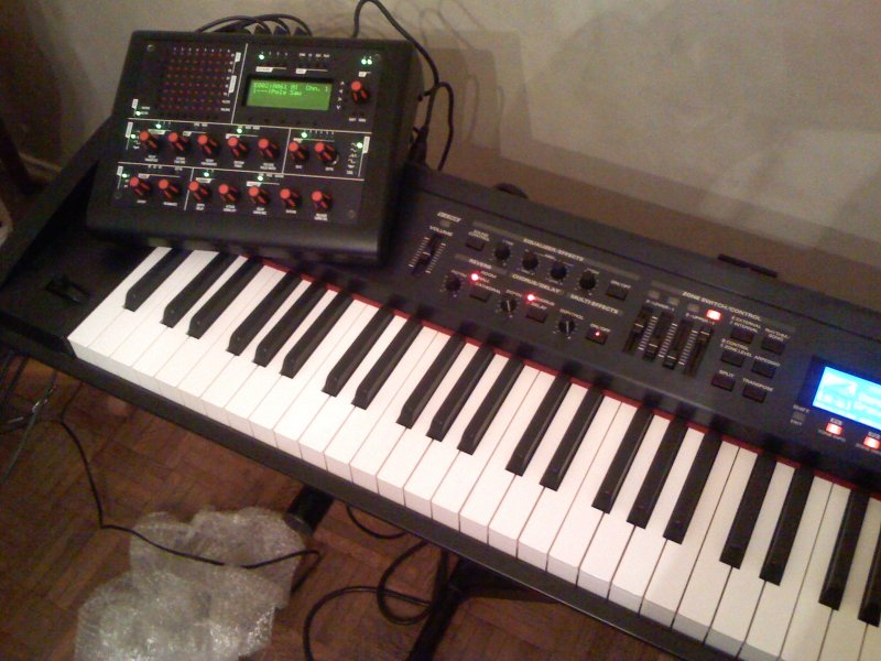
on top of old smokey...

-
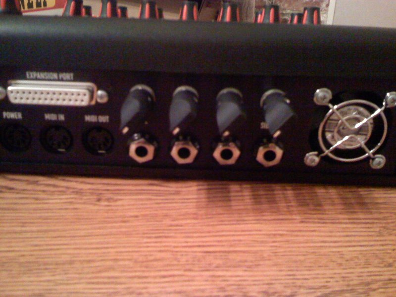
here's the back. i used neutrik audio jacks with the internal thread, which looks pretty good, i think. the feedback pots i used were 100k instead of 500k which works fine. i mounted the expansion port but nothing is connected to it yet (soon to be Seppoman's ssm filters and who knows what else?) the fan makes some noise so i'm gonna think about what to do about that after i play with it some more.

-
meter rocking! way cool, tk!

-
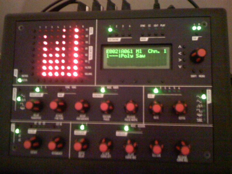
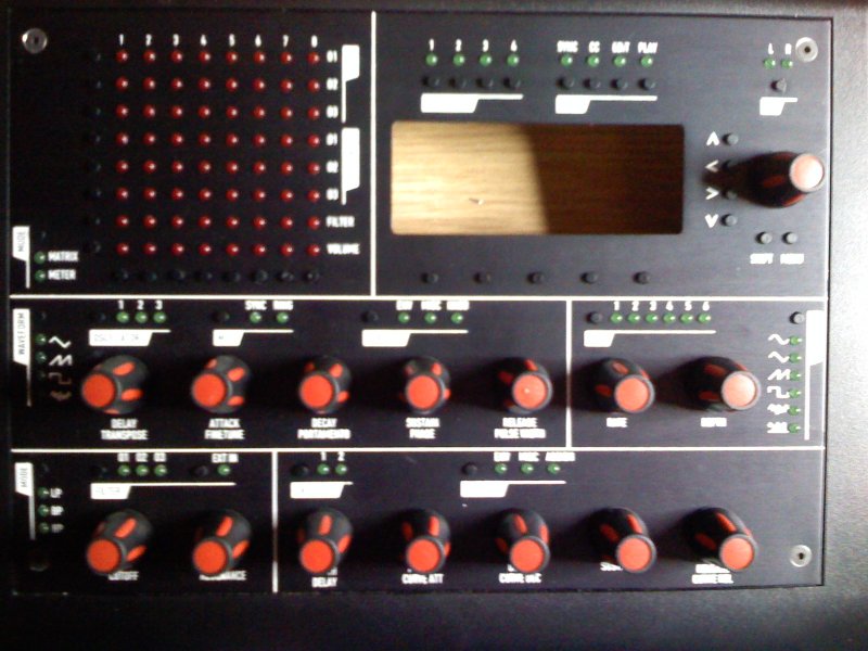
all done, everything mounted open to show gory details

-
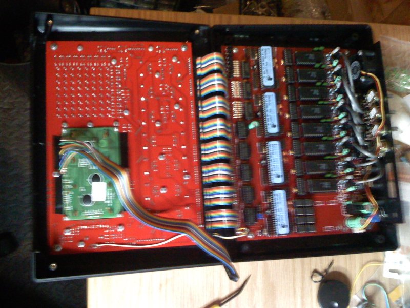
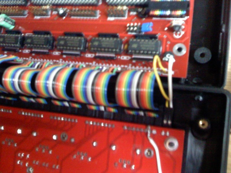
ribbons connected. you can see one of my pcb repairs too (the white wire on the control pcb)

-
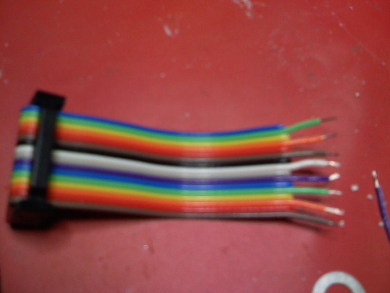
i used press on DIL connectors like SmashTV sells. this is not only way easier than crimping all those SIL pins, but also is a shorter connector and has strain relief. note that i only use one row of the connector and thus solder every other cable line. i shoved the 90 degree sil connectors down all the way when i soldered them which allowed me to use the top row, but it might be just fine to leave them at the original height and use the bottom row... i did use a two pin SIL connector for the power and ground pins.

-
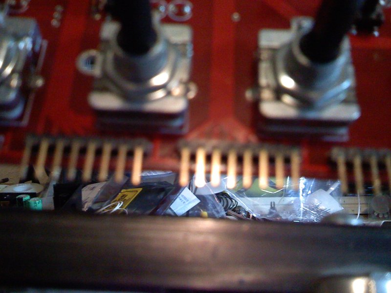
i used 90 degree SIL headers instead of soldering ribbon directly to the control panel. this saved my ass big time, when i had to trace down a short (turned out to be caused by the lcd mount, so trim those leads behind the LCD!) and also what turned out to be several damaged traces on the brd, which are thin, so i just did end runs around them (soldering a wire between the two nearest pads) all i had to do was unplug the panel and trace away. Wilba pointed out a great idea for tracing the LEDs: with panel disconnected you can use a 5v line with 1k resistor to trace all the LEDs, just ground each of the 8 pins where the transistors would go in turn and touch each other DOUT line with 5v through the resistor.

-
ok some photos, to be annotated later: just pointing out things i did a bit different than friend wilba. forgive me for this red-headed step child *whack* notice the drilled and countersunk corner screws. i tried 3 times to jb-weld this, each time i could pull them off with my fingers.

-
A full-blown newb on the way to a POKEY synth
bugfight replied to nILS's topic in MIDIbox User Projects
you should make the serial io headers match smashtv brds so cabling will be simple... -
another kicking demo. thanks again again, tk.