Wilba
-
Posts
3,310 -
Joined
-
Last visited
-
Days Won
2
Content Type
Profiles
Forums
Blogs
Gallery
Everything posted by Wilba
-
I looked at a lot of datasheets to come up with the right size for the cutout on the PCB... obviously didn't come across that one. :( Good plan. Unfortunately, taking a Dremel to your PCB voids the warranty. You have been warned. :)
-
Oops! I forgot you already did this, bugfight... Nothing more to do here, moving along.... :)
-
You can get Front Panel Express or Schaeffer to cut a 3mm piece of acrylic with a routed edge 1.5mm deep, so it fits inside the panel hole. To do this you would look at the dimensions of the cutout in the MB-6582 panel FPD file and create a new FPD for 3mm acrylic window which is this size plus 3mm all around. Then add a "Rectangle in rectangle" cavity, with the outer rectangle bigger than the piece (so it routes a clean edge) and the inner rectangle with the same dimensions as the cutout less some error tolerance (i.e. take off 0.5mm perhaps). I've done this with the MB-SEQ - it's a 3mm panel with a 3mm window, and I route both the back of the panel and the window with a 1.5mm edge so they fit together flush on both sides. I probably should design it myself in FPD and make the file available.
-
That should be fine then. There is clearance to the top of the ICs, the caps are shorter, so it's OK.
-
Maybe. Check if it is taller than an IC+socket. If it's shorter than IC+socket height, then you don't have to change it. If it's taller than IC+socket height, then it might be too close to the CS PCB. I'm sorry I can't give a better answer - I would have to disassemble my MB-6582 to measure the actual height above PCB - I only know that there is clearance for the IC+socket and maybe an additional 1mm. (FYI I knew it would be close before I built the prototype and fully anticipated using low-profile IC sockets or *shock* *horror* soldering the 74HC165 to the PCB if neccessary). If you are using this capacitor size here, where else are you using it? What about the capacitors inside IC sockets, and in the audio buffer above the SID ICs? All the capacitors I use are either small ceramic (<100nF), monolithic (>=100nF) or electrolytic (>=1uF)... (ok and some nice 22nF SID filter caps).
-
Can you send a link to where you bought the LCD, or upload a datasheet? Do the mount hole positions match the holes on the CS PCB? To answer your question, you can enlarge the cutout with a Dremel up to the pads of the switches, which would be ~2.5mm from top and ~3mm from bottom. I use a "grinding disc" to cut PCBs, and cut with the edge.
-
It looks almost as good with just a roughly cut piece of 3mm acrylic between the LCD and panel, i.e. it doesn't have to be perfectly cut to fit the hole. On the last one I made (see pics in wiki), the acrylic was cut to the same size as the LCD bezel, then attached to the panel with superglue.
-
ALSO those capacitors look very big! If you intend to use the MB-6582 control surface PCB in a PT-10 case, the lower edge of the control surface PCB gets very close to the IC's U20,U19,U18,U17,U16. Those capacitors cannot be much taller than the IC+socket. (I expected people would use small monolithic ceramic capacitors here, as shown in the parts list). Also they make taking out the ICs harder, not that you would need to I suppose.
-
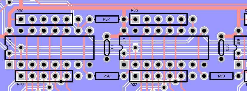
If using a 6-pin resistor network in R38,R36,R34,R32,R30, the 6th pin (the pin not inside the white box) serves as 10K pullup which would make R57,R58,R59,R60,R61 redundant. The exact substitution list is: 6th pin in R38 => R57 6th pin in R36 => R58 6th pin in R34 => R59 6th pin in R32 => R60 6th pin in R30 => R61 You might be getting confused because of the placements.... it's actually the 6th pin in R36 which is connected to U19 pin 10, U20 pin 9 and R58.... and the 6th pins of R39,R37,R35,R33,R31 are not being used.
-
meaning "we copied the crêpes recipe from the French, but couldn't get it right so we just called it pancakes". What next... shall we debate the differences between jellies, jams and conserves? ;)
-
What a lot of crêpes! That's not a pancake!
-
Mmmmm pancakes...
-
Some interesting statistics... SIDs sold per country from MEGASALE #2 to MEGASALE #7 Country Qty % USA 732 29.55% AUSTRALIA 296 11.95% GERMANY 268 10.82% FRANCE 245 9.89% CANADA 211 8.52% UK 183 7.39% SWEDEN 91 3.67% NETHERLANDS 72 2.91% NORWAY 44 1.78% FINLAND 40 1.61% DENMARK 38 1.53% ITALY 34 1.37% AUSTRIA 28 1.13% BELGIUM 26 1.05% SPAIN 23 0.93% ISRAEL 21 0.85% POLAND 20 0.81% HONGKONG 16 0.65% JAPAN 16 0.65% SINGAPORE 10 0.40% SLOVAKIA 10 0.40% CZECHREPUBLIC 8 0.32% MEXICO 8 0.32% IRELAND 6 0.24% SERBIA 6 0.24% PERU 5 0.20% BRAZIL 4 0.16% NEWZEALAND 4 0.16% RUSSIA 4 0.16% SWITZERLAND 4 0.16% THAILAND 2 0.08% UKRAINE 2 0.08% Total 2477 100% [/code] Australia is second, but only has a population of 21 million, compared to USA 303 million, Germany 82 million, France 61 million, Canada 33 million, UK 60 million. :P
-
... NO CASH? WANT TO GET SOME LATER? Just email me with a "pre-order" for a future MEGASALE, so I can email you later. I call it a "pre-order" but it's really just me notifying you that I will have more to sell soon and letting you make a real order then. You can cancel at any time. Just follow the link: http://www.midibox.org/dokuwiki/wilba_6582a_sid_mega_sale
-
Don't stress... FPE do excellent work and have excellent customer service.
-
I always avoid desoldering whenever possible. If you absolutely must desolder a part from a PCB and don't need to keep it, cut it on the component side so you can desolder one lead at a time. Sometimes desoldering might involve adding more solder to heat up the entire joint so you can pull the lead out from the component side, and then using a solder sucker (desoldering pump) to suck out the solder from the joint. You just do not want to rip the pads off the PCB, as fixing this is really annoying. Of course if you're desoldering something you want to keep from a PCB you'll never use again, then you can be brutal and repeatedly heat joints and wiggle a part out of the holes.
-
*** THIS MEGASALE IS CLOSED *** MEGA-SALE #8 will happen in late January. There is no waiting list. Email your order directly to me. THE GOODS 6582 (6582A) SIDs are just like 8580 SIDs and not like 6581 SIDs. They have the filter that works best for the MB-SID V2 Bassline mode, low noise, less bugs. Look elsewhere for whether 6582/8580 is better/worse than 6581. I use eight of them in my MB-6582 MB-SID V2 Synth, but you already knew that. THE DEAL 6582 SIDs now cost AU$30 each plus postage and handling fees. I add up the exact cost of SIDs and postage in Australian dollars, and then multiply by 1.0351966873706 to add the handling fee. Postage will be calculated as the actual cost to post, plus packaging. The PayPal invoice will include the handling fee in the postage amount. Most of the time, postage will be AU$6.15 for an airmail letter. If you are ordering more than 8 SIDs, I might choose to upgrade the postage to an insured parcel, where available. All SIDs I sell are tested before packing to ensure the oscillators and filter work. These chips are new-old-stock, not pulls from Commodore 64, and are unused when sold, with absolutely no long term guarantee. However, considering these chips have been safely tucked away in antstatic tubes for 15 years, they are less likely to fail than one you find in Commodore 64 that has been power cycled thousands of times and been alternately cooked and frozen in a garage etc. From my experience, after testing over two thousand 6582 SIDs, only 3 were found dead. After salvaging about eight 6581s, all were found to have dead filters or dead oscillators. If you find any chips faulty through initial testing with hardware that is known to work, I might allow you to return them and get a refund or replacement if possible. HOW TO ORDER Just follow the link: http://www.midibox.org/dokuwiki/wilba_6582a_sid_mega_sale NO CASH? WANT TO GET SOME LATER? Just email me with a "pre-order" for a future MEGASALE, so I can email you later. I call it a "pre-order" but it's really just me notifying you that I will have more to sell soon and letting you make a real order then. You can cancel at any time. Just follow the link: http://www.midibox.org/dokuwiki/wilba_6582a_sid_mega_sale
-
You don't need to mount the nuts on the encoders.
-
13 6581 SID chips for sale - all tested on a MIDIBOX SID
Wilba replied to stevel's topic in Fleamarket
If I wanted to play lucky dip, I'd just buy a used C64. If I'm paying US$40 for a SID, I would demand to have a choice of which revision/datecode I got, because the filters are not identical. You could end up with an R4AR and be happy, or some R1 with a pissweak filter. In addition, US$83.66 for postage to Australia! WTF? <free publicity>WILBA'S 6582A SID MEGA SALE #9 STARTING SOON ~US$20 per SID, new unused SIDs, fully tested, each was tested and sounds identical because they're not noisy, unpredictable 6581 SIDs...</free publicity> -
In a previous post, I said Doug Wellington would sell his spare SSM2044 to the people in the U.S. since he conveniently has enough, thus I only bought/sold enough SSM2044 for people everywhere else. I assumed Doug would have emailed y'all, but he must have been distracted by having his marrow sucked out.
-
It might make it easier to use for the MB-6582 PCB, because you could use a PCB-mount 7-pin DIN socket, and then make some changes to the board, like bridge across the bridge rectifier pins. My previous suggestion was to add a DIN plug to the existing C128 PSU cable. For your idea, you can buy just the DIN plug and use whatever cable you like. The DIN plug/socket can certainly handle 2 amp loads.
-
The rule of thumb about regulators is, if you can't keep your finger on it, it needs a heatsink. The one in my MB-6582 gets warm, but not hot.
-
I suggest using a 7-pin DIN plug and matching panel mount socket - these are fairly easy to find (it's only the PCB-mounted 7-pin DIN socket that is hard to find). Then wire it like a normal C64 PSU plug - that way you can be sort of compatible if you need to change PSUs later. Plus I think XLR plugs/sockets are much more expensive. But it's just a suggestion - there's nothing wrong with your idea. I don't think so. I would assume this PSU is much like the C64 one - the transformer has two 9V AC secondary coils, one is rectified and regulated to 5V, the other goes straight to the plug, which can then be rectified and regulated on the MB-6582 PCB. You should have no trouble connecting this to the J1A header, but I would advise using a polarized header and connector so you never accidentally swap 5V/ground.
-
Cool! Congratulations!