Wilba
-
Posts
3,310 -
Joined
-
Last visited
-
Days Won
2
Content Type
Profiles
Forums
Blogs
Gallery
Everything posted by Wilba
-
That would be bad. You would be joining audio outputs together, which is bad. Audio outputs go up and down in voltage, and if one was higher than the other, current would flow from the higher one into the lower one. The point of the dual gang is to keep them separate and maintain the stereo signals, not mix them to mono. Since you have some dual gang pots already (just too big), wire up one anyway and have a play with it. Then you'll realise that "all on" is mostly useless, and that there'll be a nice sweet spot on the pot that gives a nice resonance boost at res=230 and self-osc. squeal at 255. Keep in mind that it's not just one resistor value - the pot is being used as a voltage divider, so that you get between 0% and 100% of SID output fed back into input... that's why the pot "ends" are connected to SID output and ground, so the "wiper" can be anything between (0%=ground, 100%=SID output). If you continue on the switch idea, then you can use any trimmer pot inside the case (wired the same way as the dual gang feedback pots, i.e. voltage dividing!) and a DPDT switch on the SID input that can switch between the pot wipers and ground.
-
You use pots to control how much feedback to use. When you enable Ext In (i.e. filtering the external input, and thus filtering the output fed back into the input), and of course band pass, you can get a resonance boost or a full blown self-oscillating squeal. You could in theory choose the right amount of feedback using a pair of trimmer pots and just an external switch to turn on/off feedback. If finding these pots is proving difficult for a lot of people, I can find a good bulk source somewhere and buy a bunch...
-
Keep your SSM boards, I'll post you some 4620 for free... they probably have the EUSART bug (i.e. requires IIC_MIDI module). This gives me more motivation (i.e. a kick up the ass) to send you that C64 power switch as promised :)
-
How many voices does the MB-6582 have in Poly Mode?
Wilba replied to Futureman's topic in MIDIbox SID
Yeah it's four stereo voices, but since each "voice" is a pair of SIDs, and each SID has three oscillators, so that's six oscillators that could be detuned or octave shifted... I'm not saying that more wouldn't be nice, but you can get some pretty fat sound with "only" four. :) No difficulties, it works fine. You just have to remember to select all SID engines (that are in SPV mode) when you change patch. Hardware limitiation - TK's already squeezed as much as he can out of an 8-bit PIC. Maybe MB-SID V3 on a new microcontroller will have 8 voices... start praying now. :) -
How many voices does the MB-6582 have in Poly Mode?
Wilba replied to Futureman's topic in MIDIbox SID
It's in the manual: -
Someone didn't RTFM.... ;D
-
cool ;D
-
Why doesn't anyone post pictures? :(
-
The FPD files for the panels are here: http://www.midibox.org/dokuwiki/wilba_mb_6582_panels There are pictures elsewhere on the forum, just search for "MB-6582 panel". The new buttons are documented in the MB-SID V2 manual, or are fairly self-explanatory - just press them and see what happens!
-
The other thing you need to work out is how to merge MIDI Out of the keyboard with other MIDI Out (i.e. from sequencer, PC) into the MB-SID MIDI In. So you may need another Core, or at the very least, an IIC_MIDI module to connect MIDI keyboard, and then modify the MB-SID application to accept MIDI In from the IIC_MIDI's MIDI In.
-
Ahh you mean a keyboard? You can use another Core module with DIN modules to be a MIDI keyboard, and then connect this to the Core which runs the MB-SID application.
-
yes. 1. Unscrew screws of your MIDIbox case. 2. Put keys in MIDIbox. 3. Screw screws of your MIDIbox case.
-
The M-Audio Delta 1010LT does this, although it's DB44 and a bucketload of connectors.
-
I should probably post a warning in the parts list about this. Can you tell me where you got your "wrong" sockets (link if possible, or site/part number) and I'll mention not to get them. :) Maybe also take photos from above and below to show what to do to fix the problem.
-
The 1st problem was with the first Core. He's swapped PICs 1 and 2 and the 1st problem is gone. Hooray. The PIC that used to be in Core 1 has (apparently) got some issues with uploading. Maybe it's the PIC, maybe it's because he's trying to upload in Core 2, which has a problem which might be related to the right SID not working. But obviously to know that the right SID is not working, he must have a working PIC in Core 2. So he might have two NEW problems, the order he wants to fix them is up to him. Stop being a troubleshooting Nazi. Oops, Godwin's Law, you better lock this thread too, you forum moderator Nazi. Oops.
-
No, the required DIN and DOUT are on the PCB. You connect the PCB directly to a core or ultracore through J8/J9. It's probably possible, but not designed. The case was designed to be compact, and not accommodate large transformers. i.e. I'm sort of catering for two scenarios - people who want a compact desktop case (or a rack mounted case but don't want any "extras" like CV outputs), and people who want a big 3U rack case stuffed with a mains-powered bipolar PSU and an AOUT module. There is a third scenario - a desktop/rack mounted case with external bipolar PSU and an internal AOUT... but I haven't really thought about it much. One of the cool things about Doug's case design is the I/O panel has an L-shaped cross-section, which you can modify yourself - if you think you can squeeze a transformer (or even a switch mode PSU) inside the case, go for it, add another hole for a mains socket. But you have to know what you are doing, I can't help you with that.
-
Yes.
-
Yes. I'm preparing a parts guide now: http://www.midibox.org/dokuwiki/wilba_mb_seq_parts_guide
-
Run the testtone application on Core 2. This should prove it's not the MB-SID app at fault. Since you say both SIDs are working, it's probably a hardware fault... perhaps bad solder joint somewhere, or maybe even the audio output buffer.
-
It's hard to say when... I still have a 2nd SSM2044 bulk order to do (approx. 400 chips) which was delayed for a while, then another 6582A SID MEGASALE #7 which might happen before I do this SEQ PCB and parts bulk order. If it was just the PCBs, that would be easy, I'd get everyone to pay in US$ and I'd have a pile of cash in PayPal that I'd transfer to the PCB manufacturer... I also have a good idea how much postage would cost so could precalculate a single payment from everyone. Parts, however, complicate things immensely... e.g. I don't know shipping costs of 3654 switches and caps.... :) I have a lot of accounting to do before I start collecting money from people.
-
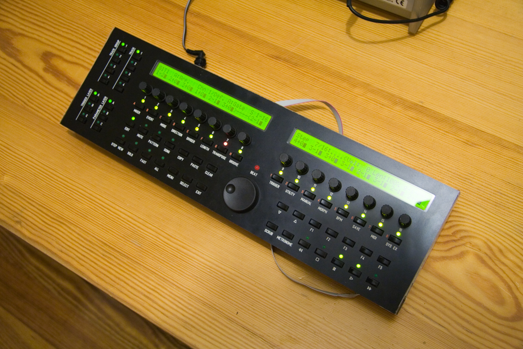
Poor quality photograph of the MB-SEQ assembled, still without case, I'm using some corrugated cardboard on the sides and back. This is about as finished as I can make it without getting one of Doug's cases ;) but I think enough for people to decide if they want to build their own, so if you want PCBs, jump on the bulk order forming here: http://www.midibox.org/dokuwiki/wilba_mb_seq_pcb_bulk_order that number again, 1800 WILBASEQ don't delay! eternal happiness is just a dollar away!
-
1. The "Sync" LED isn't connected to anything yet. If you really want to test it, try the test app I uploaded here: http://www.midibox.org/forum/index.php/topic,10390.msg78577.html#msg78577 2. This could be the switch or the diode or a bad solder joint. Since you say you are seeing LEDs lit in that row, then it seems to make sense that the switch isn't being sensed. Here's a good test to prove it. Edit setup_mb6582.asm and swap the SR/pin numbers for those two buttons: i.e. the original: DIN_ENTRY CS_MENU_BUTTON_M_O1Ptch, 16+7, 0 DIN_ENTRY CS_MENU_BUTTON_M_O2Ptch, 16+7, 1 [/code] swap just the 0 and 1 at the end of the line. Now the "O1 Pitch" button and "O2 Pitch" buttons are swapped. The "O2 Pitch" button should light up the top row, thus proving the LEDs are all fine. The "O1 Pitch" button should light up the 2nd row if it was working, and since we're trying to prove it's really the switch at fault, it should not light up the 2nd row. After that, swap the 0 and 1 around, rebuild and upload the app. Check "O1 Pitch" button is still the problem. Now you can try shorting with a piece of wire to try and make that switch work. This might be tricky to do because you're watching for the flashing row while tinkering on the bottom of the board. Maybe use a mirror or something. Refer to the PDF of the PCB layout. Try shorting just the switch, i.e. between a pin at the top to a pin at the bottom. If it works, the switch is the fault. If it doesn't, it could be the diode. Short between a bottom pin of the switch and the bottom pin of the diode (looking at the bottom of the PCB, the two pads right of the switch's four pads is the diode, the bottom pin has a track going down from it, connecting the bottom pins of the other diodes for that column of switches). If shorting to the diode pin works, maybe the diode was put in the wrong way, or it's dead and not conducting at all... try testing it conducts top to bottom, or take off the panel and inspect it, desolder it etc.
-
So you now have a PIC which has problems? Try the change_id app with that PIC, make it device ID 2, and put it in Core 2, upload the MB-SID app to that PIC again. See if it works happily in Core 2. If it doesn't, the PIC is at fault somehow. If it works fine, then it's just one of those weird things that happens... you've swapped PICs so in theory the original PIC 1 should not "just work" in Core 2.... Sometimes you tinker with stuff and they just work again without really knowing why. Don't question it further, just thank the MIDIbox Gods and start jamming.
-
No... to get the passive mixer/headphone connection working, you'll need to do some track cutting and different wiring. The "quick fix" I suggest will get it working and you can do a better solution later, just remember to take out those resistors!
-
OK they are definitely different, the contacts with the plug go out to the opposite side to the "right" sockets. The "quick fix": Take out the two 10K resistors just below each socket. These are used to mix each channel with the others when there is no plug in the socket. It's no great loss. Carefully solder some insulated wire between the three pairs of pins, i.e. the wires will be bridging between the left and right sides of the socket. Do this for all four sockets. Now you should have sound coming out the right socket!