Wilba
-
Posts
3,310 -
Joined
-
Last visited
-
Days Won
2
Content Type
Profiles
Forums
Blogs
Gallery
Everything posted by Wilba
-
** THIS SALE IS CLOSED ** 6582 SID MEGA-SALE #7 6582 SID MEGA-SALE #1: 200 SIDs 6582 SID MEGA-SALE #2: 312 SIDs 6582 SID MEGA-SALE #3: 512 SIDs 6582 SID MEGA-SALE #4: 312 SIDs 6582 SID MEGA-SALE #5: 546 SIDs 6582 SID MEGA-SALE #6: 624 SIDs I'm up to MEGA-SALE #7! Insane! They'll run out eventually... ;D This MEGA-SALE will run in October/November, assuming there's enough pre-orders. Add or check your pre-order on the list here: http://www.midibox.org/dokuwiki/wilba_6582a_sid_mega_sale The general process: You add your name to the pre-order list I will contact you by PM or email and request you to send an order with your address and PayPal details I send a PayPal invoice by email You pay the PayPal invoice I test, pack and post your SIDs Do not email or PM me orders now! This is just an announcement/reminder/pimpage of the MEGA-SALE #7, so there are a good number of pre-orders by the time I'm ready to run the sale in November/December. THE GOODS 6582 (6582A) SIDs are just like 8580 SIDs and not like 6581 SIDs. They have the filter that works best for the MB-SID V2 Bassline mode, low noise, less bugs. Look elsewhere for whether 6582/8580 is better/worse than 6581. I use eight of them in my MB-6582 MB-SID V2 Synth: http://www.midibox.org/dokuwiki/wilba_mb_6582 (but you already knew that) THE DEAL 6582 SIDs cost AU$25 each plus postage and handling fees. I add up the exact cost of SIDs and postage in Australian dollars, and then multiply by 1.0351966873706 to add the handling fee. This means 6582 SIDs cost approximately AU$25.88 or US$21.72 or 14.77 EUR when including handling fees (actual exchange rate used by PayPal will be different). Postage will be calculated as the actual cost to post, plus packaging. The PayPal invoice will include the handling fee in the postage amount.
-
Can you post a link to the part from Digi-Key? I'd like to know how the footprint is different. For your trouble, I will post you one that fits for free, send me your address in a PM.
-
It's more than just a design goal, since I'm giving TK the prototype PCB and parts, he has no incentive to make it incompatible with MB-SEQ V4 ;)
-
The "soft" button looks like a standard 12mm x 12mm footprint. If you have a datasheet I can confirm this. The switches I use are from e-switch, because they have the exact size "shaft" to fit the rectangular caps. But other kinds of 12mm x 12mm tactile switches will fit the PCB. I could drop the e-switch TL1240 footprint, and putting in a standard 6mm x 6mm tactile switch footprint (like what I used on MB-6582 and the picture with the "ice cube"). If you want it, then work out dimensions - it has to fit a 10mm gap and 3mm panel. From just looking at the "ice cube", I can tell it's nearly 30mm from base of switch to top of the ice cube. I can't see how that will work with a 10mm gap and 3mm panel. I can make changes to the PCB layout if it's not going to affect the intended components, but I'm not going to do any changes unless it's going to work (it will fit) and someone is definitely going to use it.
-
-
Don't get sucked into bugfight's anti-JB-Weld FUD campaign! To be perfectly clear: When I made the prototype MB-6582, I glued more spacers to the panel than were required because I was pessimistic about the sticking strength of JB-Weld. I then didn't take out mount holes when doing the final PCB design, and then didn't use any less when building MB-6582 units (mine and others), I just put all 23 in there, even though 10 would work just as well. Everyone has had the option of putting less than 23 if they wanted, but now that Doug's going to the trouble of stamping standoffs into the panel, and they might be $1 each, it makes sense to optimise.
-
This switch won't work with this PCB/panel construction. I can add the pads for this switch, but the switch plus cap is 13.2mm. To make this work with a 3mm panel, you'd need to reduce the gap form 10mm to 8mm. That's possible, but then the encoders will stick out an extra 2mm. That's fixable if you use different encoders, but there are no pads for different encoders. Even that is fixable... ;) The "unfixable" thing is the size of the switch base overlaps where the spacers are to go on the PCB. Moving the mount holes for the spacers is hard. It is a shame because I like this switch! I like it so much I'll keep thinking about if it's possible to make it work...
-
-
Yes and yes. The 16 step encoders are mounted above the PCB. The datawheel encoder is mounted below the PCB, through a hole in the PCB (this is done by PCB manufacturer, no drill required). You use the washer and nut that comes with the encoder. If for some reason you didn't get some with encoders from Voti, etc. then I have plenty to spare (as does everyone who bought SoundWell encoders from me when I ran that bulk order). So... making the datawheel encoder lower means the datawheel knob is at the right height for the panel. Of course, I put the same footprint for all encoders, so you could choose to mount the datawheel encoder above the PCB and use another kind of knob. I just mounted the encoders on the prototype board - the SoundWell encoders fit perfectly, however, I needed to trim off the extra "knob" bit of the encoder base. This is easily done with a Dremel, but some wire cutters and strong hands will do the job.
-
Nice switch. This footprint is not on the PCB, only standard 12x12mm tact, e-switch TL1240 and MEC Doug asked me to consider this switch but I think the dimensions don't fit the rest of the design (I think height was the issue). If you find me a datasheet for this switch I can see what is possible and what is not.
-
Doug will sell SSM2044 to the people in the U.S. I will sell SSM2044 to everyone else (or to people in the U.S. if Doug runs out). We both will have the spreadsheet that seppoman used for the boards, so you will be contacted by email (the email address you used for PayPal), or via PM. I have 100pcs already, which I'm posting to the Aussies (conveniently, it's exactly 100 required by Aussies). I will do the "big" order once I get confirmed orders from people, i.e. once people reply to my email, which has not been sent yet so stop nagging.
-
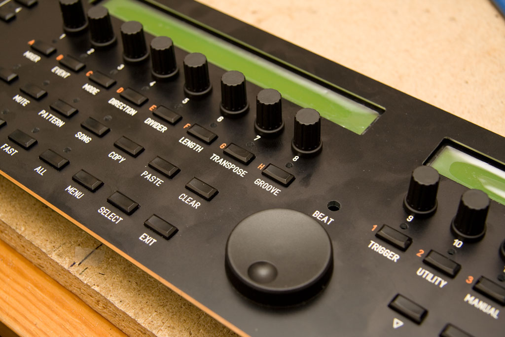
In case people were interested in seeing how the switch caps and knobs look in real life... here's a quick teaser shot after the PCB/panel/components fit test. Knobs are just placed on the panel, no encoders mounted yet, but I did fit test them separately. The panel is from Front Panel Express. Acrylic windows for the displays are not installed into the panel yet.
-
:o that can't be right...
-
This was a bulk order I ran a while ago, basically to get some for the people who bought the first run of PCBs, so nearly all of them went to SmashTV for putting in base parts kits and I sent out a few to people who were not waiting for SmashTV's parts kits. As such I only have a few left. People who have posted before this post (or arranged privately with me) will be taken care of, then that's it. No more new orders, please. Wait for SmashTV's parts kit, it's a better option anyway as it has other hard to find parts. However, if I see a photo of a PCB that's got everything soldered except this switch, I will feel obliged to send the owner a switch while I still have some. ;) Then when I run out, you'll have to beg SmashTV to send you one, but I advise you don't do that until it's the last thing you need to finish (and can prove it!)
-
One thing to note: the top panel that come with the PT-10 has screw holes in the corners, the screws that come with the PT-10 are pathetic and I've had several stripped while trying to remove the top panel from the case, such that I now have two PT-10 cases that I can't remove the panel without attempting some kind of drilling out of the screw or Dremel work behind. So... if you reuse these panels, consider this :-) Also consider you will need to replace the screw with an M3 countersunk that will go through the mounts on the case and through the PCB as well. The screws that come with the PT-10 are neither M3 nor long enough.
-
I have a few left, SmashTV has most of them for the MB-6582 base parts kits. I can send you one with your SSM2044 order.
-
Filter caps for 8580 - default value 2,2 nF or 22 nF - which is correct?
Wilba replied to Jurbo's topic in MIDIbox SID
That schematic says 22000pF for C70,C71 (the SID filter caps) which is 22nF. C80,C81 are not the filter caps (they are for the joystick pots). Use 22nF, these give a good filter cutoff range. -
Back on topic: I'm getting 100pcs SSM2044 delivered soon. I'll test a few and then post them out. Doug Wellington has a bunch of them also and would like to sell them. The orders from the U.S. will be passed onto him, resulting in cheaper postage and less work for me. It's a win-win-win situation. People ordering SSM2044 will be contacted by email, using the email address you used for seppoman's PCB bulk order. (I assume this is your PayPal address). All you need to do is confirm the order quantity and that the email address and postal address are good. But I might not be doing this for a few weeks so don't assume you've missed out just because you don't hear from me soon.
-
Don't beat yourself up, I only did a search because I remembered it was mentioned before, and I love quoting someone else's answer instead of writing a new one (this makes me look more like a "guru" than just a high post count wanker).
-
-
mb-6582 very low output and hanging notes.. sounds familiar?
Wilba replied to lief138's topic in MIDIbox SID
It's good to hear it was just a minor oversight. I've updated the wiki with this extra info - I think it's important people know about and can run the testtone app first, with that pin 8/pin 27 bridge. -
Hey, check this out, someone selling mono SSM2044 filter "kits" for a ridiculous price. AU$135 for AU$30 worth of PCB and parts. http://cgi.ebay.com.au/ws/eBayISAPI.dll?ViewItem&ssPageName=STRK:MEWAX:IT&item=290256907020
-
mb-6582 very low output and hanging notes.. sounds familiar?
Wilba replied to lief138's topic in MIDIbox SID
What PSU Option are you using? Did you connect a jumper between the "9V" and middle pins of J1_SID1 and J2_SID1? i.e. to supply pin 28 of the SID with 9V? Just a guess. You say you measured 9V at J1_SID1 and J2_SID2 (probably meant J2_SID1), so I thought maybe a missing jumper would mean there's not actually 9V going into the SID at all. If you don't get the testtone app to make sound out of the SID, then the next step is testing Core->SID connections. Or alternately, upload testone app and put the PIC into a different slot, perhaps another set of Core->SID connections will be good and you can validate the SIDs work etc. But the fact that you're getting low volume tone suggests the digital side of the SID is working fine (Core->SID connections are all good) and it's just the analog side of the SID that is not. Hence some missing 9V supply. -
I am running the SSM2044 chip sale very soon. Everyone who bought PCBs from seppoman will be contacted by email to confirm their order. The plan is to buy a sample 100 from the supplier, confirm they are good, and then order more, so it might be a few weeks before I start posting orders. Best guess estimate of price per chip is AU$7 / US$5.85 / 4 Euro based on today's exchange rates. Postage in a regular airmail letter will be as low as AU$5 for 10 or less ICs. Insurance and Registered Post are optional for the big orders. An additional ~3.5% will be added to offset PayPal fees.
-
mb-6582 very low output and hanging notes.. sounds familiar?
Wilba replied to lief138's topic in MIDIbox SID
Try the testtone app: http://www.ucapps.de/mios/mbsid_testtone_v3b.zip Upload the app. First test the output amplifiers, remove all SIDs, bridge SID socket pin 8 with 27 with a bit of wire or a resistor (anything less than 1K should work I think). This will cause a 1kHz test tone to go through the audio buffer section. Make sure your mixer etc. can playback this tone. Then power off, insert the SID and power on again, see if you can hear the SID at the same volume. A sagging 9V supply might be the cause - have you tested just one SID on the board, and tested the voltage on the 9V supply while it's running? If it's drawing more current than the PSU can supply, the voltage won't be up around 9V anymore... and perhaps that's the problem (SID's internal analog section can't amplify).