Wilba
-
Posts
3,310 -
Joined
-
Last visited
-
Days Won
2
Content Type
Profiles
Forums
Blogs
Gallery
Everything posted by Wilba
-
Try emailing them, and as soon as they stop replying, start a credit card transaction "charge back"... you can do that through your bank, you basically say you paid for something that never arrived and they don't reply to emails.
-
To people ordering SIDs, I'll get those PayPal invoices out soon. Due to overwhelming cancellations and no-replies-to-PMs, this left 160 SIDs available, and so everyone on the "spares list" is upgraded to a full invite to join the MEGASALE and has been sent a PM. Even if all those spares orders go through, there are still 82 SIDs left. If you read this and want some SIDs, they cost AU$25 plus shipping anywhere (AU$5 for 2-8, AU$7 for 9-16) plus PayPal transaction fees (~3.5%). Email your order to: Jason.S.Williams@gmail.com The contents of the email should be (without labels!): MIDIbox username Real name Postal Address COUNTRY Contact Email Address (same one you are using to email me) PayPal Email Address (the email address you use to login to PayPal) Quantity of 6582A SIDs First come, first served! Strictly limited stocks! Call now!
-
I can't believe it got this big... :o Looks like I'll be ordering 500+ SSM2044 chips. However, I can't run this bulk order right now... I've got to finish off a bipolar PSU so I can connect the AOUT_NG and SSM filter PCB (prototype!) to my MB-SID and thus setup a "test rig", then perhaps get a small 100pcs quantity from the supplier just to check they're good, then buy up big... since there's plenty of demand it seems, I might not bother with a pay-up-front bulk order, I'll just sell them on demand like the 6582 SID chips, but only to those on the waiting list first. I will only be ordering enough to supply everyone's pre-orders on the deadline of August 3rd I cannot guarantee supply of SSM2044 chips, or give anything but rough estimations of price and expected delivery. All I have at the moment is a quote from a supplier, not an established purchasing arrangement of known good chips. I do know that there's heaps around, so I'm almost certain that I can get at least 500pcs from somewhere.
-
Can you update the wiki with this new information?
-
Oh... ;) I don't think this MB-SEQ PCB/case should affect any other bulk orders that are happening now. I don't want people spending money on parts until I do a proper "fit test" of the PCB and all parts with the prototype case, just in case something changes. It's unlikely, but not impossible, that we don't get up to 50 orders for the case, for example... or I make some big mistake with clearance and have to redesign something. More on the bulk order proposals: It would be very handy if I was living in the U.S., cos I'd just get cases and all the parts shipped to me and pack them all up into kits. I wouldn't expect anyone else to volunteer for complete kits, but the next best thing is spreading the work across a few people each willing to run bulk orders. I at least can do the PCBs and SoundWell switched encoders... and then someone (in the U.S.A!) can just do the cases. After thinking about it for most of today... it makes sense for me to post as much of the parts with the PCBs, since even when factoring shipping of large quantities of parts (like switches or sockets) to me, that cost is spread over so many parts and they effectively travel "for free" along with PCBs and the encoders. This might work out cheaper in the long run to having a bulk order for every single component. eg. Consider the datawheel knob from ALBS.de, it makes no sense for someone to run a bulk order just for these knobs and ship just one knob to most people... much better if I just get 50 sent to me, spread the 20 EUR or whatever shipping across the total cost and pack them with PCBs and encoders. I guess I'm blogging now (aka. thinking out aloud)... but that's the point of this thread anyway... feedback is good, and it's already caught one design error (thanks bugfight).
-
err... you must be tired, the switches and button caps for this MB-SEQ are not the same as the MB-808 - they're the same as the x0xb0x though. I'm not suggesting you or anyone else run a Digi-Key bulk order yet... but it would make sense that the "poor guy" who does it gets the sockets too, and it would be a fixed set bulk order eg. everyone gets 60 switches, 60 black caps, 7 sockets.
-
Is that 6,3V DC coming out of the C64 PSU plug, between middle pin (ground) and the one next to it, when it's not connected to the base PCB? That is supposed to be regulated +5V. It might range a little bit around that value... maybe as much as 4,9V-5,1V but definitely not 6,3V. If you are not getting regulated +5V out of the C64 PSU then the problem is with the C64 PSU and not the PCB at all.
-
Holy guacamole, he's right! Actually he's wrong and right! I got fooled into thinking MB-SEQ supported MIDI In from all the IIC_MIDI modules because the ultracore has MIDI In for each of the four IIC_MIDI modules. But the MB-SEQ only supports MIDI In for the first IIC_MIDI module. Pays to read the complete doco I guess... So that's MIDI In/Out for the core (2 sockets), MIDI In and Out for IID_MIDI #1 (+2 sockets), and MIDI Out for IIC_MIDI #2, #3, #4 (+3 sockets). = 7 sockets.
-
This is very strange. Can you tell me exactly what components are on the base PCB and where you are measuring this 8-12V? And why is it a range of 8-12V and not an exact value? Why is it changing? I can only think the C64 PSU is broken somehow and not outputting regulated 5V, since for PSU Option A, the 5V and ground tracks are directly connected to pins of the C64 PSU plug.
-
-
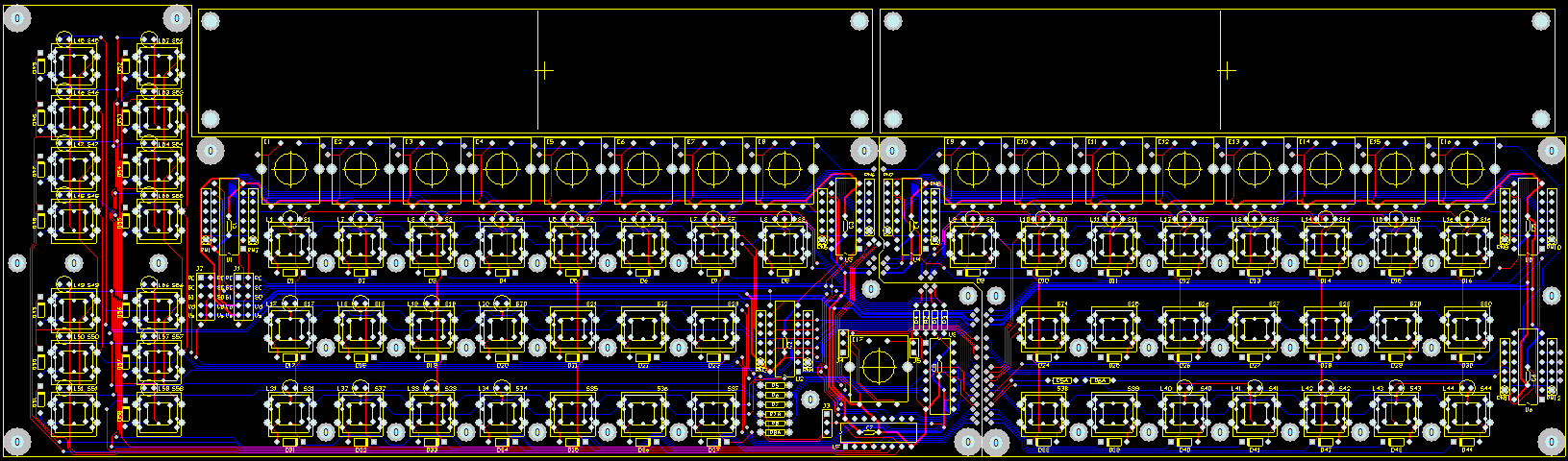
Advantageous: yes. Possible: probably not. It's very tight layout around there. You couldn't do that if the board was one piece anyway. Once those wires are soldered using solid resistor leads (not flexible multi-strand wire), it will effectively be one PCB. Note there's connections across all three parts of the split, so it's sort of reinforced, it can't just bend along one "seam" because the other two are preventing it. The plan is to mount both parts of the PCB to the panel, using switch caps to align them perfectly with panel holes, then do the joining of the PCBs with cut resistor leads on the back side, i.e. bent U-shapes that fit the hole spacing, then solder the joints on the other side for extra strength. If the fab does their job right, those edges should be so exact that they fit together with no gap and the switch caps on either side will align with the holes. A resistor lead will have plenty of clearance from the pads it's going between... I doubt shorts will be a problem; that's the beauty of solder mask! It should be no harder than soldering a ribbon cable to an LCD. The paranoid (like me) can check for shorts between adjacent pads. ;)
-
In case people were curious, here's the PCB layout as a screenshot and PDF printout (A2 page!) And YES, that is a split in the middle, the PCB will come in two parts and require some wiring between them using cut resistor leads. This was done to make it easily produced and shipped - the combined PCB is 16.6" wide, and gold phoenix (the place I got the MB-6582 PCBs) have a max dimension of 14.5" (at least for prototypes, but I'm assuming production runs are the same). bugfight has graciously offered to run the bulk order for the cut resistor leads. MB-SEQ_V3_PCB_snapshot_47.pdf
-
DIN Sync can be done via the expansion port, or you could reuse some of the MIDI sockets. For example, the ultracore allows connections to the PIC18F4620's UART (which is buggy in old versions of this chip)... so there's one MIDI In/Out socket pair for them even though some people might not use it, and then another four MIDI In/Out socket pairs for the four IIC_MIDI modules on the ultracore. If DIN Sync is a feature for which you really want DIN sockets on the panel, maybe it's worth using the first MIDI In/Out socket pair for this, or the fourth IIC_MIDI In/Out. Otherwise, you could use a female DIN plug connected through the expansion port.
-
group buy for ultracore (core + 4x IIC + 8 banksticks)
Wilba replied to ultra's topic in Bulk Orders
Mine arrived today. Thanks ultra! -
Yes, very cool artwork! ... and since everyone else is doing it...
-
Yeah... these photos do not show the LED light colour correctly... they've been white-balanced to the colours of the plastic (and still a bit warm too, oh well)... of course the LED light is way over exposed... IRL they look like normal red and blue LEDs, not these pinky and purply colours. eg. the blue LED one is a nice, not-so-bright blue spot and not as dull as shown in the top two shots.
-
After chatting with bugfight, I'm reverting back to the original plan of panel mount sockets and switch. This avoids the need for an extra PCB and mounting bracket. I estimate the additional cost of this PCB and mounting bracket would be more than the cost difference between el-cheapo PCB mount sockets and snazzy chrome plated panel mount ones like bugfight suggested (but hey I wanted to use these originally so don't give him any credit!). Oh so shiny... Considering some poor guy is going to run a bulk order from Digi-Key for the switches and button caps anyway, surely buying 500 of these sockets wouldn't be much more hassle. :P The 500 price break is $1.53... $15.30 for sockets vs. $5-$10 for PCB mounted sockets + $5 PCB + mounting bracket ($???) + design issues...
-
In the downloads section: http://www.ucapps.de/mios/srio_interconnection_test_v1a.zip
-
Design ideas are welcome, especially relating to the case and sockets. However, the control surface layout was highly optimized and tweaked to make it fit. This is why I've used rectangular buttons instead of round, so there's enough room for a LED above and labels below, and three rows of buttons under the encoders. Encoders, switches, LEDs and DIN/DOUT modules are all on one PCB. It's designed to use the eswitch 12x12mm tact and a rectangular button cap, and discrete 3mm LEDs. Design consideration here was not to force usage of an illuminated switch (or switch with built-in LED) when not all buttons require LEDs. However, the switch footprint on the PCB has alternate pads for MEC's multimec illuminated switches, and for e-switch's TL1240, however, that would require a custom panel and the layout won't be as nice I think. Maybe. I'm preparing an extra PCB to mount the rear sockets, so people can use PCB mount 5-pin DIN sockets. Common and cheap, which is good, and it makes it easy to convert to the rack mountable option - just unscrew this PCB and screw it to the base. The only problem I had with panel mounted MIDI sockets was that the cheap ones look crap, and the nice ones (like the one you linked) are expensive-ish... considering you'll need 10 at the back, that's $27 just for MIDI sockets. It's also another part needing a bulk order. Also, they need to be mounted from the outside, so you could not do something like have an IDC connector on the MIDI In+Out header of the ultracore and split the ribbon cable to two sockets... well you could but then you couldn't move the sockets without desoldering the wires. (I know two SIL connectors would work, but then that's imposing their use too.) I know swapping between desktop and rack-mounted is not something people will do often, but it would be nice if it only required a screwdriver. So you raise an interesting point - should all the rear panel sockets be panel mounted, avoiding the need for another PCB for sockets, a bracket to hold it to the case? Can someone suggest a panel mountable DC power socket and power switch? Should a bulk order for switches and caps, for example, also include these rear panel sockets and switch?
-
Yeah, but I can't take credit for it, I stole the idea from this guy's MIDIbox ;) This "expansion port" is essential - how else are you going to connect the 64 Button/Duo-LED extension? ;)
-
Or read the wiki ;) http://www.midibox.org/dokuwiki/wilba_mb_6582
-
It has crossed my mind to do this, but I thought it wasn't that useful a feature. What advantages are there in having the USB MIDI module built-in? There's already going to be 10 MIDI sockets at the back (for 5 MIDI In, 5 MIDI Out) so it matches what the ultracore can do. I'm laying out a PCB for just the ports and I guess it's possible to add a USB socket which you could connect to the GM5 module, but then what? Do you wire the USB MIDI module in parallel with the MIDI In/Out sockets going into the ultracore? Surely the most flexible solution would be to just put the GM5 module in its own separate box and connect this to the MB-SEQ via the MIDI In/Out sockets, that way it could be used to drive other MIDI devices as well. The other alternative is using the "expansion port" at the back (I'll stick in a DB25 connector) so you can expose whatever other internals you like through that connector - i.e. connections to a USB socket, connections to the AOUT header on the Core, etc. You can hack and splice whatever cables and sockets you like without having to complicate the rear panel's cutouts, or force people to buy sockets just to fill empty holes, etc. (OK, I'm forcing people to do this with a DB25 connector, but they're cheap and easy to find).
-
MB-6582 ate my soldering iron... or ...What Soldering Iron should I get
Wilba replied to lief138's topic in Miscellaneous
This is what I use: http://www.dse.com.au/cgi-bin/dse.storefront/487df36200dc1d28273fc0a87f9c06e4/Product/View/T2250 I like it. The "soldering pencil" bit looks identical to stryd_one's photo, and it has a similar metal stand and sponge holder. -
Mahahaha... I'm calling in your $486.12 debt to me. :D
-
Of course... I have an FPD file already prepared.