Wilba
-
Posts
3,310 -
Joined
-
Last visited
-
Days Won
2
Content Type
Profiles
Forums
Blogs
Gallery
Everything posted by Wilba
-
MB-6582 front panel - I'm about to start. Feedback ... ?
Wilba replied to nebula's topic in MIDIbox User Projects
Yes wiki is out of sync... some people reported problems with the corner screws not sticking before I tried it with success. I suspect they didn't use as much JB-Weld as I did, or different screws, or had NFI (joke!) I had two of the panels from the bulk order to which I glued the screws and spacers (they went to the needy). I used Philips head countersunk screws, and the JB-Weld completely covered the screw head and onto the panel to ~10mm diameter. You can sort of see an example here on a red panel: The red anodized aluminium panel was an experiment in making an Access Virus colour scheme, it also went to the needy and I'm eagerly expecting some more FPE panels in white art on black anodized aluminium. FYI the spacers I used were chrome-plated, and similarly used large blobs so that the main bond is on the outside of the spacer, bonding at least 3mm around the spacer with 3mm up the spacer. Flickr photos show extreme overkill in blob size, you could instead do it in two stages, one with small blobs just to get them attached to the panel, and then a second stage of adding more exactly where you want it... that's what I'm trying in future, so I'm not using so much JB-Weld! In addition, I know from experience that JB-Weld doesn't stick well at all to raw aluminium like you find in the hardware store or something... it's something about the anodized surface that makes it stick, roughening it might actually make it worse, as it's then trying to stick to the raw aluminium which (I hear) oxidises instantly as soon as it's exposed. As long as you keep in mind that the bond is not coming from the space between the panel and screw/spacer but from around it, you should be fine ;D -
I wish I had some German friends who could send some of these to me... :'(
-
Sorry for the hijack Neb... ;) I overstocked on the LCDs you sold me... so any Aussies wanting a couple can PM me.
-
*bump* BTW that was a joke, you're welcome to post to this thread. ;D
-
Man that was quick! I'm posting on Mondays from now on... ;)
-
They look too big. Rear panel hole spacing is 1.2" = 30.48mm But the real limit is the proximity to the stereo jacks beneath them, and the control surface PCB from above. I know the 16mm ones work, only if you cut the leads ;)
-
hehehe I thought you did this already ;) I used 16mm dual gang 500k audio/log taper pots. Linear is fine though, it doesn't really matter. Look like this one but shorter shaft: http://www.altronics.com.au/index.asp?area=item&id=R2296 If someone finds this on Mouser or Reichelt, please post a link. #1, #2 ;)
-
Copper Rocher (an MBSID inside a former-candybox)
Wilba replied to ris8_allo_zen0's topic in MIDIbox of the Week
Well done! It looks like four people could sit around it and tweak knobs at the same time! -
I want to know exactly what the problem was, exactly which joints were bad, where the shorts were, etc. This will help me diagnose any other problems people have in future. For example, you said all the LEDs would light if tested via the JD6, JD7, JD8 pads on the PCB. So I need to know why testing this way (simulating DOUTs) would be different to when it was powered on. Oh and congratulations on fixing it!!!
-
Jump to: http://www.midibox.org/forum/index.php/topic,10788.msg85578.html#msg85578 The following is old news: 6582 SID MEGA-SALE #5 This is #5 because: 6582 SID MEGA-SALE #1: 200 SIDs 6582 SID MEGA-SALE #2: 312 SIDs 6582 SID MEGA-SALE #3: 512 SIDs 6582 SID MEGA-SALE #4: 312 SIDs 6582 SID MEGA-SALE #5: ? ;D You want SIDs? This is your reminder to get your name on the waiting list before I get more. That way I will order enough for everyone on the list when I order. Add yourself to the waiting list here: http://www.midibox.org/dokuwiki/wilba_6582a_sid_mega_sale THE GOODS 6582 (6582A) SIDs are just like 8580 SIDs and not like 6581 SIDs. They have the filter that works best for the MB-SID V2 Bassline mode, low noise, less bugs. Look elsewhere for whether 6582/8580 is better/worse than 6581. I use eight of them in my MB-6582 MB-SID V2 Synth: http://www.midibox.org/dokuwiki/wilba_mb_6582 (but you already knew that) THE DEAL 6582 SIDs cost AU$25 each plus postage and handling fees. I add up the exact cost of SIDs and postage in Australian dollars, and then multiply by 1.0351966873706 to add the handling fee. This means 6582 SIDs now cost approximately AU$25.88 or US$23.18 or 15.67 EUR when including handling fees. Postage will be calculated as the actual cost to post, plus packaging. The PayPal invoice will include the handling fee in the postage amount. Do not email orders to me yet! This is only an announcement that I will be ordering more. I will probably make the order in about three weeks from today, around 13th March 2008, and then contact people on the waiting list to send their orders. If you are already on the waiting list, you don't need to do anything except wait... There is no need to post in this thread. If you post in this thread.... No SIDs for you! No SIDs for you! Come back one year! http://www.youtube.com/watch?v=KpjCn_2H6kE *whack*
-
Yes but for MB-SID V2, you still need one AOUT_NG per Core, two Cores can't share one AOUT_NG to control two filters... although it might be possible for TK to do some magic and make this happen (route one Core's AOUT modulation to a different Core via CAN?)
-
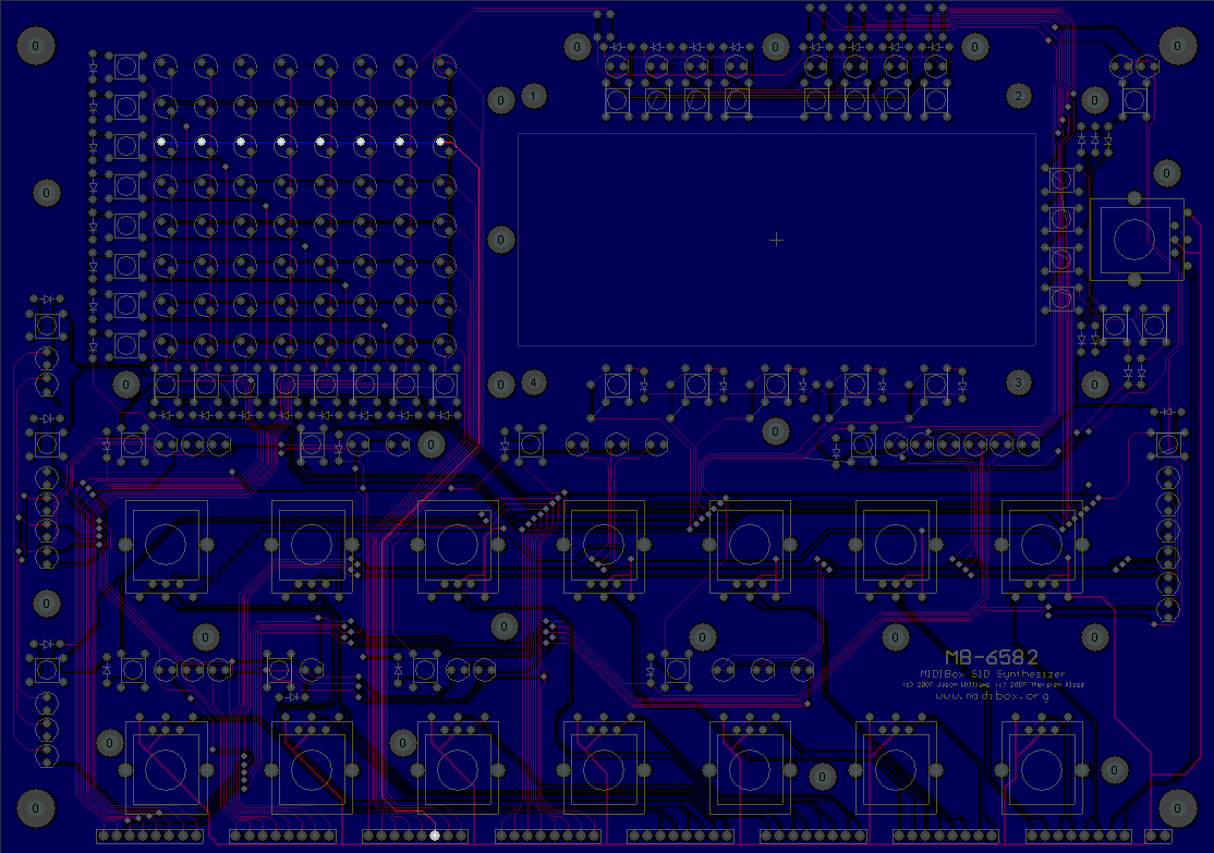
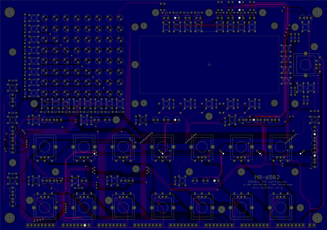
I hear you are still stumped by this problem... and I missed the update to your last post :-[ I would have replied sooner. The second app I uploaded, the one in this post: http://www.midibox.org/forum/index.php/topic,10390.msg78577.html#msg78577 i.e. mb6582_led_matrix_test2.zip should light up all the LEDs, in the mod matrix and everywhere else. I've uploaded two images of the PCB with the traces at fault. Hopefully these can assist you track down a break in the track or something. I would follow the following troubleshooting procedure: Take out shift registers in U21, U22, U23. Connect two wires to J2 on the base PCB, which is between the power switch and the power socket. This is normally used to light the power on LED so it already has a 220 ohm resistor in series. With these wires which we'll call red=5V and black=ground: Directly test the LEDs that don't work in the 3rd matrix row. Put black wire on the lower of the two pins. Make sure the wires are good as well by testing ones that DO work. It's unlikely you have a whole row of blown LEDs but you should validate they all work individually. Assuming the LEDs are good, validate the 8th column of the mod matrix. Put black wire in JD8:D7, red wire in JD6:D0 to JD6:D7. Tell me what you see ;) and I'll think some more


-
That is not so bad if she has other entertainment in mind... ;)
-
Before the Flash chat was introduced, I never knew (or bothered to find out) how to connect to the existing #midibox IRC channel, which had been around for years. When the flash-based chat was added, I started using it because it was so easy to access. I am sure a lot of people new to MIDIbox also try it out, so I'm sure it gets more people in there than #midibox ever did. If you can find a Flash-based chat that interfaces to IRC that would be ideal - I'm voting for the current Flash-based chat purely because it's there, within the browser, easy for everyone to find and use.
-
I'm going to just list the things you need to do in case any one of them was overlooked: Install the hex file in this zip. http://www.ucapps.de/mios/mbsid_interconnection_test_v1a.zip You should be using MIOS Studio with "Feedback from Core" to check you've installed it correctly. Take out only the SID chip from the SID PCB, not the other chips. Use mod wheel messages to control which pin is toggled high. One will be high (5V) the rest low (0V), except for CS# pin which is normally high and therefore toggled low. If your LCD is connected and working, you should see which pin is being toggled high. Check the pin gets changed as you send new mod wheel messages... Unfortunately MIOS Studio doesn't let you send specific mod wheel messages (yet) so you'll need to use MIDI Ox or something else. You don't need other hex files just yet, but you should find them in the installation zip http://www.ucapps.de/mios/midibox_sid_v2_0_rc17.zip Don't worry about changing device IDs yet... use a PIC with device ID 0 in your Core PCB. --- So maybe you're not following the test instructions exactly?
-
Very very cool... P.S. I'm glad someone is making use of all those extra headers ;D
-
The subject suggests you've got two SID PCBs, trying to get stereo SID working. Was one working first and this is the second one that's not working? The second one may not be tested during interconnection test. I think there's another thread about this, TK might have updated the interconnection test to drive both SID PCBs. Also the second one won't work if the extra connection to the Core isn't correct.
-
If the voltages were too low, your SIDs would not be damaged. It's only if you supply too much voltage. I assume you are using 6581 SIDs that require 12V right? 12V supplied to a 8580 or 6582 will kill it though. All SIDs get warm, nothing to worry about there. You have to do the interconnection test with the SID out of the socket. During the interconnection test, are you testing if each pin can be toggled low and high i.e. 0V and 5V? Report back your results, it could be a fault with the PCB or the 74HC595 chips.
-
There is no n00b, it's just me. Are you telling me that if I owned PCBs I didn't want anymore that I must sell them to the people who were waiting the longest, or asked for them first?
-
The joke is mine ;D
-
I was going to buy (trade for) a second-hand HardSID Quattro the other day (just to play with), until I realised I don't have a spare PCI slot in my PC ;D So the USB interface of the HardSID 4U is a definite advantage for people like me, but just looking at the specs, the advantages over a MB-SID with no control surface are basically a faster update rate, which I can't see making much difference, and being able to play samples through the volume register... which is a nice trick, but this was a cool feature when it the SID was inside a C64, when it's being driven by a PC that could just as easily output samples at 44kHz, it's lost some of the charm... you might as well just downsample to 8kHz ;) Having said that, if MB-SID V3 had enough grunt and memory to playback samples, that would be cool. (Yes, I'm unashamedly biased).
-
MIOS Functions Reference Update... Do you want it?
Wilba replied to stryd_one's topic in MIOS programming (C)
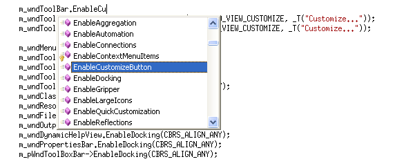
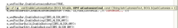
I want Intellisense like in Visual Studio... can you do that stryd?

-
Welcome Foona! It might be a while before you discover that 6582 SIDs sound the same as 8580 SIDs, so if you have no luck finding 8580s then I can help you out with 6582 SIDs instead: http://www.midibox.org/dokuwiki/wilba_6582a_sid_mega_sale
-
Front Panel from Schaeffer: sugesstions on LED holes
Wilba replied to t_xen's topic in Parts Questions
I suggest you measure the LEDs yourself with calipers. In the past, I have specified exactly 3mm holes for LEDs and 3mm LEDs fit in them. However, you could specify 5.25mm to be on the safe side... even if the LEDs were exactly 5mm then any gap would only be 1/8th of a millimeter. -
Re: SID 6581's for sale (8 pieces) and spare Styroflex caps
Wilba replied to SLP's topic in Fleamarket
OOPS! I forgot a not in there.