Wilba
-
Posts
3,310 -
Joined
-
Last visited
-
Days Won
2
Content Type
Profiles
Forums
Blogs
Gallery
Everything posted by Wilba
-
Ordering has closed. Latecomers can go on the waiting list for spares.
-
Ordering for MEGA-SALE #5 has closed. Latecomers can go on the waiting list for MEGA-SALE #6.
-
*bump* Waiting list totals 476 SIDs. Only hours to go... BUT WAIT! THERE'S MORE! I will now include with every SID sold: TWO Mylar Radial 22nF 100V 1% Polyester Capacitors ABSOLUTELY FREE! * Wilba has gone completely mad and bought up all the remaining stock of these capacitors If you purchased SIDs from me in previous orders and want some of these capacitors, just email me, I will send you some for free* too.... eventually.... I might be a little bit busy soon. ;D * postage not included, while stocks last.
-
The values of the capacitors affect the filter cutoff frequency range. Therefore, it is better to use as closely matching values as possible in a stereo SID pair, so the difference in cutoff frequency between the SIDs is as small as possible when both SIDs have the same cutoff parameter. I can definitely hear the difference between closely matching values and values differing by 10% (eg. when using low-pass on a PWM bass patch). I call this a "phasing effect" (probably incorrectly using the term) which is something you might want and can achieve by setting the left and right SIDs with different cutoff values, but it's better to have it optional. Any non-polarized capacitor type will work I think... the differences are more to do with temperature stability and lifespan and other things which I don't know much about. I'm personally using mylar (polyester film?) capacitors with 1% tolerance, a lucky find on eBay, otherwise I'd be stuck trying to find 1% tolerance capacitors of any kind.
-
Quote from top of page: http://www.midibox.org/dokuwiki/wilba_6582a_sid_mega_sale MEGA-SALE #5 is starting. Put your name on the list before March 13th to reserve SIDs from the next batch I get. You will then be contacted by MIDIbox Forum Private Message to send your order details, PayPal email address, etc. I will receive SID shipment around March 20th and commence testing/packing. You will be sent a PayPal invoice before March 27th. You will then pay before April 3rd, and your order shipped between April 3rd and April 10th. Of course, that's a best case scenario... I'm sure there'll be a week delay inserted somewhere in there.
-
I don't understand ???
-
*bump* Last call, anyone wanting 6582A SIDs should get on the waiting list before Thursday, March 13, 2008 (UTC time) View countdown clock
-
*bump* Last call, anyone wanting OPL3 chipsets should get on the waiting list before Thursday, March 13, 2008 (UTC time) View countdown clock
-
OK nag me if I do not wikify this within a week ;) FYI there are only those two "missing features" on the base PCB (backlight and power socket) ;D There's one less-than-perfectly-placed diode on the control surface PCB (left of the Shift button). Also, the "SID R" LED hole on the panel is partially overlapped by the PT-10 mount, requiring some trimming, but that's technically not a PCB error because the LEDs are exactly where I want them (the "SID L/R" button is aligned with the menu encoder).
-
Yes, I agree, which is why a track was put in Base PCB Revision 2 to bridge these two pins. For people fixing up their Revision 1 boards, a cut resistor lead is sufficient to bridge these two pins. If you want a cut resistor lead, I have plenty to give away absolutely free, but you have to pay AU$2 postage. ;D
-
Mmmm... Inkscape rocks.... I think I'm switching ;D
-
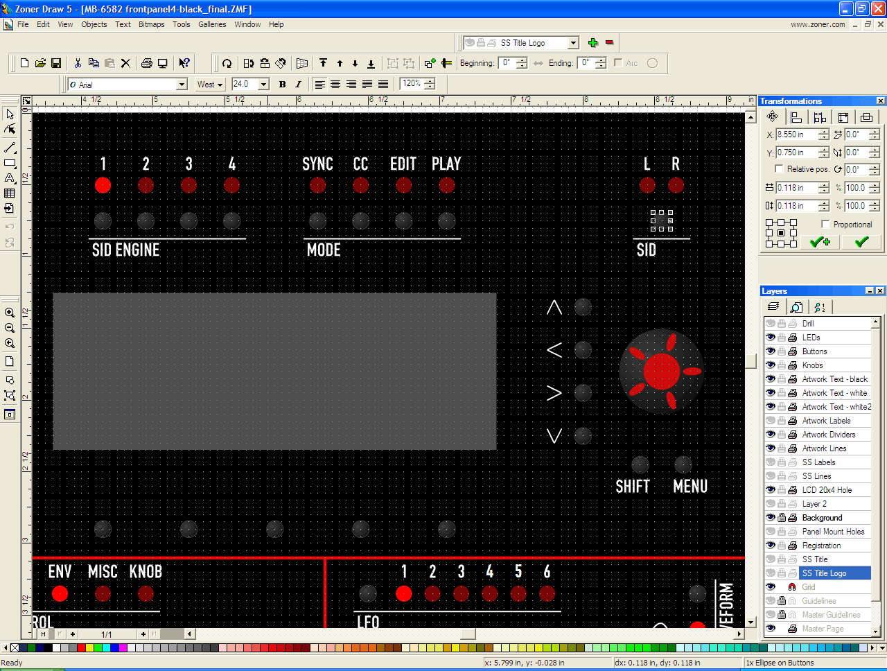
I use Zoner Draw 5. http://www.zoner.com/ I probably will change to something else one day, as I'm not 100% happy with everything it does, but then I like it a lot more than Illustrator because of the way it handles object position/size. Take a look at the screenshot, from one dialog (upper left), I can change the absolute or relative position of things, as well as view what the current position is... handy for then transferring into Front Panel Designer or PCB design software. It can easily do things like creating multiple copies (i.e. an array of buttons/LEDs at given spacings). Also, any place you can type in a dimension/coordinate, you can use any units, handy for working primarily in inches but specifying sizes of components in mm... or drawing up an LCD footprint using mm dimensions from a datasheet. The grid is nice, and you can move things in grid increments using the arrow keys, which is how I mostly move stuff around so that it stays aligned to the grid (unfortunately moving things with the mouse will align the top-left corner of an object to the grid, which is not what you want most of the time). Things like grouping things on multiple layers means I can have a LED made up of a drill crosshair on a "Drill" layer and the LED picture (red circle) on a "LEDs" layer and toggle the visibility of each layer to produce different displays. One limitation though is the "printed page" co-ordinates with origin at top-left instead of bottom-left... not too big a deal though, since you can move the origin in FPD. Another limitation is the exporting, some things don't get exported nicely, so if you really need something that exports perfectly to DXF for laser cutting or something, this will require some tinkering afterwards in AutoCAD... i.e. I think curves come out as stepped line segments instead of circle and arc primitives. It does print nicely, and you can print across multiple A4 pages with registration marks etc. to easily cut and align the pages (if you're doing 19" rack panels, this is a very handy feature for printing mock-ups). I give it a recommended rating ;) because it's not too much CAD like AutoCAD but more CAD than Illustrator... it's very easy to make a sketch of what you want to build, but a little limited in what you can do with it afterwards... since my workflow usually involves using FPD for the panels, I have to manually create the panel in FPD anyway.

-
That wasn't me, that was nILS (aka. the wikinator).
-
To quote from that how-to: Bear in mind that your rectifier and regulator might not have the same pins in the same places as mine. I just think this needs an extra reminder here ;) people have blown up their PSU because of the non-standard bridge rectifier pinout used.
-
Yeah I knew that *cough* I'm just trying to build up my hours of community service by writing lengthy posts. ;)
-
MIDIbox of the Week (MBSEQ V3 in a 2U case made by Julien)
Wilba replied to TK.'s topic in MIDIbox of the Week
Excellent! Congratulations Julien! Great panel layout... threaded blind holes on the reverse side is a great idea! -
Why will velocity of played seq notes ignored for SIDV2?
Wilba replied to Rio's topic in MIDIbox SID
Right. It would not make sense to do this by default. Plus you can have more fun mapping velocity to other parameters or use "K#V" as a second modulation source in the mod matrix (i.e. add it to an envelope or LFO that's modulating filter cutoff). -
It sounds like you've connected switches and encoders to the DIN inputs and not changed the pin assignments in the .asm file to match. So your encoder is connected to the default pin assignments for the SID 1,2,3,4 buttons. How have you connected the switches, encoder (and LEDs, if any) to the DIN/DOUT pins? The "setup_8580.asm" (preferred starting point for you, I think) will be using the default pin assignments as show here: (see PDFs at bottom of this page): http://www.ucapps.de/midibox_sid_manual_hw.html You should modify this file and change: #define CS_MENU_DISPLAYED_ITEMS 5 to #define CS_MENU_DISPLAYED_ITEMS 10 Ignore: ;; NOTE: if CS_MENU_DISPLAYED_ITEMS > 5, you have to adapt the DIN settings ;; in cs_menu_io_tables.inc [/code] as you now configure it in the setup_8580.asm file. Scroll down to: [code] CS_MENU_DIN_TABLE ;; Function name SR# Pin# DIN_ENTRY CS_MENU_BUTTON_Dec, 1, 0 ; only valid if rotary encoder not assigned to these pins DIN_ENTRY CS_MENU_BUTTON_Inc, 1, 1 ; (see mios_tables.inc) and CS_MENU_USE_INCDEC_BUTTONS == 1 DIN_ENTRY CS_MENU_BUTTON_Exec, 1, 2 DIN_ENTRY CS_MENU_BUTTON_Sel1, 1, 7 DIN_ENTRY CS_MENU_BUTTON_Sel2, 1, 6 DIN_ENTRY CS_MENU_BUTTON_Sel3, 1, 5 DIN_ENTRY CS_MENU_BUTTON_Sel4, 1, 4 DIN_ENTRY CS_MENU_BUTTON_Sel5, 1, 3 DIN_ENTRY CS_MENU_BUTTON_Sel6, 0, 0 ; define this if CS_MENU_DISPLAYED_ITEMS > 5 DIN_ENTRY CS_MENU_BUTTON_Sel7, 0, 0 ; define this if CS_MENU_DISPLAYED_ITEMS > 5 DIN_ENTRY CS_MENU_BUTTON_Sel8, 0, 0 ; define this if CS_MENU_DISPLAYED_ITEMS > 5 DIN_ENTRY CS_MENU_BUTTON_Sel9, 0, 0 ; define this if CS_MENU_DISPLAYED_ITEMS > 5 DIN_ENTRY CS_MENU_BUTTON_Sel10, 0, 0 ; define this if CS_MENU_DISPLAYED_ITEMS > 5 ... and change the "SR#" and "Pin" to match your pin assignments. You can compare how these match the default DIN assignments in the PDF (i.e. to understand how "SH#" and "Pin" relates to a pin on the DIN module). For buttons you don't have connected (i.e. perhaps "SID 1" and others in the rest of the table), set SR# and Pin to 0 each (like the default for CS_MENU_BUTTON_Sel6). Now scroll down further: MIOS_ENC_PIN_TABLE ;; SR Pin Mode #if CS_MENU_USE_INCDEC_BUTTONS == 0 ENC_ENTRY 1, 0, MIOS_ENC_MODE_DETENTED2 ; menu encoder #endif ;; additional CS encoders ;; SR Pin Mode ENC_ENTRY 3, 0, MIOS_ENC_MODE_DETENTED2 ; Osc delay/transpose/assign #1 ENC_ENTRY 3, 2, MIOS_ENC_MODE_DETENTED2 ; Osc attack/finetune/assign #2 ENC_ENTRY 3, 4, MIOS_ENC_MODE_DETENTED2 ; Osc decay/portamento/assign #3 ENC_ENTRY 3, 6, MIOS_ENC_MODE_DETENTED2 ; Osc sustain/release/assign #4 ENC_ENTRY 3, 8, MIOS_ENC_MODE_DETENTED2 ; Osc release/pulsewidth/assign #5 ENC_ENTRY 4, 6, MIOS_ENC_MODE_DETENTED2 ; LFO rate ENC_ENTRY 5, 0, MIOS_ENC_MODE_DETENTED2 ; LFO depth ENC_ENTRY 5, 4, MIOS_ENC_MODE_DETENTED2 ; Filter CutOff ENC_ENTRY 5, 6, MIOS_ENC_MODE_DETENTED2 ; Filter Resonance ENC_ENTRY 6, 0, MIOS_ENC_MODE_DETENTED2 ; Env depth/assign #1 ENC_ENTRY 6, 2, MIOS_ENC_MODE_DETENTED2 ; Env attack/assign #2 ENC_ENTRY 6, 4, MIOS_ENC_MODE_DETENTED2 ; Env decay/assign #3 ENC_ENTRY 6, 6, MIOS_ENC_MODE_DETENTED2 ; Env sustain/assign #4 ENC_ENTRY 7, 0, MIOS_ENC_MODE_DETENTED2 ; Env release/assign #5 ;; don't remove this "end-of-table" entry! ENC_EOT [/code] This is where encoders are mapped to DIN pins. Change the first one's SR and pin numbers: [code] #if CS_MENU_USE_INCDEC_BUTTONS == 0 ENC_ENTRY 1, 0, MIOS_ENC_MODE_DETENTED2 ; menu encoder #endif to match where you've connected the menu encoder. I'm assuming you can do the same trick and assign SR=0, Pin=0 to the other ones which you are not using, in case you're using a 3rd DIN shift register (i.e. J7,J8,J9,J10 on a DINX4 module) for switches. You don't want the app to think you've got an encoder there when there are really switches. And just in case you don't know, you'll have to rebuild the setup_8580.asm into a new setup_8580.hex file. Learn how to do this here: http://www.ucapps.de/howto_tools_gpasm.html
-
Why will velocity of played seq notes ignored for SIDV2?
Wilba replied to Rio's topic in MIDIbox SID
You have to actually map velocity (K#V) to a parameter. Mapping it to volume (i.e. the SID's volume register) isn't that great, as with a lower volume, the noise floor goes up. Don't ask me why. Mapping to "Sustain OSC#123" is a better option and works the same way for oscillator envelopes where A=0 and D=0. -
I doubt it is going to be that widespread... based on PCBs sold/wanted, I guess it will reach about 300 eventually. Well... of course it feels good to know your work is admired and people want to build one too... but I am totally amazed about how many SID fans are out there, and I hope they all have enough electronics experience to build their own without many problems (and thus not have too much troubleshooting on forum). Also, with so many people wanting to build one, it makes bulk orders a nightmare... so people who got the PCBs way back in August '07 (?) have been waiting months for SmashTV to sell the base PCB parts kit... imagine trying to run a bulk order for 100 people for 30 (?) different parts... not all of which are available, and you can't ship anything until they're all in hand. And then, after these first 100 kits are done, there'll be an instant demand for another 100+ as soon as SmashTV has PCBs to sell... I mean, why wouldn't you buy a kit when buying the new PCBs, when they'll be cheaper than anywhere else, the exact parts that fit, and combined shipping?) BTW I have to add, everyone wanting kits OR PCBs should read this all carefully, especially the bit about the notification list): http://www.midibox.org/dokuwiki/wilba_mb_6582_pcbthread
-
MIDIbox of the Week (MBSID V2 Keyboard Version made by Alkex)
Wilba replied to TK.'s topic in MIDIbox of the Week
Thanks for the photo shoot! I love seeing this stuff. BTW my latest panels were made by FPE so I also "vectorized" (or rather, "HPGL-ized" the waveform icons)... my latest FPD files are published, and I can supply HPGL files for just the waveforms if people want them. I've also worked out a good workflow to get designs in HPGL format, so anyone interested in this kind of thing can contact me for more info. -
MIDIbox of the Week (MBSID V2 Keyboard Version made by Alkex)
Wilba replied to TK.'s topic in MIDIbox of the Week
Awesome! Alkex, can you share more photos? I'd love to see more detail of the frontpanel. -
Anyone who has not received their SIDs yet, please email me. But first, go visit your local post office and ask if a parcel has been held for you and you weren't notified they were doing so.
-
*bump* Waiting list totals 329 SIDs. 10 days left. THIS MIGHT BE THE LAST WILBA'S 6582A SID MEGA-SALE EVER! Do you leave it to chance that I might stay insane and continue to risk thousands of dollars of my own cash in shady deals with the dark underworld of obsolete chip brokerage? BUT WAIT! THERE'S MORE! For just 5 cents more, I'll also throw in: Rugged anti-static IC tube, tested to withstand up to two picotonnes of force! Professionally printed mailing labels for destination and sender! Stiff cardboard envelope, sealed with Wilba's special brand of transparent adhesive tape! CALL NOW!
-
Upload a different application?