illogik
-
Posts
381 -
Joined
-
Last visited
illogik's Achievements
MIDIbox Tweaker (3/4)
0
Reputation
-

Problems running app on new STM32F407G-DISC1 pcb
illogik replied to illogik's topic in Testing/Troubleshooting
Hi Thorsten! I didn't notice your reply until now. Thats what i did (well actually i soldered the points of jumper SB10 to a pinheader so i can put a jumper on or off. Here is a pic. The reason why the pinheader/jumper isn't connected to the the actual pads of SB10 is that when i tried to do that, one of it's pads came off due to overheating. So i checked the schematic and found out what SB10 does is shorting out capacitor C11. Capacitor C11 is connected between the NRST pin of the STM32F4 ic, and GND. So if you use jumper S10 you short the NRST pin to GND So as you can see (kinda); i soldered a wire to the top contact of C11 and took a ground pin from the P1 port. It works, but i immediately got stuck again. I'm planning to use this core for a mbcv_v2 system, and the lcd is not working, i posted on this in the MIDIbox CV V2 concept thread. I guess the issue has something to do with both this particular STM board and the CV_V2 app; because the LCD does work properly when i only have bootloader or when i upload other app (tried mbseq_v4) on this core. cheers, marcel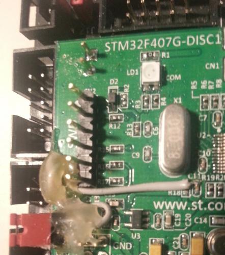
-
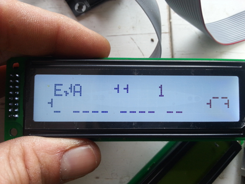
Hi Guys, I'm running in a problem also with the app.. The LCD doesn't work properly. See picture. I guess this may have to do with the newer discovery board i'm using (STM32F407G)? see also this thread. When i upload another app or with bootloader only the LCD does work. Also every time the LCD behaves differently; one time as on picture, other time only black blocks, other time nothing..? cheers, marcel
-
Hi, i replied to this discussion: http://midibox.org/forums/topic/19987-goom-stm32f4-usb-problems/ but i guess the board is a better place for it? Maybe someone could move it here. In short, the original poster and me both have similar problems with the new stm32f4 discovery pcb (STM32F407G-DISC1). The app will not run if only powered from micro usb; i think it has to do with a new ST-Link (ST-LINK V2A compared to the old ST-LINKV2) that is on the newer boards. According to the datasheet the new ST-Link has a know limitation; Activating the readout protection on ST-LINK/V2-A target, prevents the targetapplication from running afterwards. The target readout protection must be kept disabled on ST-LINK/V2-A boards. See the original thread for more details. So is this an issue or are we doing something wrong? thanks in advance, marcel
-
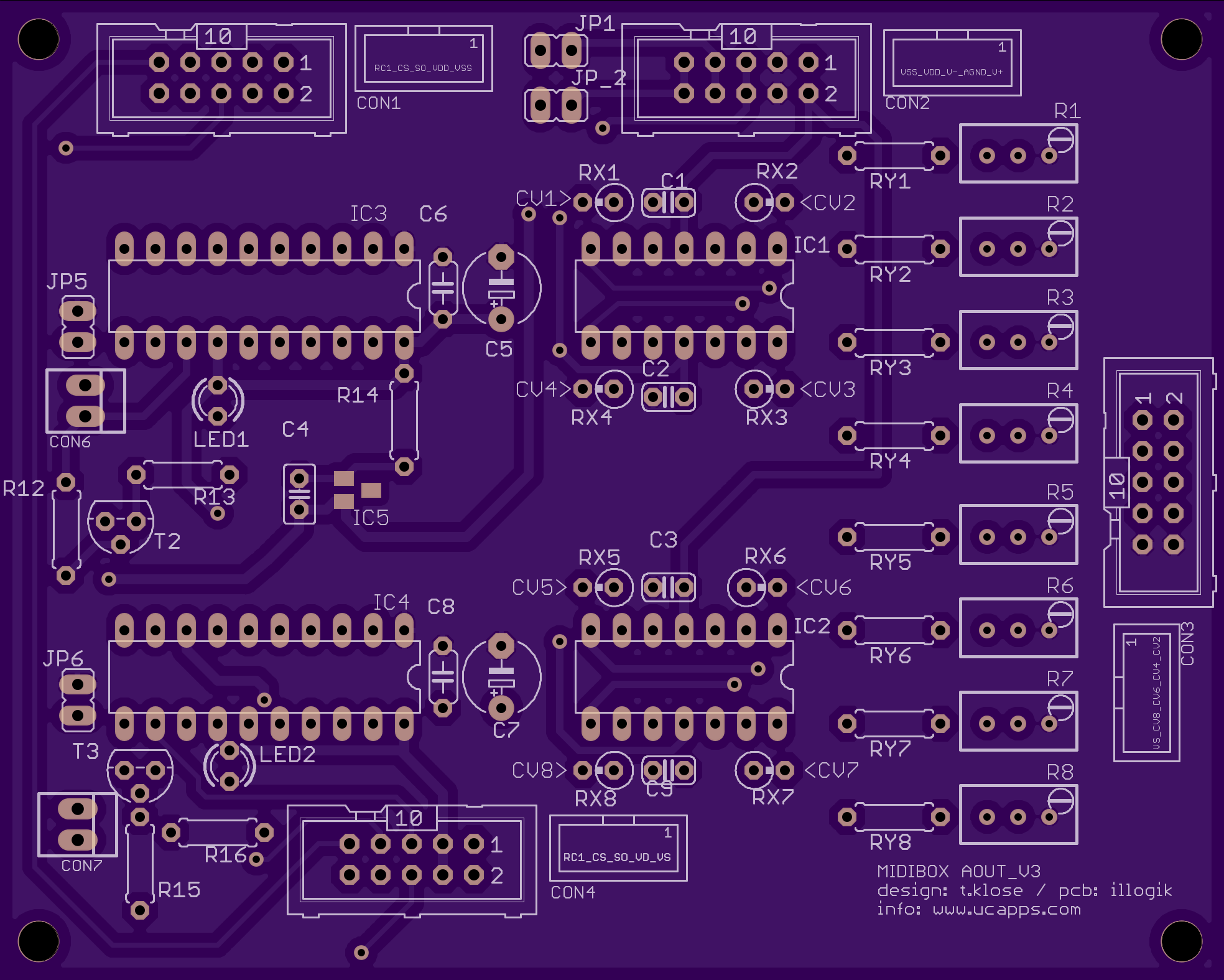
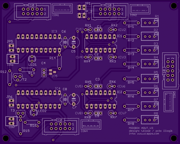
Hey guys, long time.. haha I havent been active here for a while but did a lot of midiboxing last year, finally built a seq and helped a friend with building one.. needless te say here but still : really nice!! Anyway, I need to build a few AOUT modules for the 2 seq's and a midibox_cv2 so I decided to have some pcb's made. I had contact with northernlightx from the forum a few years ago; he was busy with designing a new pcb for the mbhp_AOUT module (max525 version). He had some made but didn't work; he sent them to me so I could help. I found that there were a couple of mistakes on the pcb; had to cut too much traces and the layout wasn't good (confusing, no names/labelling). Let me say: for me this aout pcb is really something that has to be good quality; ie. clear, efficient, optimized to produce the best signal possible: because it is central in my setup; it provides the connection from midi to modular synthesis AND because it is quite an expensive module (max525ACPP around 35 euros); so that is why i'm quite critical about this pcb. So I decided to make a new pcb for the AOUT module which I will have made at OSH park soon, but I think if it is a good design it could be put on ucapps as the AOUT_V2 pcb. So before I have them made, I thought to share it here and see if I forgot something, should do something different etc. If so, let me know so I can make some adjustments/improvements and order some boards. I will then of course build and test them and report back here.. If they work correctly the design can be put on the site as the (long awaited) AOUT_v2 pcb These are things I had in mind while designing: -how to adress analog/digital ground stuff -clear labelling of test points, components, trimmers, in- and outputs -clear layout, enough room for trimpots that are a bit bigger -all connectors should be (2x5) IDC connectors -bipolar option will be possible with extra hardware; more on that later -power led not included The design shown below is just to get the idea and to see the stuff I find important. Im actually working on another version with different/better tracing. I'll add the eagle files so you can have a better look. -how to adress analog/digital ground stuff so I used top and bottom ground planes; top ground plane is analog ground, bottom has 2 groundplanes, the biggest on the right side is analog ground, the smaller left plane is digital ground. I have the 6007b placed on top (original was bottom); the area on the bottom around the 6007 has no ground plane to avoid capacitance problems. About tie-ing grounds; he max525 datasheet says connect the 2 grounds together close to the max535 to the best ground trace. JP5 and JP6 connect the grounds together (should I keep this? Have them to be safe because I dont know anything about the math or processes that are involved with proper grounding, I just try to learn& apply the best grounding practice) I have jumpers JP1 and JP2 so you can decide if you get digital power from the power connector (CON2) and send it to your core (with CON1) or if you only get analog power from CON2 and get digital power from the core (CON1). -clear labelling of test points, components, trimmers, in- and outputs -clear layout, enough room for trimpots that are a bit bigger -all connectors should be (2x5) IDC connectors first off, I made some icons with pin names next to all of the IDC connectors. I see that in the image above half of the pin names don't show up but ill fix that. I didn't make separate test pins for calibrating the outputs because the RX-* resistors are perfect for that. Note the labels inducating the CV out number. The trimpots are in order; top to bottom is cv out 1 to 8. There is room around the trimmers so they can be a bit bigger. Also the IDC connector for the outputs (CON3) has the outputs in order. Pin 1 to 8 of connector are CV out 1 to 8. -bipolar option will be possible with extra hardware; so I thought A LOT about this since years ago I tried making the bipolar option and had problems. I know for sure that it is possible to make some hardware that will let you switch between an offset of +/- -5V and 0V. (there was some talk about this in the CV-V2 thread and maybe some other forum pages) I would guess it would be possible to make it so you can decide on a patch/preset level wich output should be bipolar; this would be the best approach for me. If I want to send notes to a module want an unipolar out but if im controlling other stuff a bipolar would sometimes be better. But I wouldn't know how to program that so i'm just putting the idea out there. In practice the expansion hardware could be basically an 2 input inverted opamp mixer with matched resistors for the so you have a gain of exactly 1 on both channels. One mixer input will be the calibrated cv output from the AOUT pcb and the other mixer input should be a signal (provided on the expansion pcb) that you can switch from 0v (unipolar) to -5V (bipolar).To make a stable -5V you could use a zener voltage regulator, and then there should be some kind of digitally controlled switch that can be controlled by a DOUT pin to send either 0V or -5V to the opamp. Haven't designed this yet but should be easy. The output of the inverting mixer should be inverted again.. Of course you could think; use an non-inverting mixer, but the gain formula of that is not so straightforwrd and I think that was the reason for my problems with using the original bipolar expansion.. But if anyone has a better option; less opamps is always better I guess. Few questions on this: should we take the calibrated, amplified CV outs or the direct outputs of the max525? I those the first option because then it is a true expansion as in you can use and calibrate the AOUT standalone and just add the expansion if you need it. To implement the opamp mixer correctly it should have a gain of exactly 1 otherwise the calibrated voltage will be off. Do you think we can do this by using precisely mmatched resistors? Hmm sorry that was maybe a bit much about the possible expansion.. now back to the AOUT finally some questions I still have about the AOUT_v2 pcb design: -should the 2 gate outputs be there? I guess so right, doesn't cost a lot and you have some visual aid to see if the module is responding to midi/core - should there be a connector for chaining th SPI port (dunno if I name it correctly) but like port J2 at the original out module? Is it ever possible to chain more AOUT modules together? I did put it in the design (CON4) but don't know if I did the connections right; maybe someone could check that? Allright guys lemme know what you think.. cheers, marcel AOUT_V2_prot.zip
-
hi; i have the same problem with the new stm32f407G discovery; it's installed on a CORE_STM32F4 module and i'm running a build of the cv_v2 application. ST-link utility workes good: i can flash the bootloader; LCD shows bootloader is up. I then use the micro usb to install te midibox_cv_v2 app with mios studio: all works fine; osx recognizes the midibox cv midi ports. when i then power off and connect only with micro usb (and jumper J17) the application doesn't start; the oleds (that worked before) stay off and osx doesn't see the midi ports. (The LCD shows black blocks but that may be a different issue) When I then also re-connect the mini usb cable to the pc wich ran the ST-link utility the application starts oleds turn on, osx recognizes the midi ports. Then if I remove the mini usb, the application stays up. I just cannot boot up with micro-usb only. I googled & found this forum discussion which seems about the same issue (concerning the new STM32F407G module) http://electronics.stackexchange.com/questions/221895/stm32f407g-disc1-not-working-if-not-connected-to-pc Basically someone has similar problems with the new STM32F407GDISC board, before he used the old discovery board without problems. A guy answers that he “fixed” the problem by soldering a jumper (SB10) on the back of the pcb ; he says “SB10 forces the ST-link mcu in reset state.” but then warns that you can't use the st-link utility anymore. So I checked the datasheet of the new STM32F407GDISC. http://www.st.com/st-web-ui/static/active/cn/resource/technical/document/user_manual/DM00039084.pdf It says the 407G has a new ST-LINK >> ST-linkV2-A (Old one of the STM32F4DISCOVERY board was ST-linkV2). It then talks about a limitation of the new version: Known limitation: Activating the readout protection on ST-LINK/V2-A target, prevents the targetapplication from running afterwards. The target readout protection must be kept disabled on ST-LINK/V2-A boards. So I guessed this might be the cause of the problem, I did a bit of searching but couldn't find anything about it. Anybody knows what to do? Cheers, marcel
-
Hi Kristal= , did you get any info on this? i'm interested if these profiles are easily available cheers!
-
the reason i am so enthousiastic is beacuse for the last 1,5 year i have been using the unofficial predecessor of the MBCV2 extensively in my studio/modular system: which in essence is a MBSIDV2 with NO sid's connected, used only as a midi to cv converter with loads of additional modulation- and patch possibilities. It is a very important piece of gear to me. so needless to say i was really happy when i read about the MBCV2. Also i've beeen helping Alex with the redesign of the AOUT module. I will try to post all my ideas/comments & issues (about features that are allready implemented in MBSIDv2) this week. cheers, marcel
-
Hi thorsten and all, i have been meaning to get involved again here with MBCV2 for almost a year now but haven't done so , mainly beacause i have a lot of ideas/input concerning hard & software features and didn't put them on "paper" yet, wanted to do that in one go, but maybe i should just start setting it in motion by posting: ........NIIIIIIIIIIIIIIIIIIIICCCCCEEEEEEEEE!!!!!! you even implemented a feature that i had in mind (as in recently i thought i should have a oscilloscope module in my modular) but did't think of as a possible feature of de MBCV!! for me this would really be an extremely useful addition to the midi to cv part of my system. For me, having visual feedback about complex modulation processes and synthesis in general has always been very eye-opening and will increase the creative process in making sound or music cheers, marcel
-
check diss: http://www.midibox.org/dokuwiki/fix_for_skipping_encoders cheers, marcel
-
:) :D ;D oohmy ; i've been thinking about using lfo/envelope/modmatrix from mbsid as startingpoint for a cv interface, but this is more easy then i imagined, just use a downstripped mbsid (only make controls for lfo&envelopes +possibly modmatrix) i'm gonna fink about implementing this. great! thats it.. i'm back
-
hi everybody! i'm jumping in because i may have some interesting info about this, or maybe i am a bit misinformed myself, hear me out.. The korg EX800 has a lot of family.. big brother: Poly 800 (korg) cousins from italy: DK80 and EX80 (siel) and the little known half sister, lives in japan: SX-500 (suzuki) i was thinking the basics of these machines are similar (especially the ex800/ex80/sx500)... assuming this is true, i have some information which will you find useful; the Siel EX80 and the Suzuki SX500 (which i own) have midi implementation of all parameters! it wasn't easy to find but there is a midi CC# implementation chart on this SIEL website.. http://home-1.worldonline.nl/~smeyer/siel/ so if you set up a midicontroller or build a dedicated one for this machine, you can control all parameters in real time i don't suppose the korg is the only one in the family which lacks this feature? so yes i think it is possible to just make patches for this machine with a midibox64(E) in patch mode, but if this is all true; i don't really understand what these guys are up to: (i havent read everything properly so probably i just missed the point) (+_+) i don't share this opinion; i did the dragon slayer mod, and i love it! especially having resonance up to self oscillation (and more)... sonic mayhem!! for me having (non midi) analog pots on a midi controlled device is great; use one midisequence (you can even use cc# for filter cut and/or res) and offset it with the pot one thing though, i remember the tutorial for doing it was for the korg (or siel) and i had to do it a little different on the suzuki cheers, marcel
-
hi, www.cgs.synth.net also got two (non standard!) VCF designs: the Synthacon filter (has simultanious LP BP HP inputs!) and the Bi-N-Tic filter; which is a mix between a vcf and an oscillator, maybe a bit overkill for your needs but verrry interesting cheers, marcel ps ¿how do you know for sure that you are highly infected by midibox? ...when on vacation in bolivia you still find yourself posting on this forum :P oh well see you guys in 6 weeks (or less... ;D)
-
for doing what??
-
Analog effects, was "Midifiying a sega genesis"
illogik replied to stryd_one's topic in Miscellaneous
hey drbunsen, yeah i know the site, nice documentation/projects. but i haven't seen anything on voltage controlled resistors there; are you talking about "VCR" under "modules"? because this is a VC (spring!) Reverb ;D -
hey stryd and all, you are aware that on hallucinogens site there is allready pcb artwork for all individual voices? take also a look at the concussor series; drummodules from analogue solutions they cloned some favorite drumvoices but put an extra cv input for pitch on some, for instance the BD99 (tr909 kick clone). Then you can have the normal 909 sound but you can also modulate the pitch with an envelope or fast running LFO to get a totally different sound. man i'm looking forward to seeing some custom built drummachines in the midibox gallery (and on my desk) next year ;D