m00dawg
-
Posts
1,404 -
Joined
-
Last visited
-
Days Won
16
Content Type
Profiles
Forums
Blogs
Gallery
Everything posted by m00dawg
-
Hi Woolsey! Welcome to the forums (I see you haven't popped your 10 posts cherry yet so thought I'd say welcome). To answer your question, yes, you can use a 2x40 display. All that need be done is to change a single value in one of the source code files and rebuild it as far as I know.
-
Might want to check for cut tracks, just in case. It does seem odd that they are the only ones. Could indicate a bad pin on one of the ICs but I would have expected to see more bad LEDs if so. Still, might not hurt to try swapping them out. Unfortunately, I forget which ICs relate to the LEDs on teh Sammich :) Perhaps someone can chime in here? I'm at work so I can't easily look at my own synth at the moment.
-
Turns out, I may still get my 4x20 after all. I found this off CrystalFontz and it is noticeably smaller, although I wonder if it might be too small. I don't want to sacrifice usability just to have a cool animated bar. Hmm...decisions, decisions!
-
Have you tried simply replacing the LEDs? Or seeing if you get any signs of life using multimeter?
-
The bar is something I'll miss as I knew it displayed that. It was mostly the other stuff. So the other row of text is just for hierarchy? If that's all I can likely live without that. Thanks for the info!
-
I know the 4x20's look much cooler but I realized last night that the amount of usable space on my 3U rack panel was less than I thought due to the actual chassis the panel sits behind behind shorter than I originally thought. The problem is that my LCD board is as small as I can make it when using a 2x40 LCD. So in order to fit everything into the smaller space I now have, I have to the filter and LFO sections, which site below the LCD, vertically asymmetric to the OSC and ENV sections (which are to the right of the LCD). So far, that looks weird :) Similarly, I don't have enough width to orient the filter and LFO knobs with the OSC and ENV sections as that leaves too little space for the mod matrix unless I removed the menu knob (and then what's the point). So, in light of my asymmetry or space constraints, I was thinking of going with a 2x20 LCD matrix instead. I know that's the "standard" size anyway but wanted to check from people who have used both, other than it looking cool, is the 4x20 significantly more functional?
-
Ok board layout updated to use SMD diodes, among other minor edits. Turned out pretty well and saved a tiny amount of space. I could not bring in the dimensions of the board much more without Eagle complaining. I may be able to push those limits depending on what 4pcb or BatchPCB's design limits actually are. I also noticed I can shave like .025" by using smaller wire, though I hope people are not quite that space constrained. In any case, the changes can be found here. I also included a parts list with a link to some SMD diodes I found on Mouser that should work.
-
Agreed! I went ahead and put in the DO214AC, though I put in the smaller of the two. The larger one had me a tiny bit worried about any bridges. I'll post an update here once I have some extra time (still at my day job :) ). I, too, am ok with green. Purple sounded neat but, I mean, who is going to see them :) Unless someone is making a clear control panel of course.
-
Yeah you can put whatever quantity you'd like :) It's just a tally until we meet the minimum number of orders, at which time I'll start checking with people to see who still wants them and then if the final count is still above the minimum, we can start going. The 4 week lead time is akin to BatchPCB. I would expect 6-8 weeks all told for people to get their boards at least to international places. I'll iron that out if/once we hit the minimum amount of boards. I didn't put it down yet, but we can have choice of fancy colors if people care about that sort of thing (there's a cost difference so keep that in mind). I know people liked red for the GM5x5x5 boards for instance. Finally, here are some SMD options in case there needs to be discussion about which parts to use. This is what I found in EagleCAD just looking at random diodes, so it's not matched to any specific ones, though I would imagine there would be signaling diodes that we need in most all the packages. In order: * MICROMELF-R * MICROMELF-W * MINIMELF * DO-214AC * DO214AC The last two I guess are variants of each other. There's more in Eagle but some didn't fit without running into the pads. It seems like the MINIMELF and DO214AC pads are close enough such that people could use either/or. I haven't looked at specific parts on Mouser yet for these - just wanted to share some random findings :)
-
@ilmenator That's about what I was thinking. I wasn't sure about the way the solder would flow off the barrel since I'm used to components with a direct contact to the pad. Doesn't seem terribly difficult and I like not having through holes there. @rosch The through-holes could become a problem as they are quite close to the border of the button. Soldering the diode on the underside helps, but it still has leads that would poke out and need to be trimmed. I agree with ilmenator that SMD is a good way to go and may be a nice practice board before going to the GM5 or OPL3. Not really much to mess up for something like a diode. But, as far as a bulk order goes, as long as functionally the non-SMD board works, then I guess it's more up to those interested. @Flying Panther Ask and ye shall receive :)
-
Ah ok. I was actually thinking about the flat-mount SMD devices (so basically like the one I linked to but with only two pads). Is there a particular technique to MELF's? I see glue is recommended to keep them in place until you solder them. What about the soldering technique anything concerning there? I guess I'll see what's available in EagleCAD and go from there :) Really, if it's just SMD pads, I wonder if I can make a design that would work for flat or MELF-mounts (seems like that is plausible).
-
I was thinking about that last night too. Are you referring to something like this? I would have to see it a bit closer to know how much of a pain that could be but it's probably easier than soldering the GM5 (which was actually not bad, just slow) and, yeah, I agree, that would totally solve the problem of the diodes messing up the buttons. Actually, I was thinking about use SMD buttons for another board (the one surrounding the LCD panel) but was worried about alignment being a problem if one wasn't spot-on with the surface soldering. That and I can't find SMB 6x6 buttons with a 13 or 15mm button-length.
-
Didn't think of looking at Mouser, oops :) I was looking at McMaster as that is where I went for all the screw hardware for the MB-6582. 9mm may work just about perfect since the height of the encoders (other than the shaft obviously) seems to be around 8.25mm or so. Having a little more of the buttons pop out of the panel seems like a benefit as long as it's not too far anyway. I also didn't think of using the male/female spacers, that's actually a very good idea! I always write those off unfairly but in this case, that's perfect. I was going to use just a long screw to go through that shaft, but that seems silly over just using the male/female spacers. Thanks for the ideas!
-
I know the MB-6582 CS design calls for 10mm spacers and a 1.5mm panel (or 11.5mm total). Since I will be using a rackmount CS design, I don't need to worry about the panel thickness as much (there is no groove I need the panel to fit into). So I was going to go with a standard 2mm panel. That means that I would need 9.5mm spacers to keep the same dimensions. I found 3/8", but that is 9.525 and I was worried the extra space might make the buttons sink in too much. So, I was thinking of going with 8mm spacers (or 10mm total) but then the encoders may not fit in the gap. So, yet another option is to get the 6x6x15.85mm switches (instead of the 6x6x12mm). Anyone have any thoughts on those or my options in general? I can put in a request for the 1.5mm panel, but I do want something that will last and, if I don't have to worry about the panel width as much, I was thinking I should get a panel that doesn't raise a red flag with FrontPanel Express?
-
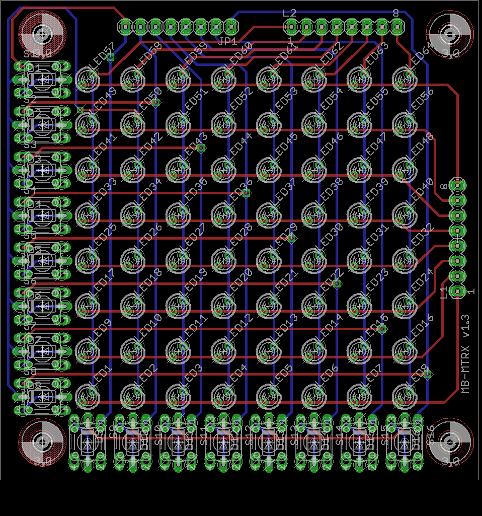
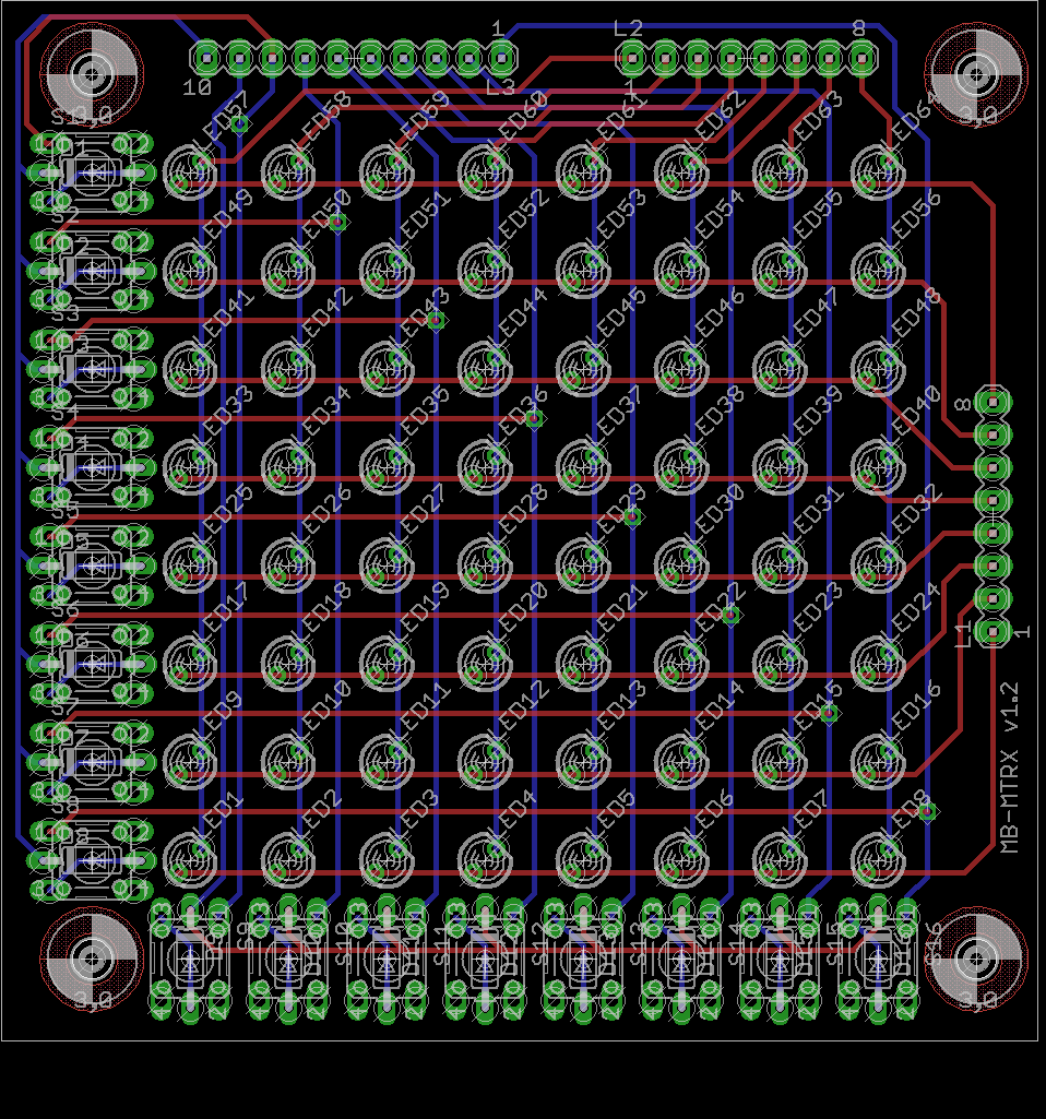
Well, that puts us up to 5 :) Also, here is the revision sharing the LED pins. I'm pretty sure that's right but not sure enough to order any boards just yet :) I opted to share those pins since I am going to use the MB-6582 baseboard for my synth. Wilba's transistor sink magic, though I don't quite understand it, could be applicable elsewhere too. If enough people are interested, I guess we'll need to see what everyone would prefer there. EDIT: 4pcb came back. 25 boards @ 3-day turn-around ends up being $15.08 each (not including shipping). I need to talk to someone there but there is also an option for longer leader times. 4-week lead time, for instance brings the cost for 25 down to $9.37. Don't yet know about shipping since that will drive the costs up for everyone just a bit (since it has to get shipped to me then out to everyone). I'm in the US so I'm not sure how international rates apply there (haven't done that before :) )
-
Doh! I realized I can save 2 pins by using JD8-D1 and JD8-D2 from the LED headers. Wilba, if you happen to see this, can you confirm this is correct? The button wiring diagram for the MB-6582 didn't include the matrix buttons, so I went off the MB-6582 control surface board layout itself.
-
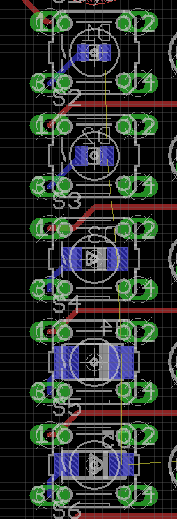
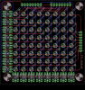
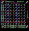
Howdy Folks! I was hoping to get some feedback on some changes I made to my LED Matrix board. To save on space, I opted to mount the diodes for the buttons under the button itself. I was thinking I could solder the diodes on the back side to avoid solder blobs that might prevent the button from mounting flush. I was curious as to people's thoughts on if this is a good idea? It saves a ton of space and, otherwise, I would have to shift everything over on my control surface which I wanted to avoid since I'm otherwise happy with my layout. This is not a board I care to etch on my own so I was going to order it from BatchPCB though if enough people were interested (25 seems to be the magic number), I was going to see about organizing a bulk order.
-
I know how the NES and SNES controllers work (shift registers basically) though it's been a while. If you're familiar with Linux, have a look at the Linux kernel source documentation. I forgot the exact module name (gamepad maybe) but it has tons of documentation about how to connect stuff all the way back to the Atari 2600 up to at least the PS2 controllers (not sure about the 360). You could get some good knowledge from that. The docs for the NES and SNES controllers were awesome.
-
GM5 is not what you want. Have a look at the MidiBox64 instead as it handles buttons. Really, what you need is a CORE plus one or more DIN modules. If you're in the states, SmashTV's shop has boards for both. You can also use AIN modules for analog inputs if you wanted to use joysticks with an axis (as opposed to buttons)
-
In the interim, you could look at this. It is not useful for live changes but if it's a matter of tweaking patches, or making new ones, the V2 editor is very helpful.
-
Eagle Part for the Neutrik TRS Jacks on the MB-6582?
m00dawg replied to m00dawg's topic in Parts Questions
Made a few revisions mostly to widen the holes for the pins and fix the placement of the ground pins (they were every so slightly off). Button the connector next to the library print-out indicates it should work, so I went ahead and put it on the Eagle MidiBox Library page on the wiki. It's still a "use at your own risk" sort of thing but it does seem like it would do the trick. Enjoy! -
Did you check the output of the regulators directly? If you're not getting +5V on the output pin of the 7805, then something is amiss. Start working backwards (see what the input of the 7805 reads for instance) until you see reasonable voltage. Basically trace the entire power lines all the way back to the source. If you are getting +5V at the regulator then it sounds like there's a short somewhere. To a close look at your solder joints. If you don't find anything after look for say 15 minutes, you might just opt to reflow some of the joints anyway. I had short in my Sammich that turned out to be a bad solder joint that looked good to the naked eye so it never hurts to check if all else fails (basically before you start cutting tracks to find the problem.
-
Eagle Part for the Neutrik TRS Jacks on the MB-6582?
m00dawg replied to m00dawg's topic in Parts Questions
Guess I owe myself a beer :) I haven't yet printed it out and compared visually but I went off the measurements of the datasheet. Also there are no pin labels since I could not figure out how to move those around on the symbol. In any case, if I find that it works I'll update this again and throw the library up on the wiki. For now, I just thought I would share my work in case anyone might find it useful. Neutrik.zip -
Using pin-headers to directly attach boards together?
m00dawg replied to m00dawg's topic in Design Concepts
Yeah I think I'll shoot for that and see how things go. I'll likely put the MB-6582 headers towards the center of the board, which means I'll have some overhang should I need even more support and need to mount it to the case itself. Thanks for the thoughts everyone! -
Yeah true, although I wonder if those are common enough to warrant putting on a CS? I'm leaning towards no just because the space on my CS is largely claimed.