Echopraxia
-
Posts
517 -
Joined
-
Last visited
-
Days Won
1
Content Type
Profiles
Forums
Blogs
Gallery
Everything posted by Echopraxia
-
Sorry can't test it. Some guy is selling these.
-
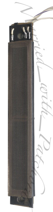
I am looking at an old moog ribbon controller and was curious if these can be used in a midi setup or possibly through the AIN connections on the core. It works on Micromoog, Multimoog, Polymoog and Liberation models terminates with a 3 prong connector.

-
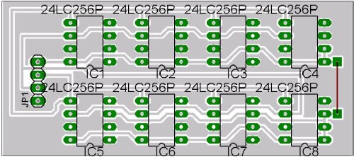
Thanks for the reply. So I guess banksticks can be mounted on 8 pin Dual sockets? Banksticks seem so small is there a special type of socket? Has any one ordered these before. I asked mike if I need anything else when I ordered but never got a reply. Mike Help me out! :P If I don't use sockets can I damage the bankstick when soldering?
-
What are the little numbers and holes right below the 3 digit bpm leds? Did I miss those extra funcitons?
-
You really do your homework stryd! Thanks for all your input! I am probably going for tact switches instead because I am getting some homemade caps. Good info for all boxers though!
-
What do you mean link the switch? I am looking at the omron b3f tactile switches 12x12mm that they have at rapid electronics. Does anyone know if these are "heavy feeling" switches? I noticed they weight 3x as much as the 6x6mm switches. They have a "Switching capacity is 1 to 50 mA, 5 to 24 VDC (resistive load)" The core sends more than 1ma to the switches right?
-
Thanks stryd! So all midibox cores only draw 5v from power supply which in turn send 5v to each button when pressed? I know you said that 24v dc 50ma switch should be ok but is it overkill concerning resistence or anything else? That type of switch is what I plan on getting.
-
Seq V3 - first LCD row black [solve]
Echopraxia replied to vincentime's topic in Testing/Troubleshooting
What I meant by pic header is the long strain of numbers 00 00 00 00 00 that are programmed into the pic. In MIOS Studio software, in the hex file upload window its the device ID. Both the device IDs have to match. Sorry if I used the wrong wording. When you buy your pics from smashtv he puts a device ID number on the pic for you. Did you get yours from smash or are you programming your own pic with bootstrap loader? I am not familiar with bootstrap loader because smash takes care of it for me ;D -
Seq V3 - first LCD row black [solve]
Echopraxia replied to vincentime's topic in Testing/Troubleshooting
I had the same "problem" with my first display I connected up to my core aswell. Concerning the upper black row TK said that this was normal when no application was running from the pic. Check the pic header number on the pic itself and in mios if you have trouble uploading. They should match. You should also try loading the most updated mios into the pic first before you upload the seq hex file. I am no expert but these steps worked for me on my SEQ v3.2. Goodluck. -
Does contact rating matter much when selecting switches? I am looking at rapid electronics omron b3f switches which have a contact rating of 24V DC 50mA. Does this have an effect on the whole power consumption of the midibox i.e ma rating of power supply? Would these draw alot of power? I see alot of switches with 12v DC. Do you know what the difference is between 12v and 24v switches?
-
I just got my bankstick pcbs from mike and I had a question. One side has the copper tracings and the other side is just plain bread board. My question is do the banksticks get placed on the bread board side ,then I flip the board over and solder the pins on the copper side correct? There is no nice legend like on smash's boards. I would hate to solder the banksticks on the wrong way. I don't need any dil sockets to mount the banksticks to the pcb right? Sorry that these are very simple questions which I should know by now but smash has spoiled me. ;D Also what are the pins to the right with the red line going down used for?

-
TK, on your MBSEQ 3.2 asm file, you mention "never change the origin". I want to change the din and douts shift register pinning so my cabling will be nice a straight inside my case. My question is which part do I change? Do I only change the SR# + pin# or do I move the function name to another line where the "correct" SR# + PIN# are? I basically want to have the track,pattern,layer and trigger dins to be on the first registers because all of those buttons are goinh to be on the left side of my case and my first din module is toward the left of the case aswell. I would hate to have a whole bunch of extra long cable inside the case.
-
If you want to get them to line up nicely, you're going to have to do a custom PCB, because they have usually have alignment pegs, as well as connector pins. So these switches won't mount to regular breadboard? If thats the case back to the drawing board. :-\ I might try sasha's very cool 3 piece acrylic button. It doesn't sound to hard. You just need acrylic cut to shape and sanded down,drilled and glued.
-
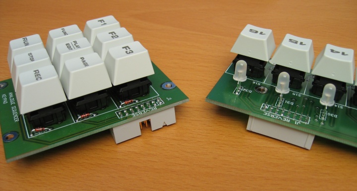
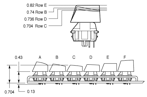
Sasha for your sequencer are you using encoders similar in height to smashtv's encoders? Are you mounting these buttons to the same breadboard as the encoders? I am wondering about the 6mm,4mm and 4mm pieces and if that combination is perfect for height from pcb to panel. On your sequencer how much of the buttons is sticking out above the front panel in mm height? ____---___
-
I was thinking the same thing about laser etching my key caps and the front panel. Do you think if paint the keycaps then add glossy clear coat then get them laser etched would be ok? Does anybody know where I can get laser etching done in small quantities?
-
I alos noticed this one.http://www.sequentix.com/build/cnst-switches.htm The guy will also sell you laser engraved caps with 1-16 on them. If he can do differnt color caps that would be awsome. I might not even care if the led is in the switch. Just thought I''d metion these. I may or may not go with these becasue I wanted to paint my caps. Thes caps also look like the same height as the type "E" deck was talking about.

-
Deck keyboards emailed me again and told me the blank caps they have are like the type "E" cylindrical ones on cherry's mx page. They are not really angled but do have a ramp towards the front. Here is the pic of the differnet angles. I think these would make a good combination to the switches because the company actually wants you to customize the blank caps and its only $20 for 80 qty caps. I.E paint the blank caps or whatever you can come up with. Deck also told me that the on the blank caps the led is going to shine mostly in the center of the cap. Sounds good to me. We just have to find a good/cheap distributor. SO far I found a place where you can get 250 qty of the soft tactile for $81 which comes out to about $0.33 a piece but NO LED and no caps. http://www.shopblt.com/index.shtml

-
I just checked my email and got a reply form the deck keyboard company http://www.deckkeyboards.com They told me they do use cherry mx switches for there keyboards. part number is MX1A-11NW. This part number indicates that their switches don't come with the leds stock but they put them on themselves. I belive its because they have their own diy community that likes to switch leds out on certain keys because people like their keyboards so much. Deck keyboards have a good reputation from what I hear. the part number would also indicate that they use the linear type. They other thing is they sell a bag of blank keycaps at their site which they say "The blank keycaps are not clear but let the light shine through" whatever that means? But they are probably not the standard 8mm caps and probably the angled ones. I will ask this.
-
power supply ma rating for fully equipped MBSEQ 3.2
Echopraxia replied to Echopraxia's topic in MIDIbox SEQ
The lcds are backlit! Should I get a new power supply with a higher ma rating before trying to connect all the buttons and encoders? I just have both lcds and the core powered up right now and it works like a charm. What ma rating would you recommend? I read somewhere that as long as you stay under 1 amp you'll be ok? Is this true? -
I emailed cherry for some samples. I hope they actualy do it. I requested 1 of each led color for the linear and soft-tactile switches pcb mount. They have green, red and yellow. I also requested some standard 8mm caps (not the angled ones).They did not specify what color are the caps but I asked if they can do black. I will let you know if I get them and I will post pics when and if that happens. I am still not sure how the leds light the caps up so I asked them how that works aswell.
-
I haven't settled on anything. They talk the talk but samples would be good. Some where I read life expectancy is very high. I think these are the same type as in the deck keyboards that sell for $99 but I am not 100% sure on that. I don't like clicky buttons either so I think samples of soft tactile and regular are in order. I can't find a picture of these keys with the led on. For caps I think the best would be the flat ones in the datasheet. I am alittle behind on my project right now and short on cash to organize the order but between both of us I thuink we can do it and get a good deal.
-
Any one interested in this switch? They seem like very good quality and are about $50 with caps but without leds from digikey for 50 qty. I am trying to find another seller that can do the ones with LEDs. The ones I would like to get are soft-tactile pcb mount with red leds. What is the preference on soft-tactile and regular tactile? I don't know the difference between the two? Any info on these would be appreciated. One more question. Does anybody know if these can be mounted to the same pcb/board as smash's encoders and get an even/balanced height?
-
2-pin female crimp connectors for 2.54mm pins
Echopraxia replied to miggyb's topic in Parts Questions
Back again. I got my sil housings and crimps tyco cst series. When I push the crimp into the housing, it goes in but it is able to move up and down about 1-2mm inside the housing. Is this normal? Ultra I followed everything you said except that I crimped both parts of the crimp connector (part with insulated wire and part with bare wire). Then I soldered the crimped bare wire. Did I mess up on these or is this workable? Will they break on me or something later on because I crimped the bare wire part? These connectors seem very nice but I still think idc is more stable/strong at the moment. Does anybody make 1,2,3,4,5 pin idc connectors? -
Will the 9v 500 ma suggested power supply still be enough for the MBSEQ 3.2 with all the extra buttons and leds along with at least 2 IIC modules, 8 banksticks and both LCDs? Would it fall under 500ma or go above?
-
Well I used no clean solder and I am very happy with it but I bought some crappy radio shack wick which left some brown stuff on the board when I had to desolder anything. I got some better wick right away but I already made a couple modules while using the radio shack brand. The other boards look fine but still have that clear goo around the joints.