Smithy
-
Posts
1,240 -
Joined
-
Last visited
-
Days Won
28
Content Type
Profiles
Forums
Blogs
Gallery
Everything posted by Smithy
-
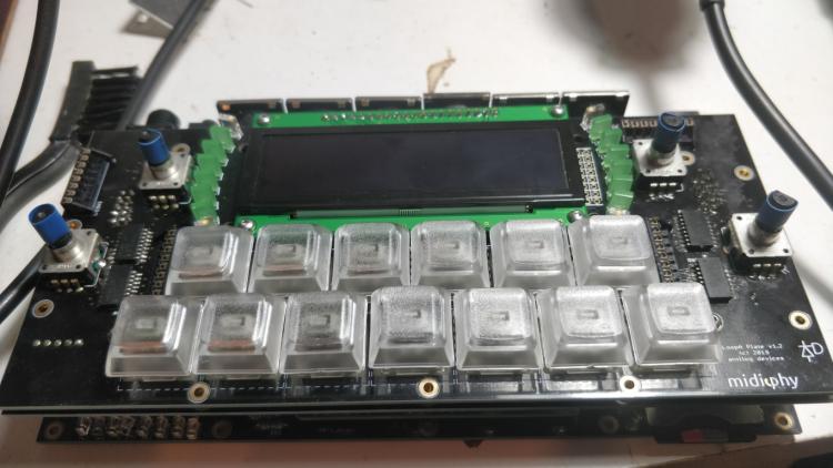
Success! I inserted a pin from a header into the Cathode hole for the LED and used a crocodile clip to jumper the leg of the switch to it and all 3 switches work. :) So in my case I didn't need to solder the switches first. Going to insert the LEDs now and solder them in. Edit- actually the RJ and SJ resistors are next. OLEDs are working also (even though thats later on in the guide). I'm waiting on shielded MIDI sockets to arrive from Post NL so I won't be finished til I receive them but I'm pretty (Thorsten) klose to finishing it. ;)
-
Just checked the Erata for that pcb on the wiki and it says: The C3 cathode row is missing a PCB trace. Join the two legs of SW19 as shown in pink, preferably on the bottom of the PCB. The LED cathode leg could simply be bent across to the switch pin. http://www.midibox.org/dokuwiki/doku.php?id=seqv4plus_le_mec Will give this a go!
-
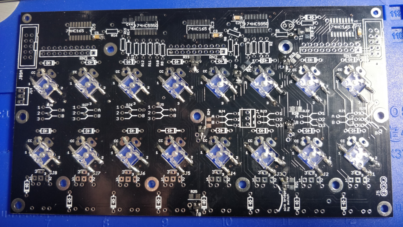
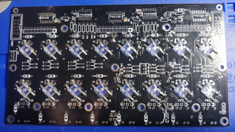
Ordered and installed longer 3M headers from farnell, they have the same height above the plastic where the the enter the shrouded header, but longer on the otherside but since this is cut at the joints it works out perfectly. I'm at the stage where I'm testing the DIN switch function and SW17, SW18 and S20 on the left LE MEC 1.0 PCB are unresponsive in the MIOS terminal. All other switches including SW19 and the Encoder switches work fine giving the correct debug messages. All switches are pushed in and are not soldered yet. Have them connected to the ENC-Plate 1.0 PCBs but these probably have nothing to do with my issue. Pat_00 had a similar issue previously in the thread, but R3 seems okay to me: Here's the view of the bottom of the LEMEC PCB: Any ideas which components might be responsible? Btw theres a lot of flux on the board from piggybacking the BAT54 diodes on the transistors. Its a no clean flux according to the Kester manual. Thanks again!
-
Ah I get you now! Thanks a lot for the help Andy!
-
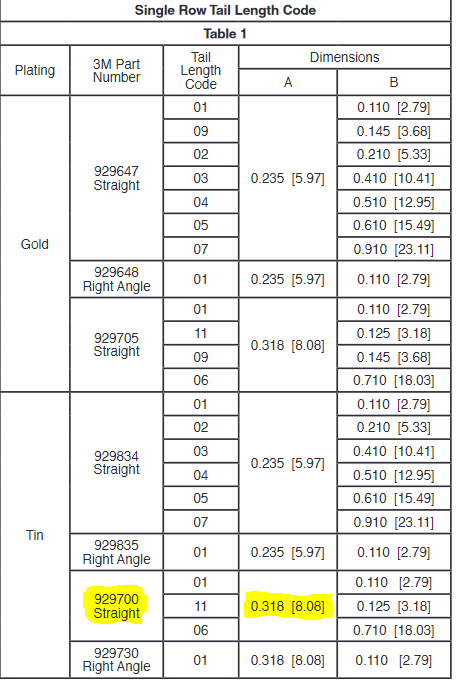
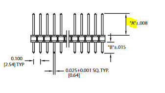
So the length of the "mating pin" / Dimension "B" is actually 6.8mm? I thought from original 3M datasheet it was 8.08mm / 0.318" freedom units ;) based on the codes: Dimension A in the original 3M datasheet btw. I have standard headers which are 6MM long on top btw.

-
Here's the Isolated Resistor Network also on RS: https://ie.rs-online.com/web/p/resistor-networks-resistor-arrays/7884066/
-
Haha not 3 on top of each other no! I'm short 2 components from the BOM, they may have not been finalized when I orderered back in the stone age as Peter would say! ;) I'm short the 4816P-1-103LF Resistor network for RN5 on the LE MEC RH PCB so I presume its needed? Also i'm missing 929700-01-36-RK - the longer Pin headers. I believe these need to be about 8mm long from the top of the plastic to the top of the Pin itself (when standing upright). I think I've found some equivalents on RS, could you double check Andy if you dont mind? https://ie.rs-online.com/web/p/pcb-headers/6812310/ I'm going by dimension "B" in the datasheet: https://docs.rs-online.com/36e1/0900766b8135fed6.pdf
-
Thanks for the prompt replies! I must be insane (I guess we all know that right? ;) ) As I have went ahead and soldered 3 bat54 diodes on top of the BC818s. It's not easy getting the solder to reach the pins of the diodes but I'm getting there! 5 more to go.
-
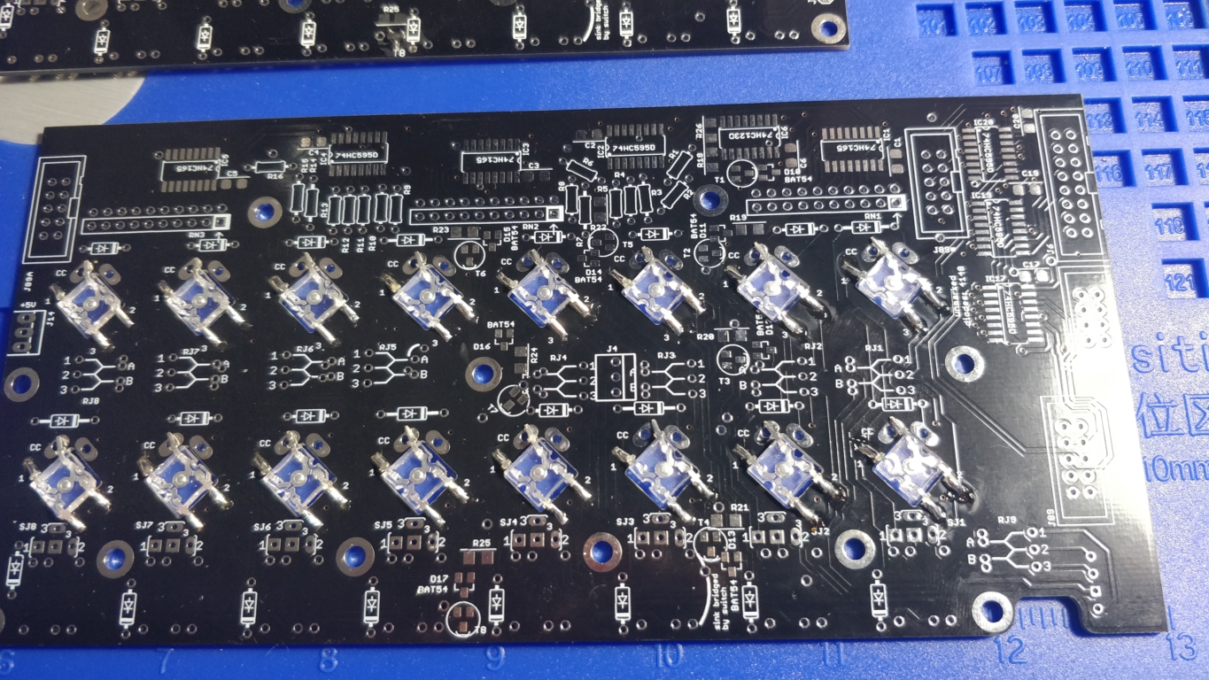
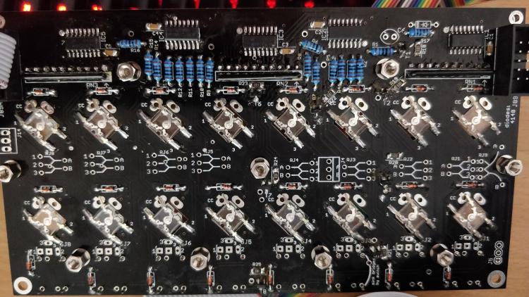
Something has me stumped with the build guide video part @ 58 mins Peter is soldering BAT54 diodes to the LeMEC pcb. I don't have any markings for BAT54 diodes on my LeMEC pcb. My PCB version is 1.0. I only have markings for BAT54 diodes on LeMEC RH PCB of which I have version 1.3_R. Here is the LeMEC pcb I have with the backside showing: And heres the backside of the LeMEC RH PCB Is it okay to ignore the bat54 diodes on the LeMEC board and proceed? Thanks.

-
Can't believe I lucked out! I usually use a temp of 350 degrees C for soldering including drag soldering. After this I would recommend using a temp closer to 300 degrees for SMT parts! Thanks a lot for your help Andy. The encoder, switches and LEDs are working beautifully.
-
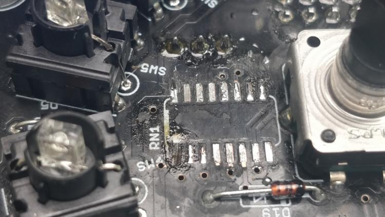
So I removed the chip fine but ended up lifting the pad for pin 1 when trying to solder the correct 10k resistor network. I had problems getting the solder to take to that pad when aligning the chip - I should have used the chisel tip instead of the bevel to apply solder to the corner pads first.I usually only use the bevel tip for drag soldering. I applied some flux also and that must have been enough to lift the pad. Is there anywhere I can solder a bridge between pin 1 and a pad it connects to?
-
Sort of answered my own question there. If anyone has any advice on how to desolder the chip, what temperature to use, should I use flux or solder paste, it would be great. I also have kapton tape for nearby components.
-
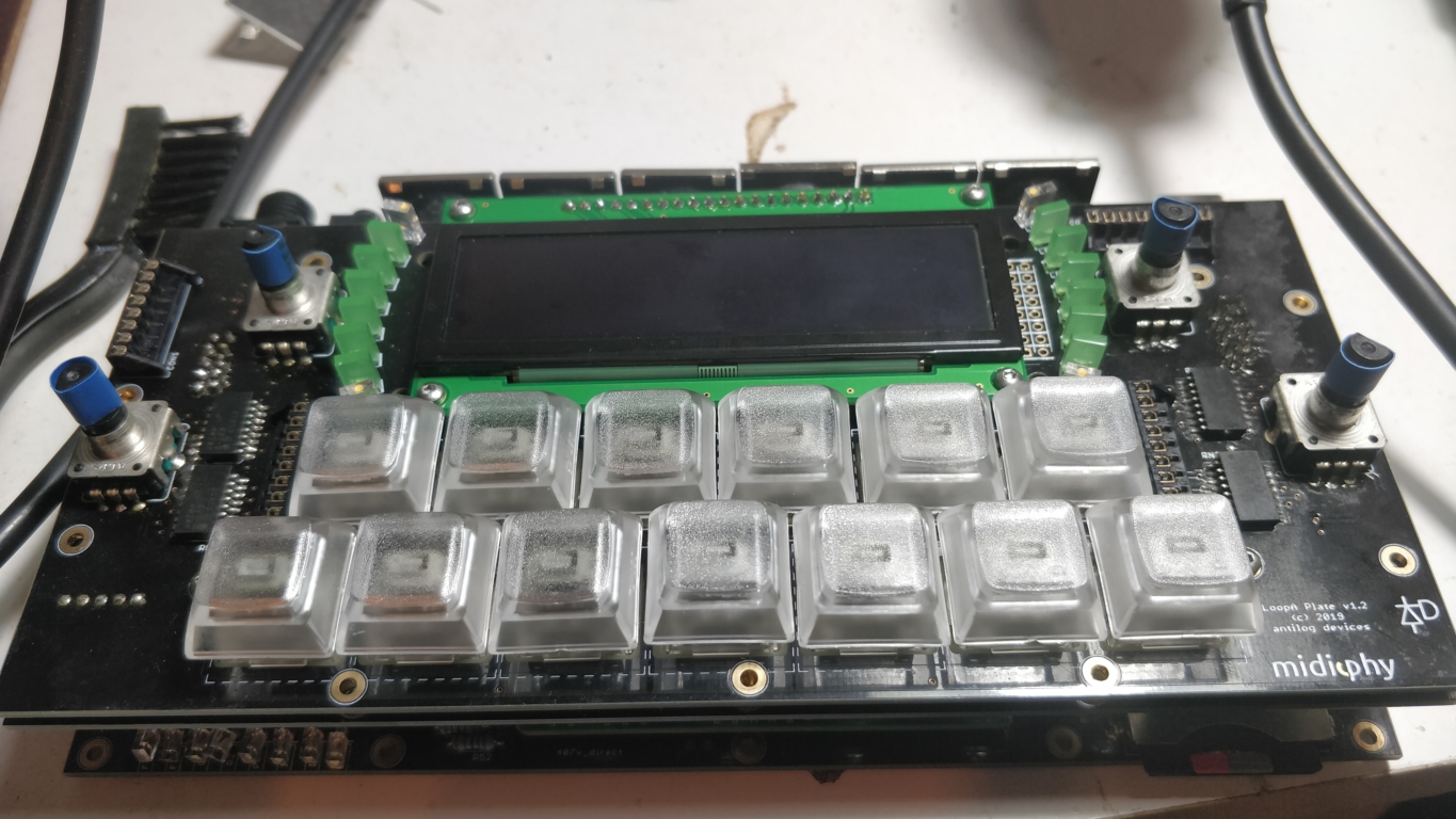
So I've been getting erratic behavior with the LEDs on the switches of the JA PCB. I wonder if i made the same mistake soldering the wrong type resistor network? The markings on the IC at RN1 are 4816P LF1-103 C1809 instead of 4816P-T02-103LF. I blame myself for not checking the BOM on midiphy and solely relying on the video! Thankfully i have a hot air station, flux and solder paste so should be able to remedy this issue.
-
Congrats Andy! I've decided to resume my SEQ v4+ build tonight so your "betatester" should finally have it finished soon too!
-
Thanks SSP. The cutting came out great! Well done! Hell I'd even label it manually myself if needs be. Let me know if you have any suggestions. Thanks a million, Smithy.
-
Hey SSP, thanks for reaching out and apologies for the late reply! I would definitely be interested in paying you for a laser cut acrylic front panel. The one slight catch is I need the engraved text to be legible with a high contrast to the rest of the panel. Is it possible that you could use Cast Acrylic at work for this? Or a two tone acrylic e.g. black acrylic with a white core? I am trying to avoid infilling the engraved acrylic with paint manually. As you can see, the original acrylic case for the midiphy loopA for example is difficult to read even in well lit conditions: http://midibox.org/forums/topic/20833-loopa-v2-introduction-features-support-thread/ The cast acrylic would be well illuminated with the high amount of LEDs in the panel also. Which country are you based in by the way? Please find the dxf file attached and the original fpd file it was exported from. Thanks for your time, Smithy. mbqg_fp_modledrings Updated Case Holes.dxf mbqg_fp_modledrings Updated Case Holes.fpd
-
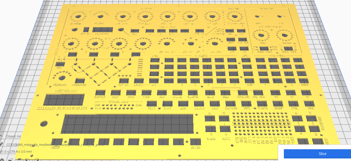
[3D Printable Front Panel File for use by Wiki] mbqg_fp_modledrings_Holes_Moved_ready_to_print.zip Attached is an STL file of the front panel with raised lettering for use with 3D Printing To produce a bi-coloured panel with a different colour for the lettering please follow this easy guide: This file is provided as a lower cost method for producing a 3D printed front panel as opposed the cost of having an alluminium panel milled by Schaeffer which costs 410 euro in the EU excluding shipping. However, it may be better to use an SVG file to have acrylic laser cut, which will be cheaper to order online and have more accurate cuts and engravings. I have an SVG file ready and working with the Formular.de ordering system, but it is not currently compatible with Ponokos ordering system so I have emailed them. I will update the thread if I make any progress with Ponoko. Here's a preview of the 3D Printable STL file:

-
Here are some additional 3D Models / STL files for the Buttons and Light pipes converted to the metric system for 2mm Panels: mbqg_fp_buttons converted to mm for 2mm panel.stl mbqg_fp_ledpipes converted to mm for 2mm panel.stl And these files are for 3mm panels with the appropriate mesh extruded / lengthened. mbqg_fp_buttons converted to mm for 3mm panel.stl mbqg_fp_ledpipes converted to mm for 3mm panel.stl
-
 Here's a tip for anyone who wants an easy way of having raised lettering on their 3D prints with a different colour to the case itself. Print the case with lettering with the same colour filament you want the raised lettering to have. Paint or (spray paint is probably best) the entire case in the colour you want the case to be. Then simply sand the lettering with sand paper and the original filament colour will come through. I saw this method posted in a facebook Flight Sim group where a user 3D printed his own Boeing 737 panels:
 -
Here's a tip for anyone who wants an easy way of having raised lettering on their 3D prints with a different colour to the case itself. Print the case with lettering with the same colour filament you want the raised lettering to have. Paint or (spray paint is probably best) the entire case in the colour you want the case to be. Then simply sand the lettering with sand paper and the original filament colour will come through. I saw this method posted in a facebook Flight Sim group where a user 3D printed his own Boeing 737 panels:
-
User BEBDigital Audio kindly uploaded files for a 3D Printed case 6 days ago, just in case you guys are subscribed to this thread:
-
Excellent work! Very clean looking.
-
LoopA V2 Introduction, Features & Support Thread
Smithy replied to Hawkeye's topic in MIDIbox User Projects
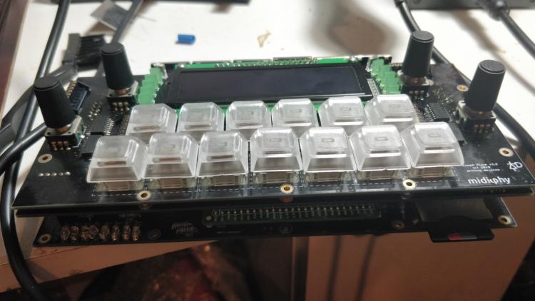
Congratulations on your hard work everyone involved! Nice to see a MIDIbox device finally get the recognition it deserves! I just wanted to update the thread and say that I had the intermittent booting issue since I built my LoopA and since installing those 2 resistors Andy suggested, it has been flawless! Such a fun little device to get ideas down quickly while remaining inspired and in the moment! One of the most important things for my workflow! -
Had a lot of fun of making this Live Cover of Anthony Rothers classic electro banger - Little Computer People. Used the midiphy LoopA to sequence and live loop this one. All the gear used is mentioned at the end of the video. I'm still recovering from surgery on my neck so the vocoder could be stronger. Enjoy.
-
LoopA V2 Introduction, Features & Support Thread
Smithy replied to Hawkeye's topic in MIDIbox User Projects
Updated my post above as the heatshrink was getting in the way of pushing down 1 or 2 knobs. I might try Kapton tape instead now.