

Smithy
-
Posts
1,240 -
Joined
-
Last visited
-
Days Won
28
Content Type
Profiles
Forums
Blogs
Gallery
Everything posted by Smithy
-
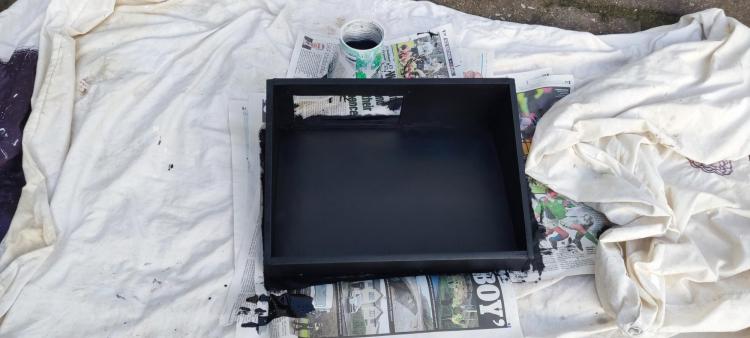
Bonus Step C: Painting the Case I used Rustins Matt Black Emulsion Paint for painting the case, as it's water based and will treat the MDF wood well. The 250ml tin would be more than enough for the case. Be sure to stir it very well in the tin before applying it. I used a combination of a mohair roller for covering most of the case and a small brush to fill in the corners.
-
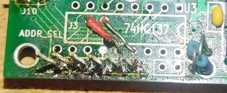
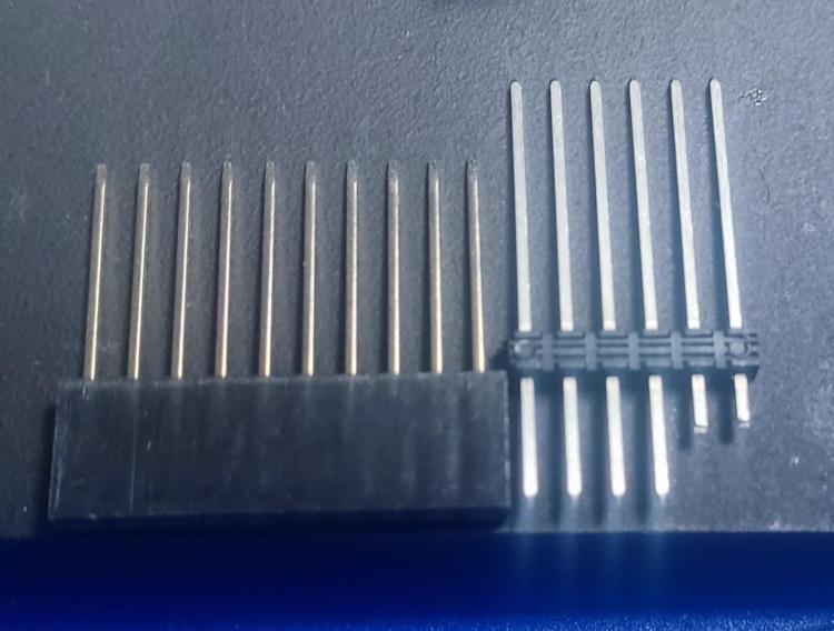
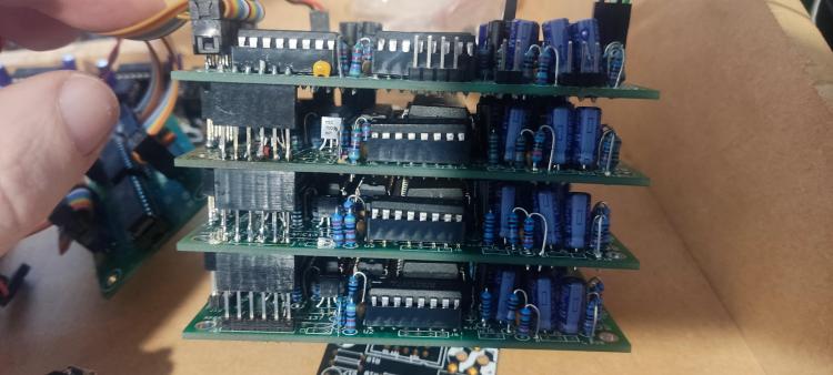
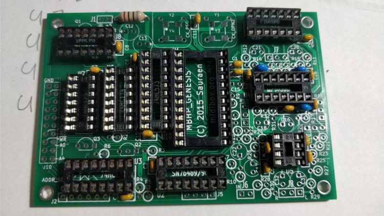
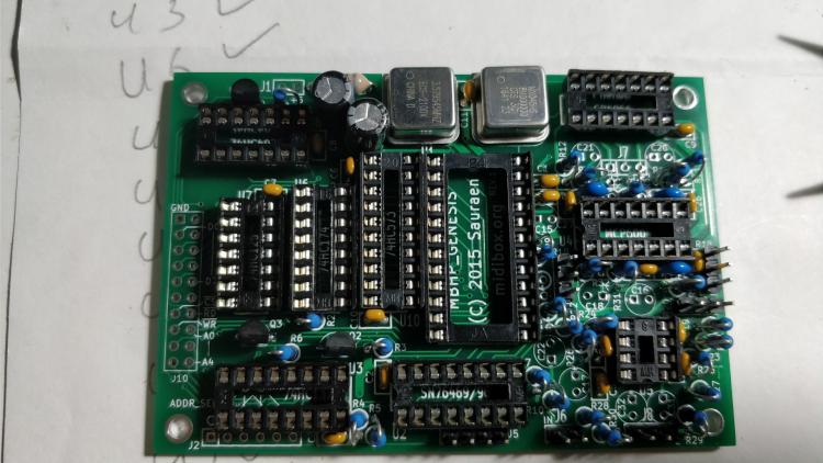
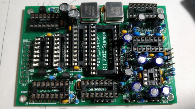
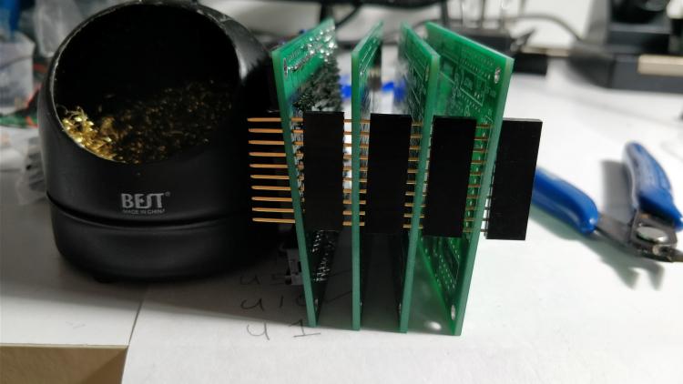
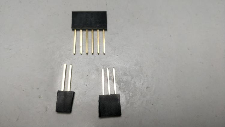
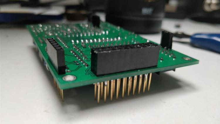
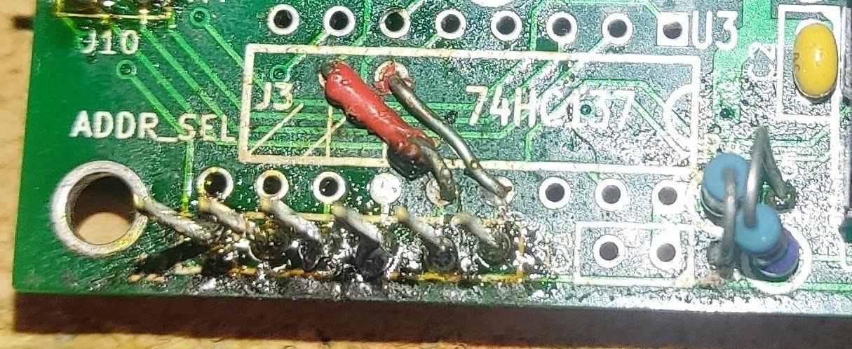
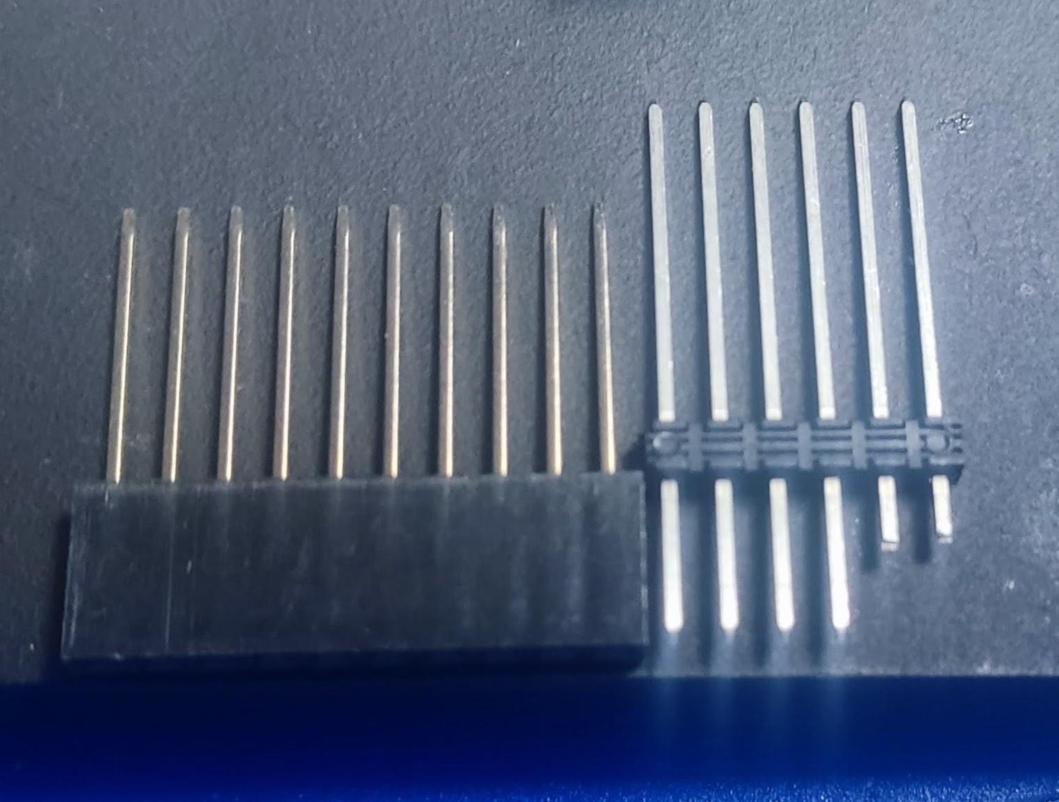
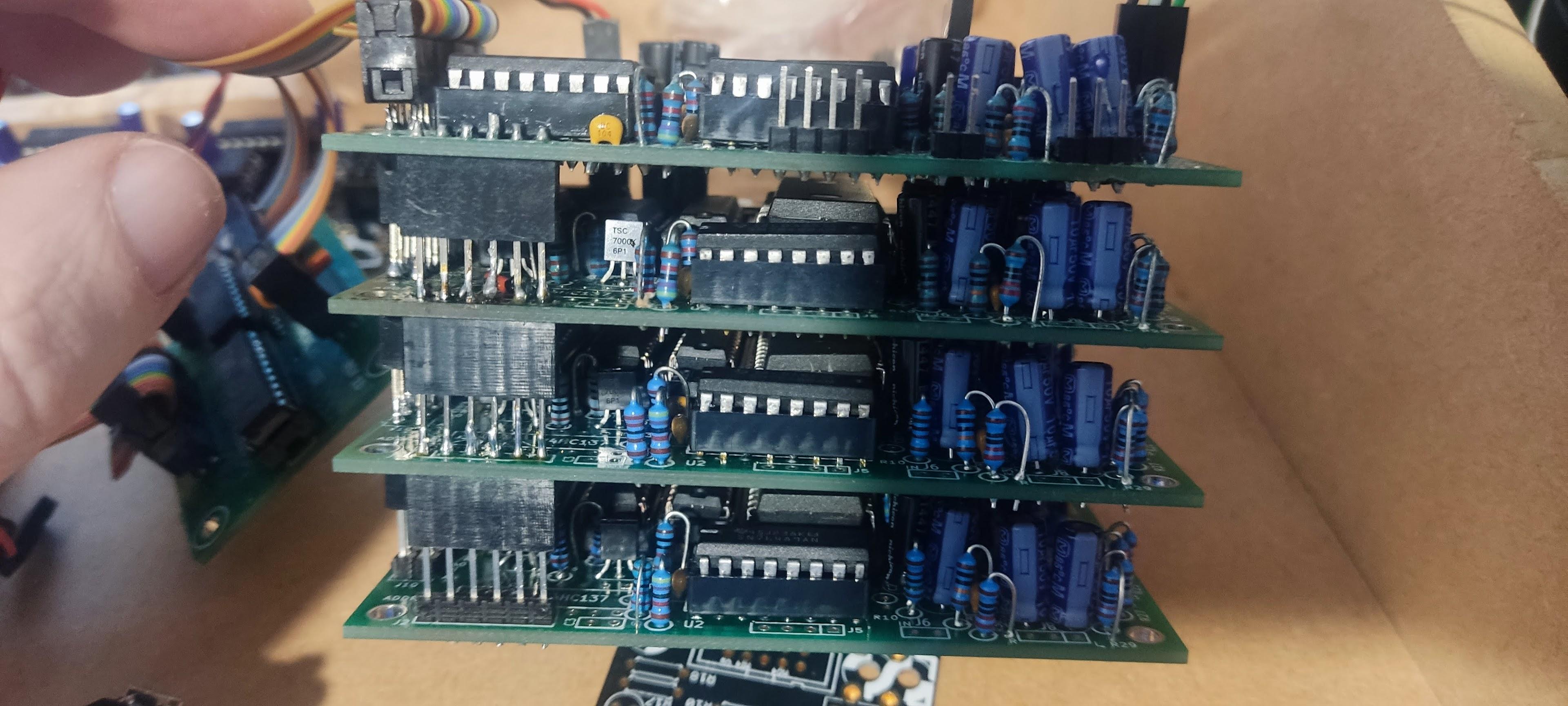
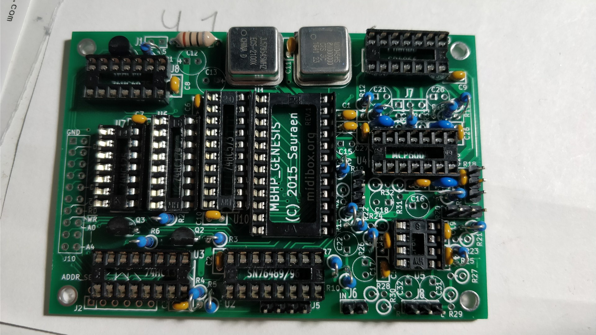
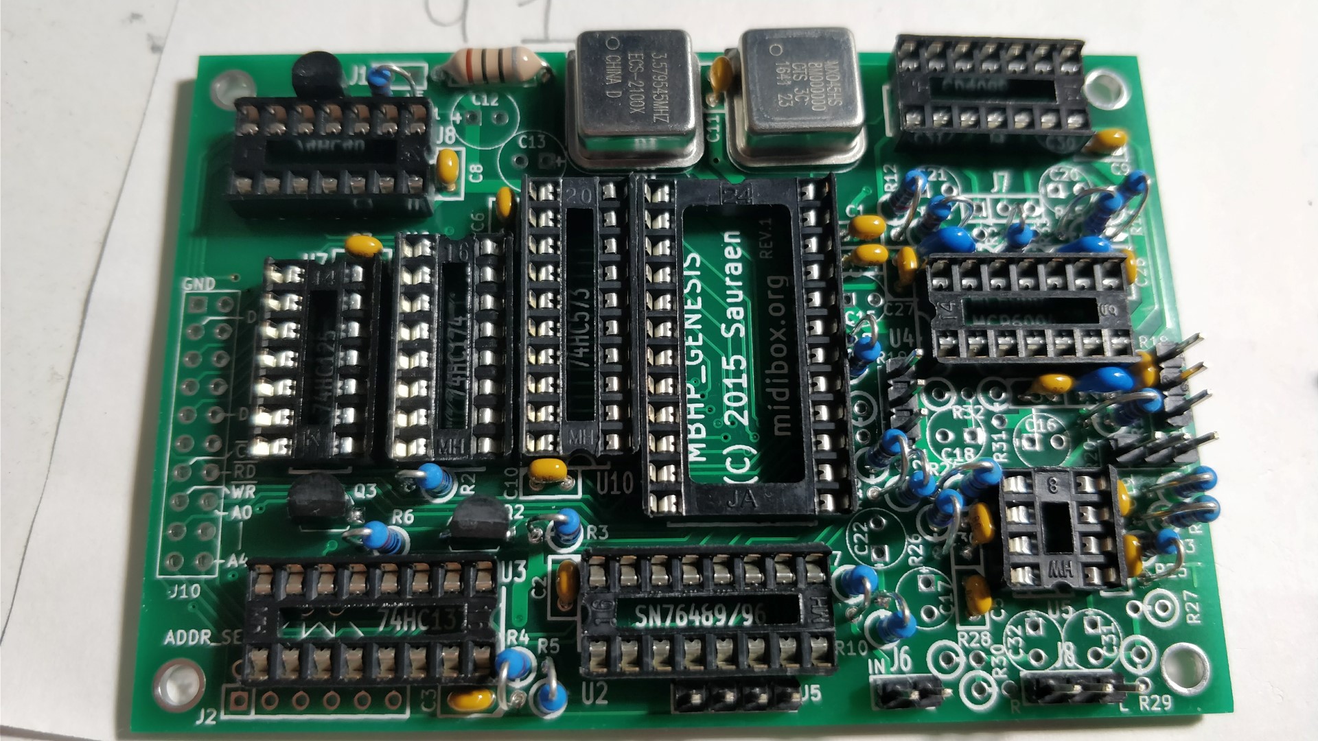
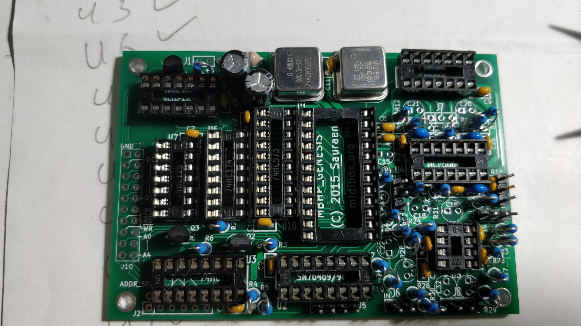
Soldering the remaining 3 MBHP_Genesis Boards. Now we will solder the necessary components for the 2nd Genesis Module PCB. Please follow the component stuff chart in the wiki. On board 2, don't stuff U3 or C3, but connect two wires on the top of the board, one from U3:13 to J3:2, and one from U3:12 to J3:1. They should follow the first two angled lines on the footprint for J3 under U3. Then we will solder the components starting with the shortest and working our way upto the highest like we did in the First Genesis Module. Omit C3, U3, U4, U5 U9. and headers J5,J6, J8, R18, R19, R20 And solder the components like we did for the first Genesis pcs again. Please note that we need to use the Extra Long Arduino headers with 15mm long pins in J1,J2 J7, J10. J1 needs 2 pins, J2 needs 6 pins, J7 needs 3 pins and J10 needs 20 pins i.e. 2 rows of 10 pins each. Push the Arduino header pins through the bottom of the board so that the female headers (black plastic) are underneath the pcb. As you can see we omitted the IC chips, U3, U4, U5, and U9. You do not need to solder the IC sockets either, there was a mistake in the Component stuff chart when I soldered these. Soldering the 3rd Genesis Module PCB: On board 3, same thing but connect U3:11 to J3:2 and U3:10 to J3:1. These two wires should follow the second set of lines on the board, the non-angled ones. They go straight down in this case. Omit C3, U3, U4, U5 U9. and headers J5,J6, J8, R18, R19, R20 And solder the components and headers like we did for the second Genesis PCB again. Soldering the 4TH Genesis Module PCB: On board 4, same thing but connect U3:9 to J3:2 and J3:3 to J3:1. These two wires should follow the last pair of lines on the board, angled in the opposite direction. Omit C3, U3, U4, U5 U9. and headers J5,J6, J8, R18, R19, R20 And solder the components like we did for the second and third Genesis PCB again. Stuff the components in order of height like the first Genesis Module PCB and stop before soldering the headers. For the headers this time we will use long SIL Headers with the black plastic on top of the 4th Genesis Module PCB. J1 needs 2 pins, J2 needs 6 pins, J7 needs 3 pins and J10 needs 20 pins i.e. 2 rows of 10 pins each. I used these SIL headers which were too long so I measured them against a spare Arduino Header as used in Genesis Module PCBs 1,2 and 3. (Please ignore the last 2 pins cut pins underneath the plastic) And then cut the upper pins height the same as 15mm long Arduino header. When soldered and connected all 4 boards should look like this:

.thumb.jpg.c76c1d9aaed7d604725633a4e2de46c1.jpg)
-
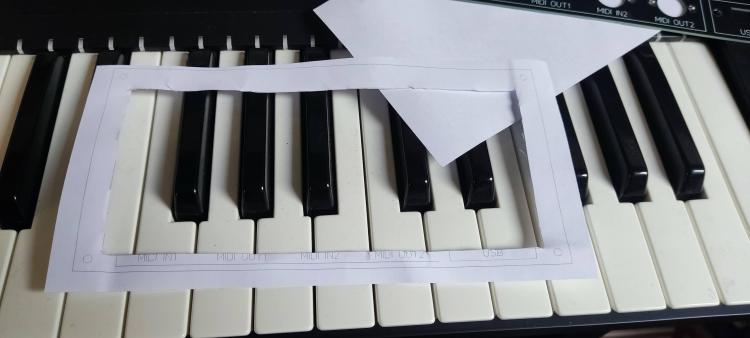
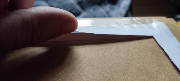
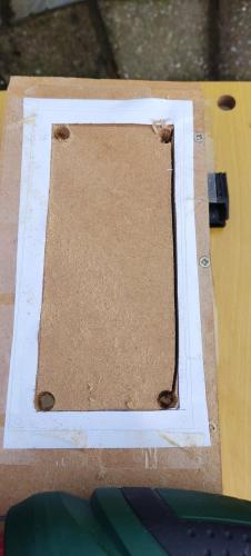
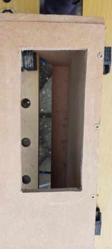
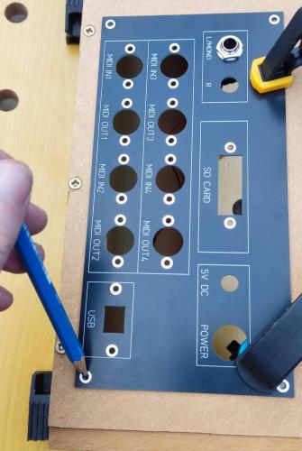
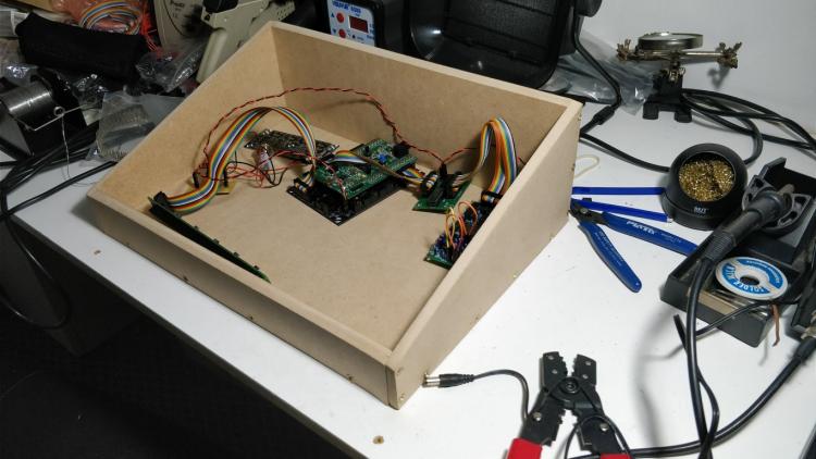
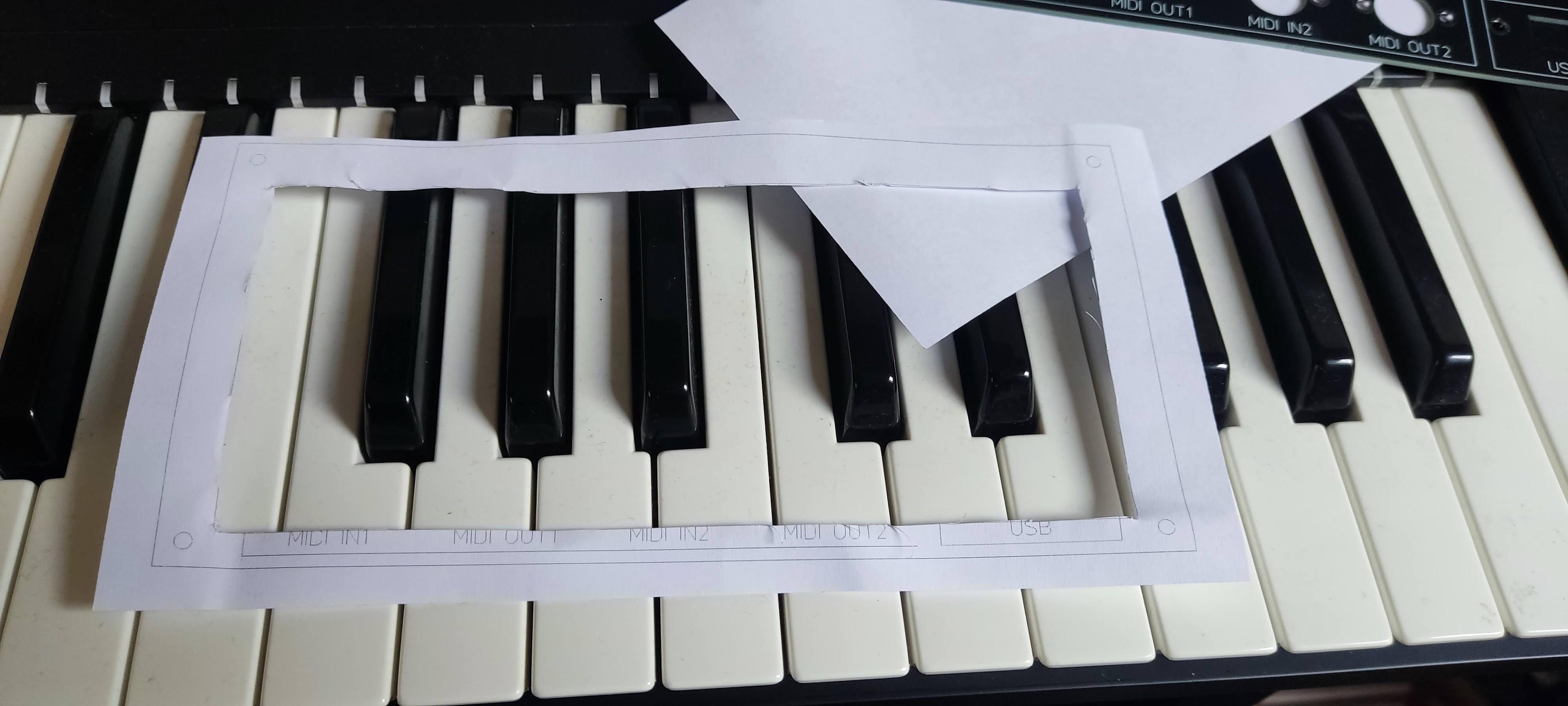
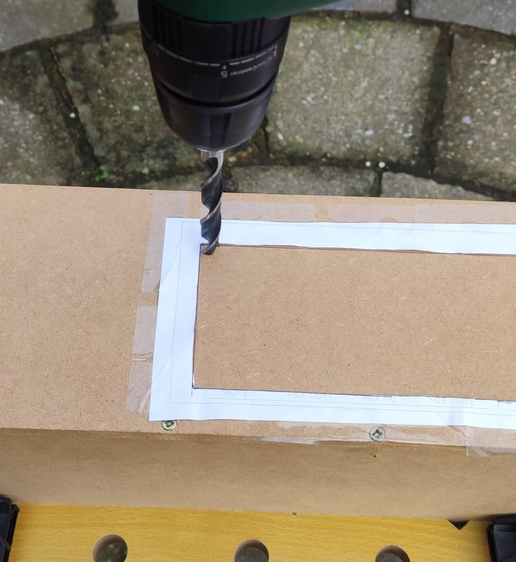
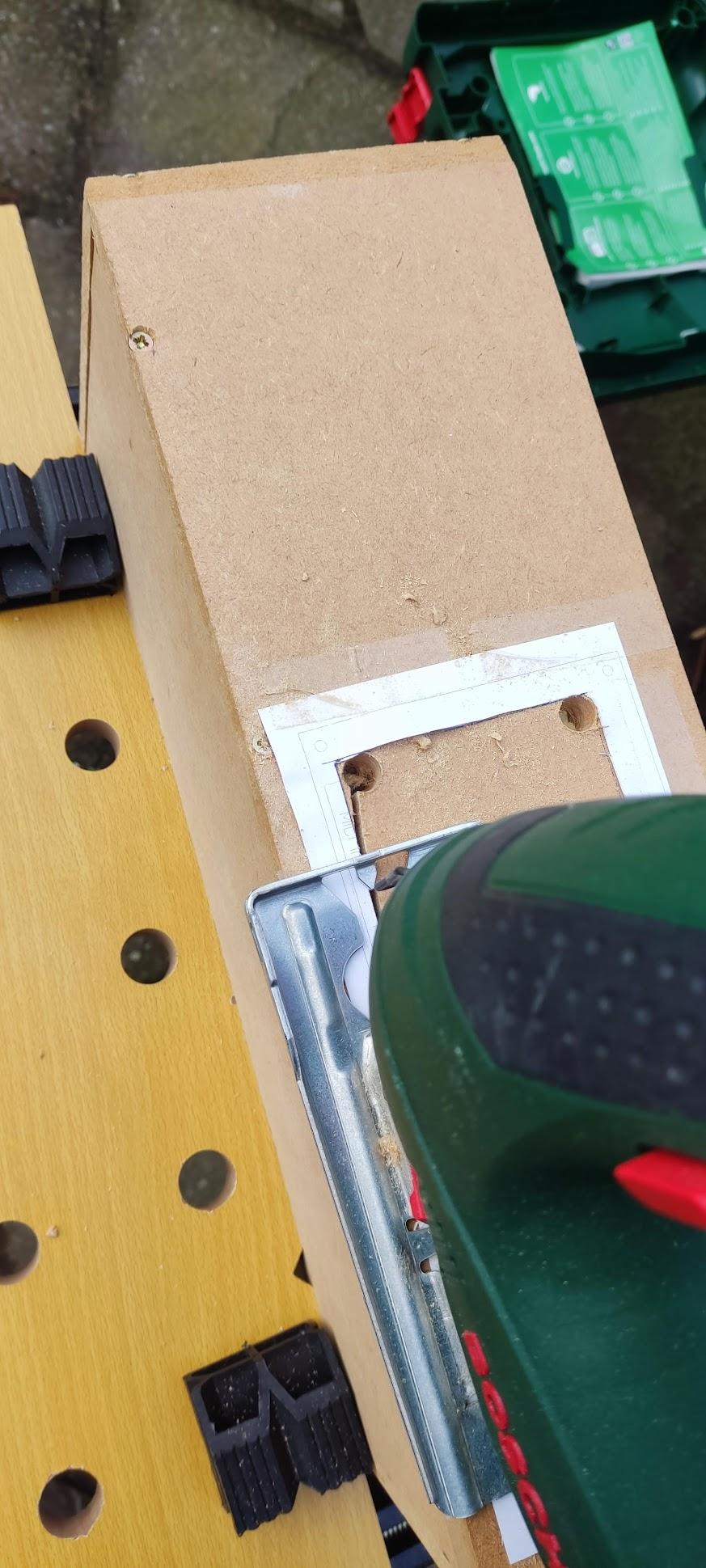
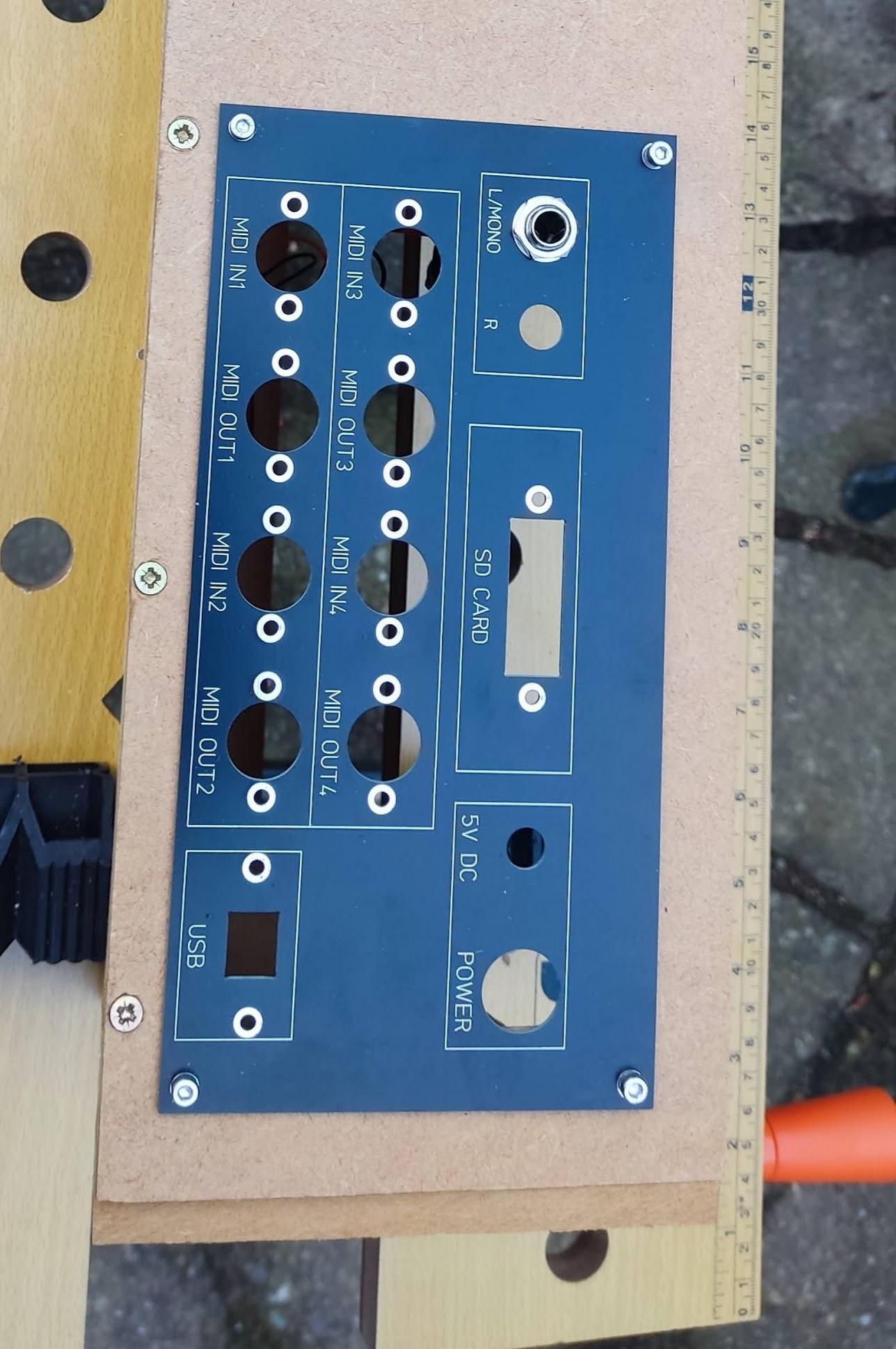
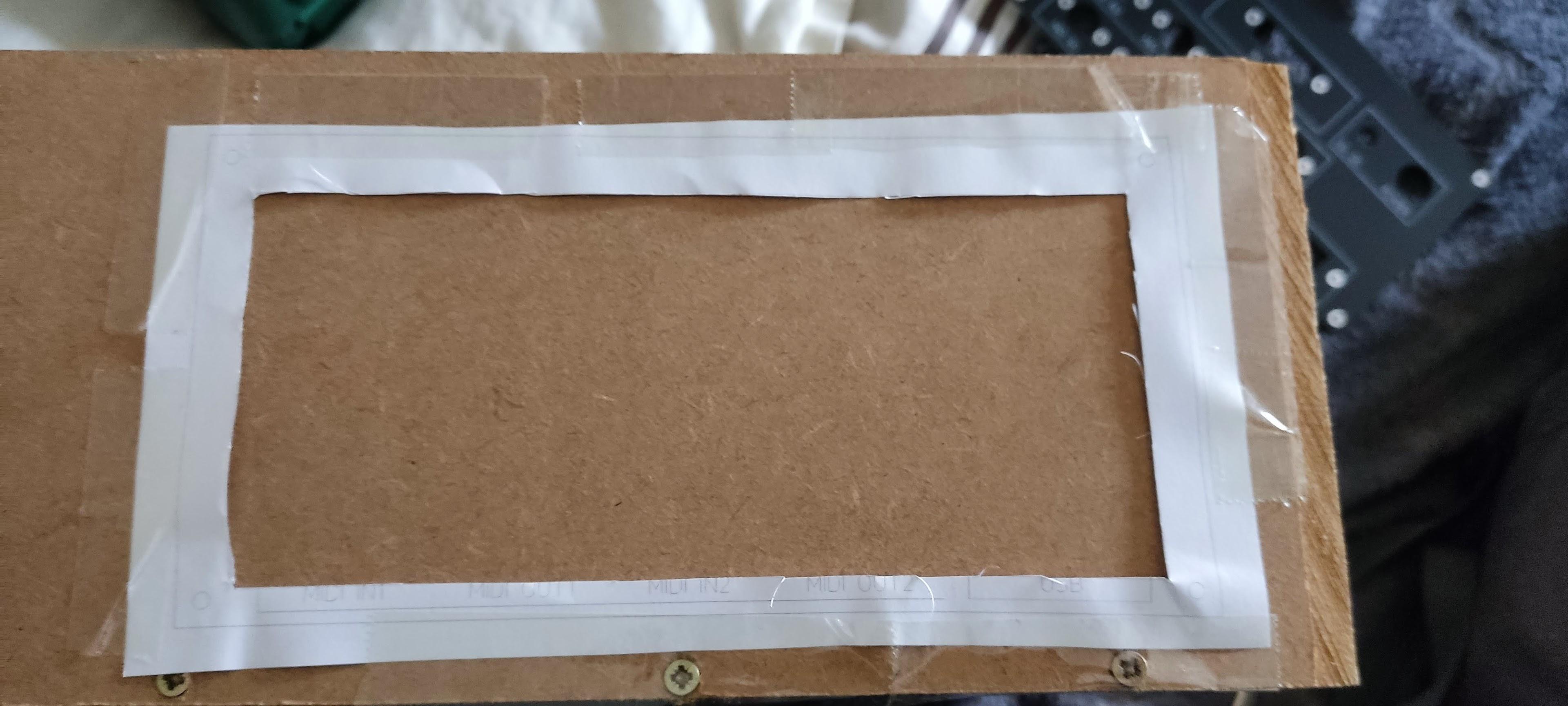
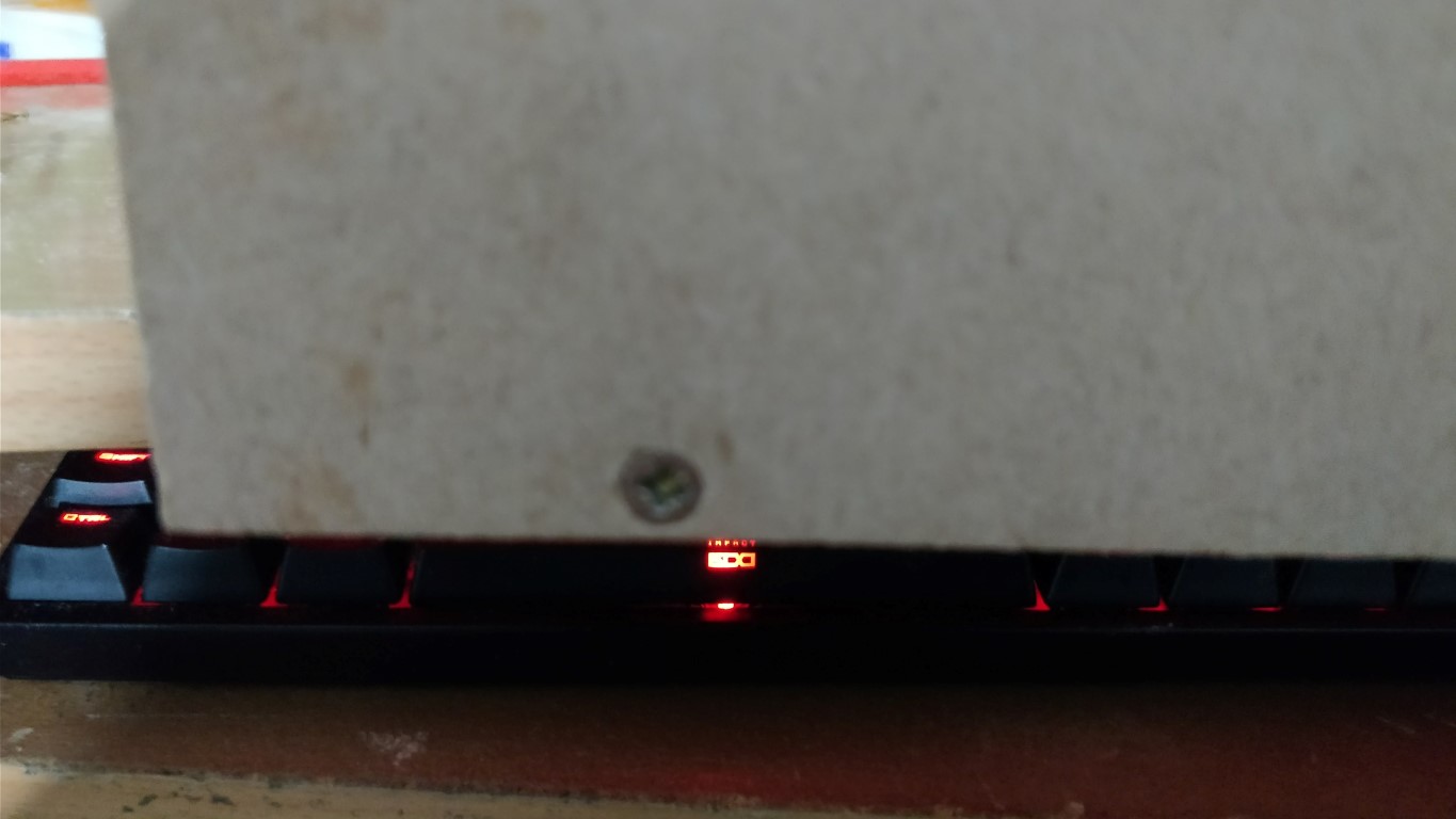
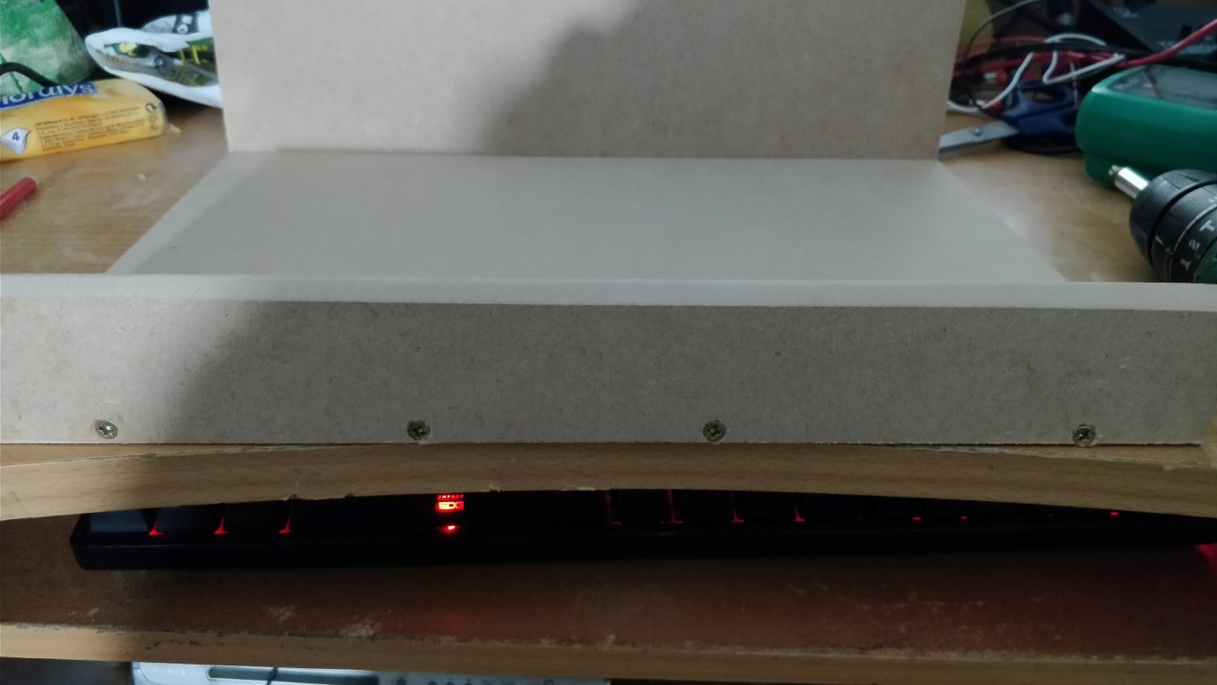
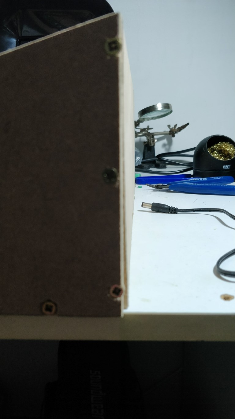
Making a Cutout in the Back Panel for an Alluminium / PCB panel with I/Os. You will need a Drill, 10mm~ Bit for Wood, a Jigsaw OR a hacksaw for cutting out the hole in the back of the case. And a 3mm wood bit for drilling the mounting holes for the Rear Panel. C clamps will be handy also. The drill bit will need to be large enough for you to fit the blade of the Jigsaw or Hacksaw into. I simply drew a rectangle on the Rear Panel file in Front Panel Desginer for where I wanted cutout, ensuring enough clearance for all panel mount components. Here is the file: Rear Panel with Rectangular cutout.fpd Then I printed the rear panel file from Front Panel Desginer, and cut out the rectangle I made. The template came out slightly smaller on paper than the actual rear panel even though I think I printed at 100% scale, but there was still enough clearance. I taped the template onto the back of the wooden case: I used a ruler to draw the rectangle on the wood also, as I was worried when cutting the paper would move but it actually stayed in place. I then mounted the case on my work bench, and drilled 4x 10mm holes in the corners, enough for my Jigsaws blade to fit through: So for my first cut I put the jigsaw into the bottom right hole and sawed at an angle and then turned the jigsaw a little to left when it met the line, and sawed up as far as the top right hole and stopped at the perpendicular line: I then turned my body 180 degrees and sawed the opposite way to cut the little piece of wood that was left from starting the cut: You can repeat this back and forth action for the other sides of the cutout and you should be left with something like this: If the cutout is not perfectly straight do not worry, you can use a coarse file or sand paper to straighten it out. Thanks @technobreathfor the suggestion to use a file. Next we will put the rear panel on the back of the case, ensuring its perfectly level, I used C clamps to hold it in place. Now draw through the mounting holes with a pencil: Remove the rear panel and drill your 4 holes with a 3mm Drill bit. You can now mount the Rear Panel using 4x M3 bolts with a screw length of 16mm preferably, an m3 washer for between the rear panel and the head of the bolt, an m3 washer on the inside of the case between the wood and an m3 nut.


.thumb.jpg.2d5a352d8ed3f03882b9678b09d3611f.jpg)

-
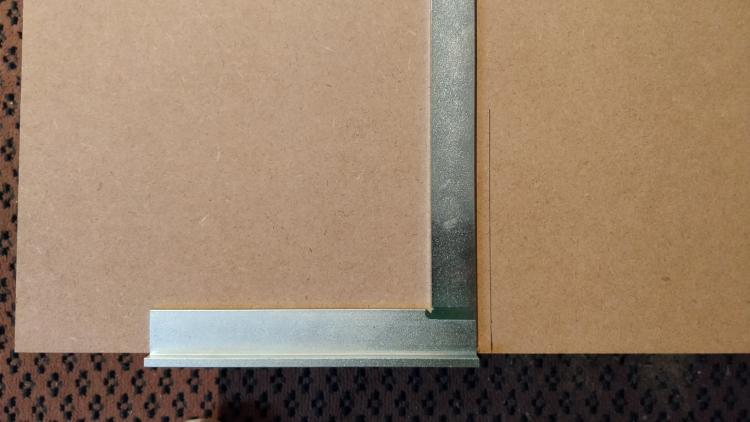
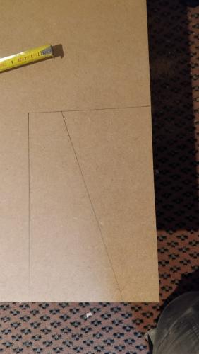
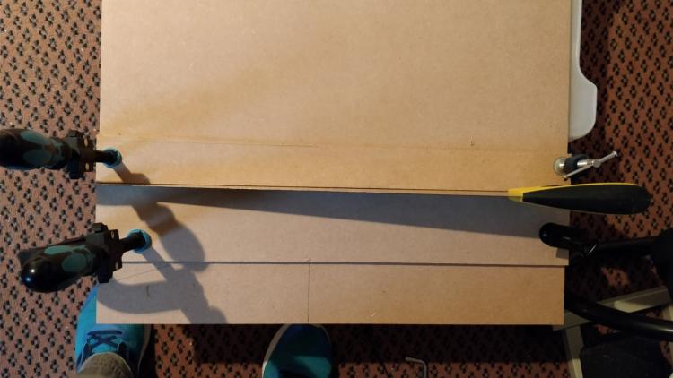
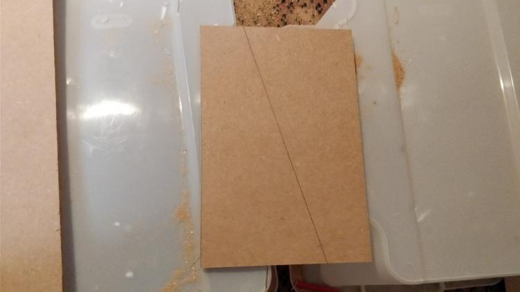
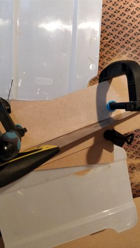
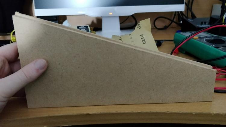
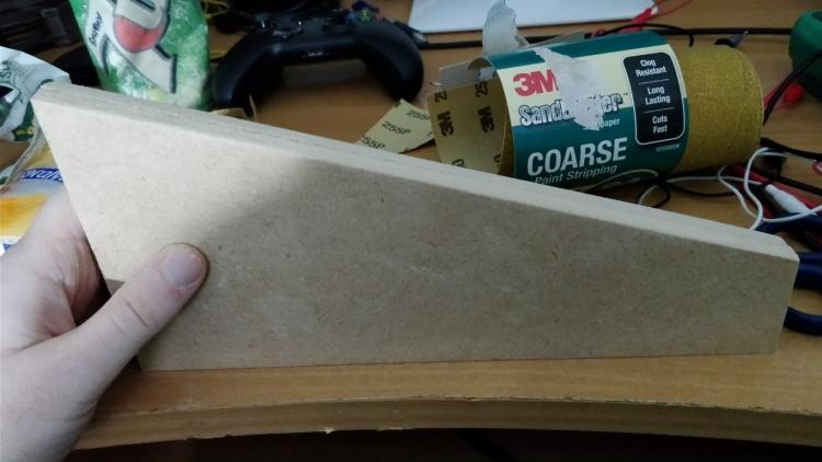
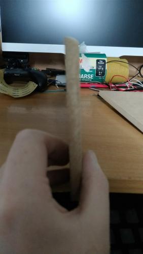
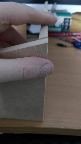
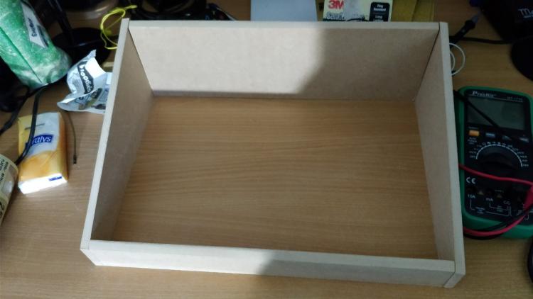
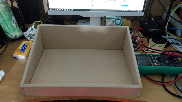
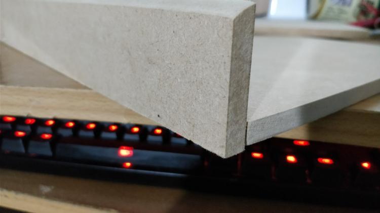
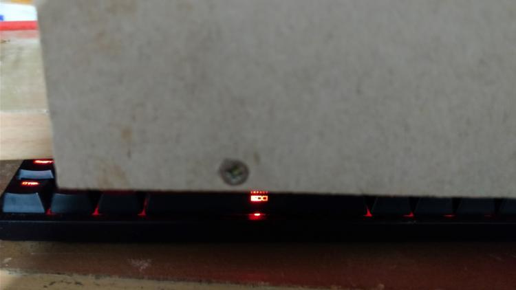
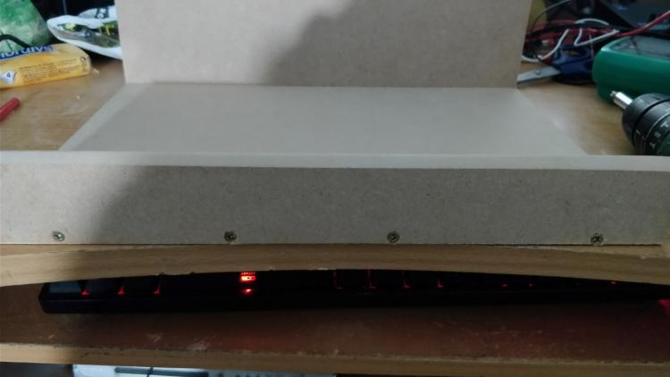
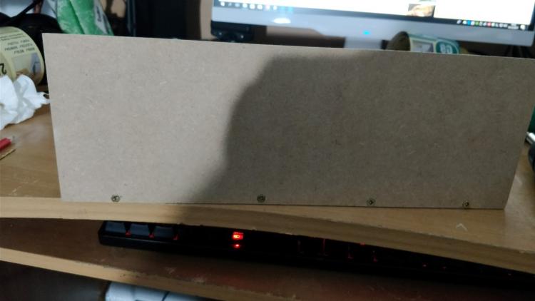
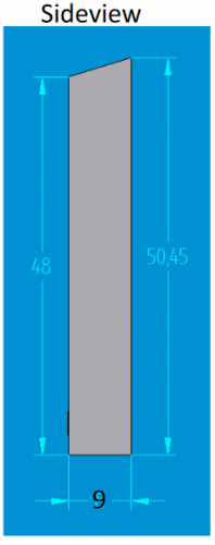
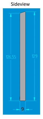
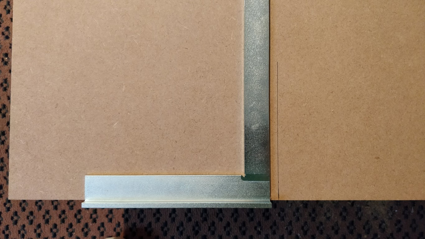
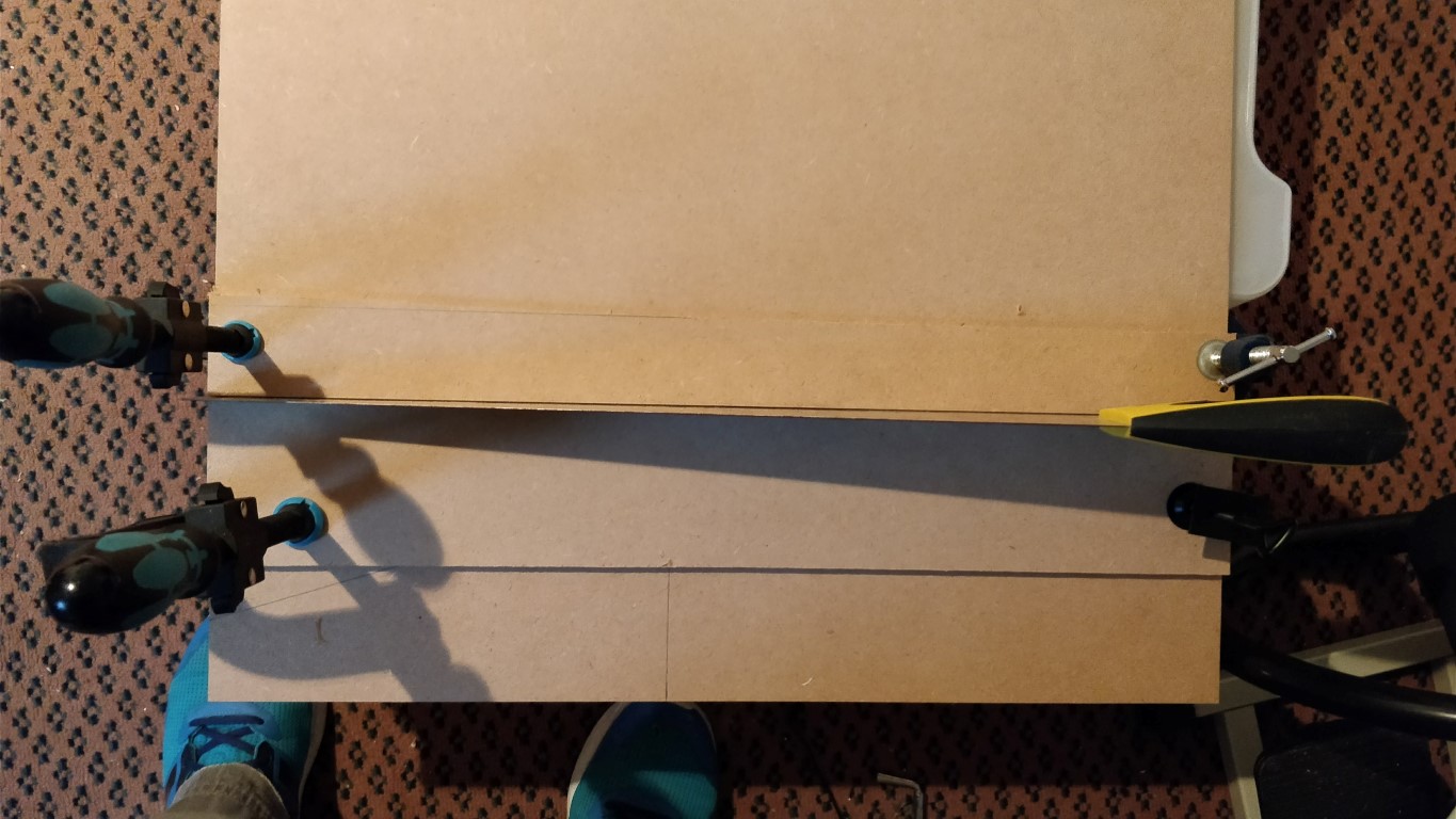
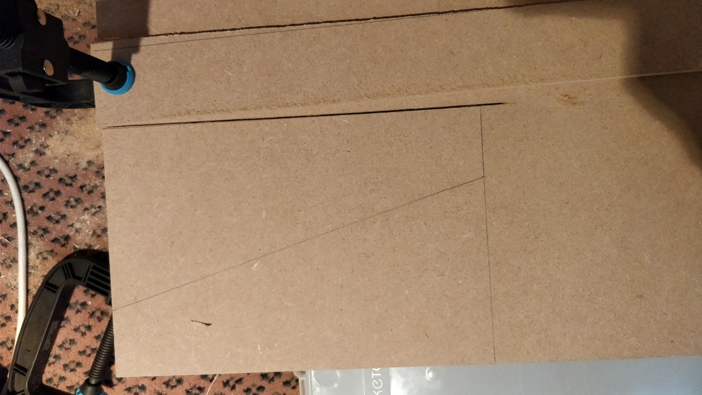
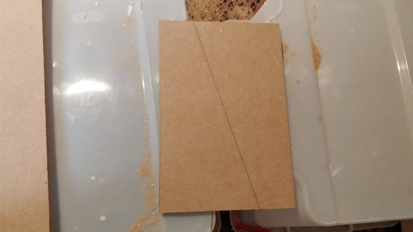
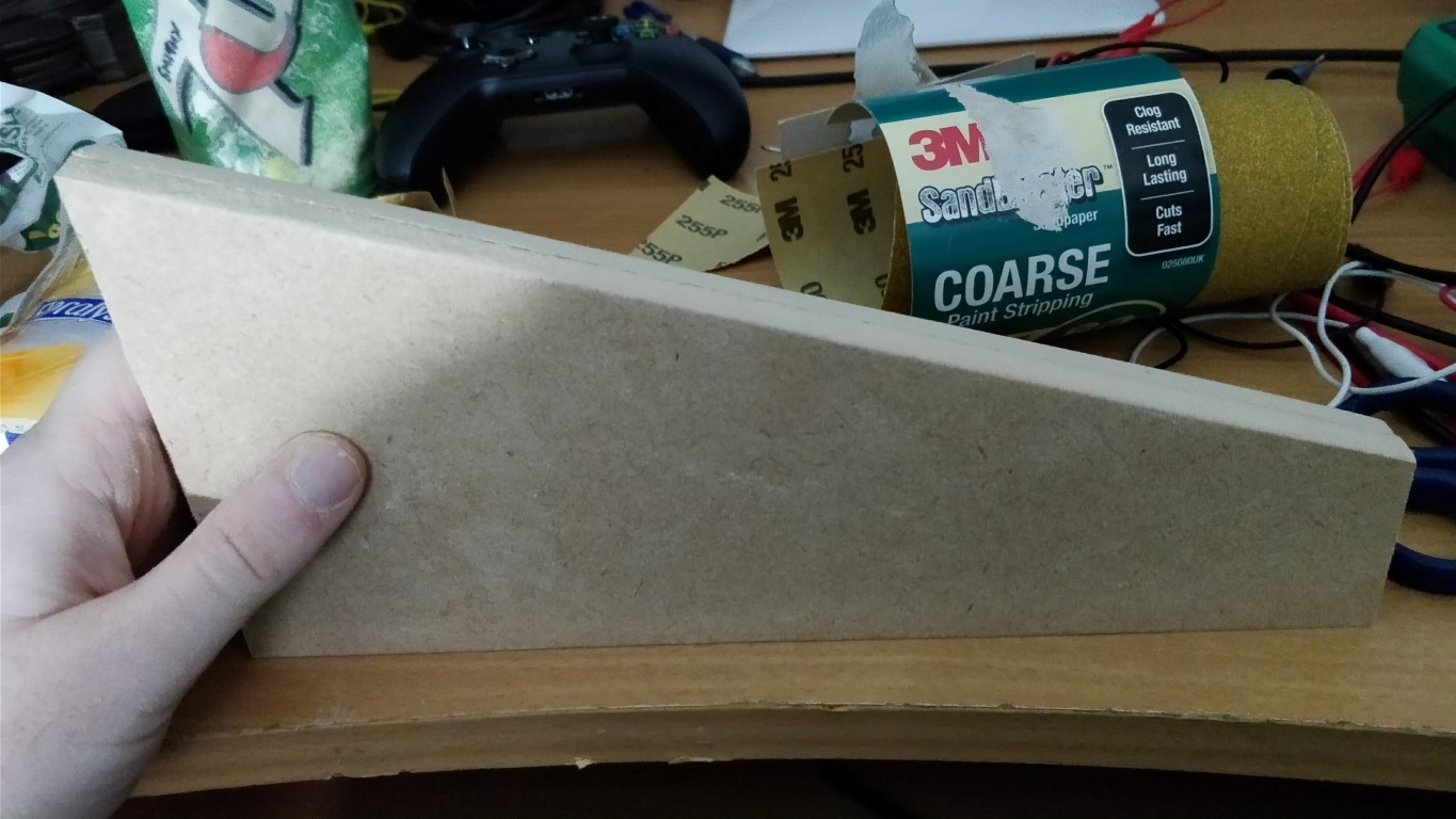
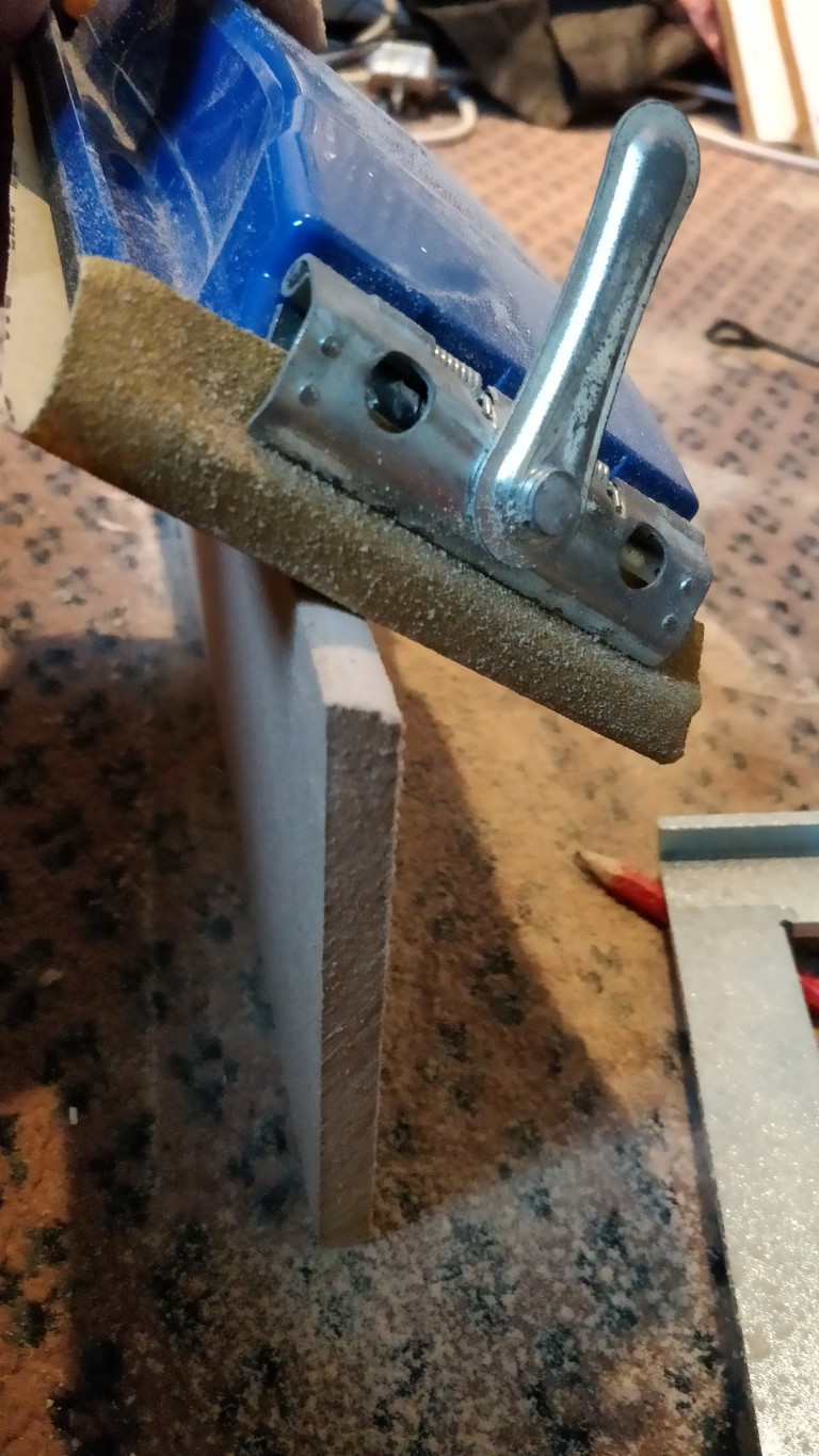
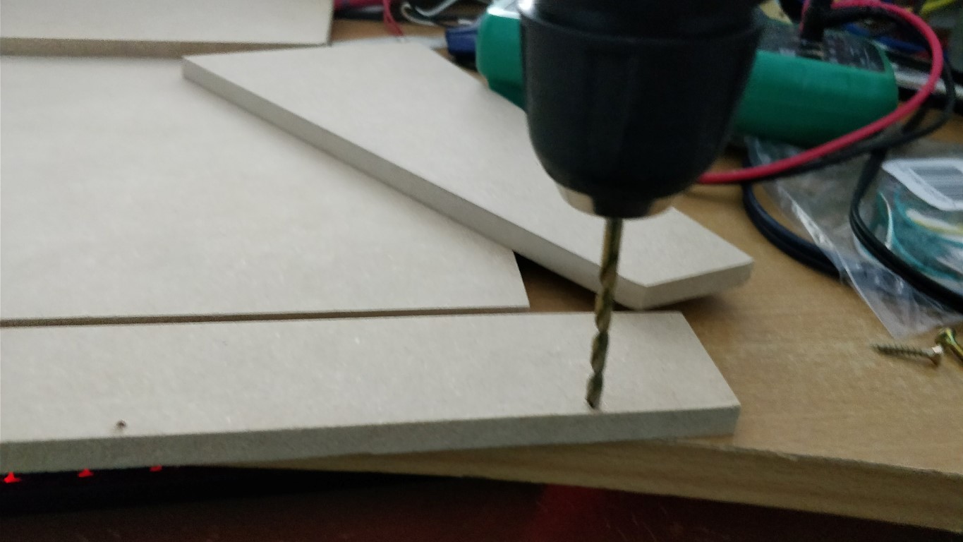
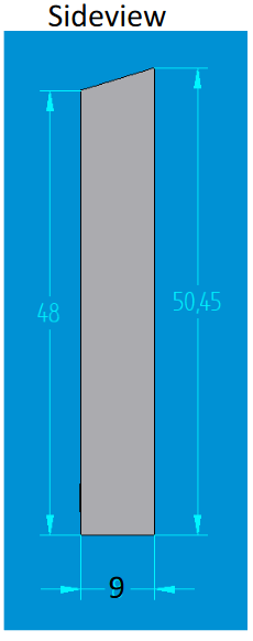
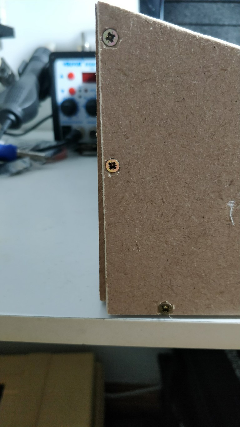
Bonus Step A: Building the Wooden Case First of all I would like to say a big thanks to Technobreath for designing a wooden case for MIDIbox Quad Genesis. This case is designed to be easily reproduced by the community without much skills or tools needed. You can download Technobreath's build instructions here which has all the dimensions you need to cut out each side of the case: building-instructions4-ilovepdf-compressed.pdf If you have better skills or tools at hand, feel free to build the case your own way and please share how you done so in this thread. Materials needed: Sheet of 9mm thickness MDF (Medium Density Fibrewood), Plywood or Birch. I used MDF as it was easy to obtain at my local diy store. 26 pcs of 3.5mm x 20mm Wood or Drywalll Screws. Metal threaded inserts for wood, suitable for 3M internal screws, for mounting the Allumimium Front Panel and PCBs to the wooden case. Alternatively you could use motherboard style standoffs and epoxy. 2 narrow lengths of Wood to be used as a simple jig to help you cut in straight line. e.g. Width = 5mm Length= 365mm minimum (the maximum length of our wooden panels). These will be held in place by C Clamps. It is extremely important that each length of wood has a perfectly straight edge on one of the long sides as it will guide you when cutting. Please watch Leah's awesome youtube video where I discovered the idea of using a simple jig here: Recommended Tools: A workbench, or something to keep the wood on top of while sawing. I just used 2 plastic boxes / crates to keep the wood elevated on the floor of my studio. Handsaw suitable for cutting your wood type Measuring tape + Pencil / Pen / Marker Ruler: for drawing diagonal lines Carpenters Square for drawing perpendicular lines to the sides of the wood. 4 big C-Clamps for holding the jig in place. Cordless Drill PH2 Philips Bit for the screws Drill bits suitable for Wood. a 2.5mm bit for pilot holes and a 4.0mm bit for clearance holes is recommended. Countersink bit for allowing the heads of the screws to go beneath the surface of the wood Sandpaper. 80 Grit recommended for adjusting non-smooth cuts, and 120 grit recommended for finishing. I also have a handheld sandpaper holder which makes it much easier to hold while sanding. Step 1: Creating the Side Panels Draw out the wedge shaped side panels of the case, I drew both of mine inside a rectangle so I could cut both in one go saving wood. Drawing the perpendicular line: I used my measuring tape and the measurements in Technobreath's PDF to mark both ends of the diagonal line before drawing a line between those markings with a ruler: Setting up the Jig with 2 pieces of wood and C Clamps parallel to the line I'm cutting, spaced the width of the saw apart: First side cut: Second side cut: Setting up the Jig for the diagonal line: Here is the picture of both side panels cut out. Notice how one of mine is taller than the other while placed on a flat level surface, my desk in this case. This is nothing a bit of sanding can fix. You can use C Clamps to hold the panels together while sanding so you can see visually when the height of both panels match. Ensure you line up the other sides correctly. Step 2: Creating the Rear Side of the Case For the back panel simply measure the dimensions in the PDF and draw the rectangular shape on the sheet of wood. Use the same method of using the jig in Step 1 and cut out this rectangular shape. The top side of this panel will need to be sloped to allow our Aluminium front panel to lie on it flat on it. At the side of the panel measure and mark the lower height with a pencil i.e. the height of the panels front side: Now sand the top of the panel at an angle until you get the slope required. I found it easier to sand than to cut with a saw as theres no real way of holding a jig in place with my tools. Here's the finished result: # Now hold the back panel upto the side panels and inspect if the slope is smooth between both panels. As you can see from the picture mine is not perfectly smooth so the top of the back panel is going to take a little sanding until it is flush with the side panels. Step 3: Create the Front side Simply measure, mark and cut out the rectangle for the front side of the case as per the PDF. The top side of this panel is sloped also to match the side panels, so we will need to mark the shorter length on the side of the panel and sand it down to this marking just like we did with the rear panel: Now stand the front side next to the side panels and inspect if further is sanding is necessary: Step 4: Creating the Bottom Side of the Case Measure, mark, and draw out the rectangle for the bottom panel of the case using the dimensions in the PDF. Cut it out using the jig method as usual. Now we should have something that resembles a full case: (it is just freestanding in this photo) Step 5: Screwing the Case together I decided to screw the front side to the bottom side of the case first. First I marked the hole of where the right most screw will enter with a pencil. Since the thickness of wood is 9mm, I marked it about 4.5mm from the edge which is exactly half the length of the side of the bottom panel. Now we will drill the pilot hole through the front panel and bottom panel. Use a drill bit that is less than 3.5mm in diameter (i.e. the size of the screw) I used a pilot hole of 2.0mm suggested online, but I found this was too tight and lead to stress cracks in some of the wood. I would suggest using a bit with a diameter of 2.5mm instead. Ensure the side of the front panel is lined up perfectly to the side of the bottom panel before continuing! Ensure your drill is set to drill mode and not hammer or screw mode! Drill a hole in 20mm deep (10mm through the front panel and 10mm through the bottom panel.) Ensure your you are holding the drill perfectly straight so the drill bit doesn't go in at an angle. Next we will drill a clearance hole in the front panel only! The clearance hole must be slightly bigger than the diameter of the screw e.g. 4.0mm. Simply drill the clearance hole through the existing pilot hole in the front panel to make the hole wider: Next using the countersink bit, drill a cone shaped hole into the clearance hole at the front of the front panel just deep enough so the head of the screw will go under the panels surface and will not be sticking out. Next we will change the setting on the drill to Screw, you can apply a torque setting of about 5. And we will screw our first screw through the clearance hole in the front panel and pilot hole in the bottom panel screwing the case together! The result should look like this: (Notice this picture was taken of the left most screw on the panel!) Now repeat the process for the 3 other screws on the front panel! Step 6: Screw the back panel to the bottom panel using 4 screws Screw 4 screws through the back panel and bottom panel using the same method. View from back of case: View from front of case: Step 7: Screw the side panels to the bottom panel using 9 screws per side Use the same method for this step also. Now we should be left with a case looking something like this: Now ensure the length and width of the case matches the Alluminium Front Panel. The length of the case should be as close as possible to 381mm, and the depth of the sloped top of the case should be as close to 279.4mm as possible. If you are off by a few millimeters you could always customize the Front Panel file for the Alluminium Front Panel, and change the co-ordinates for the screw holes before ordering. My case was not 100% perfect, due to either human error when cutting out the bottom panel or because one side of the sheet of MDF was not cut perfectly straight in the factory. The depth of the bottom panel ended up being longer than it should. As you can see the back panel of the case overlaps the side panels: I was a bit gutted but decided to keep it and move on with the project as the dimensions at the top of the case seems to match the dimensions of the Alluminium Front Panel closely enough. Don't be put off by this post! I had zero skills in woodwork when starting this project and I still managed to make a usable case with hand tools, there's no reason you can't either! Hopefully you will have better luck!
.thumb.jpg.cc28c09e7ade18304ca8e815ea34b16e.jpg)


-
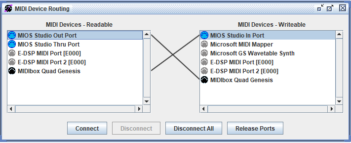
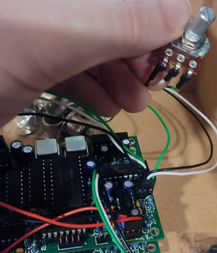
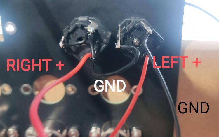
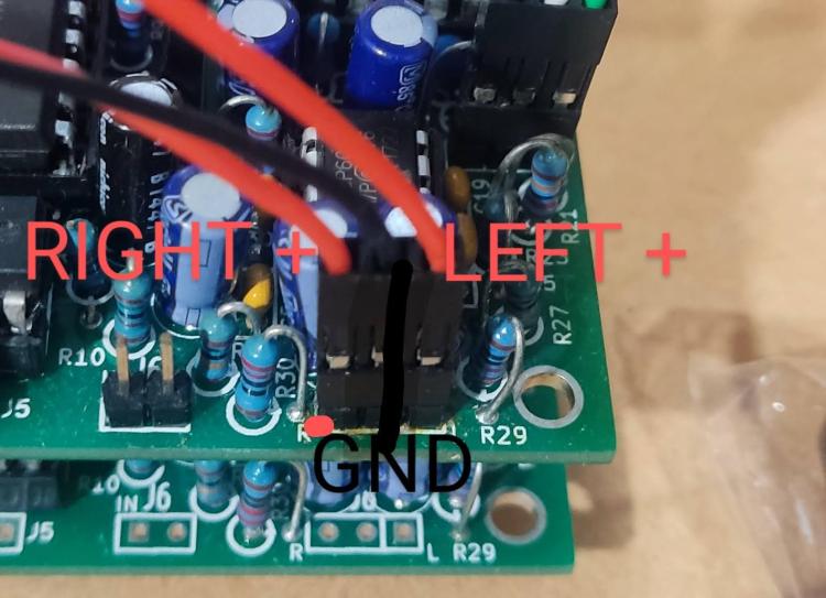
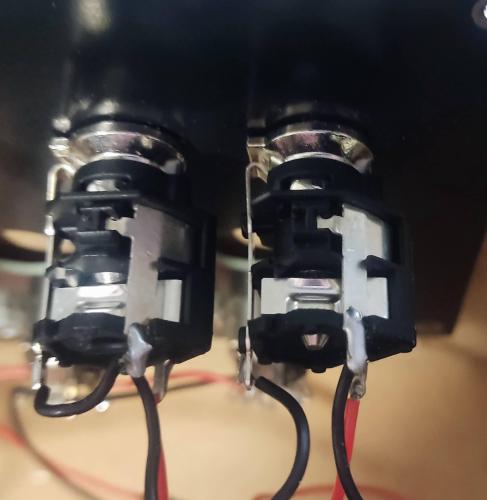
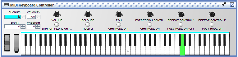
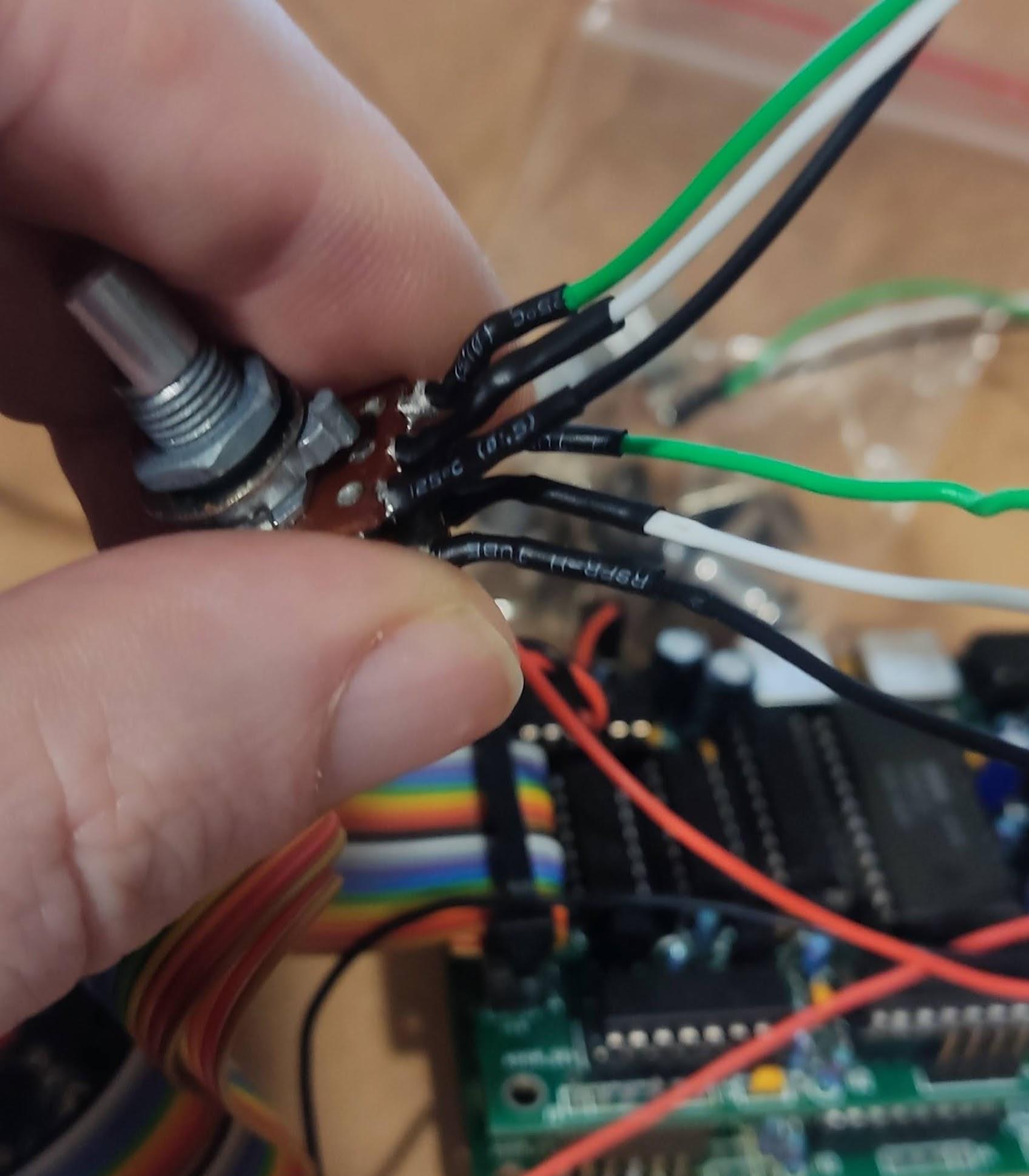
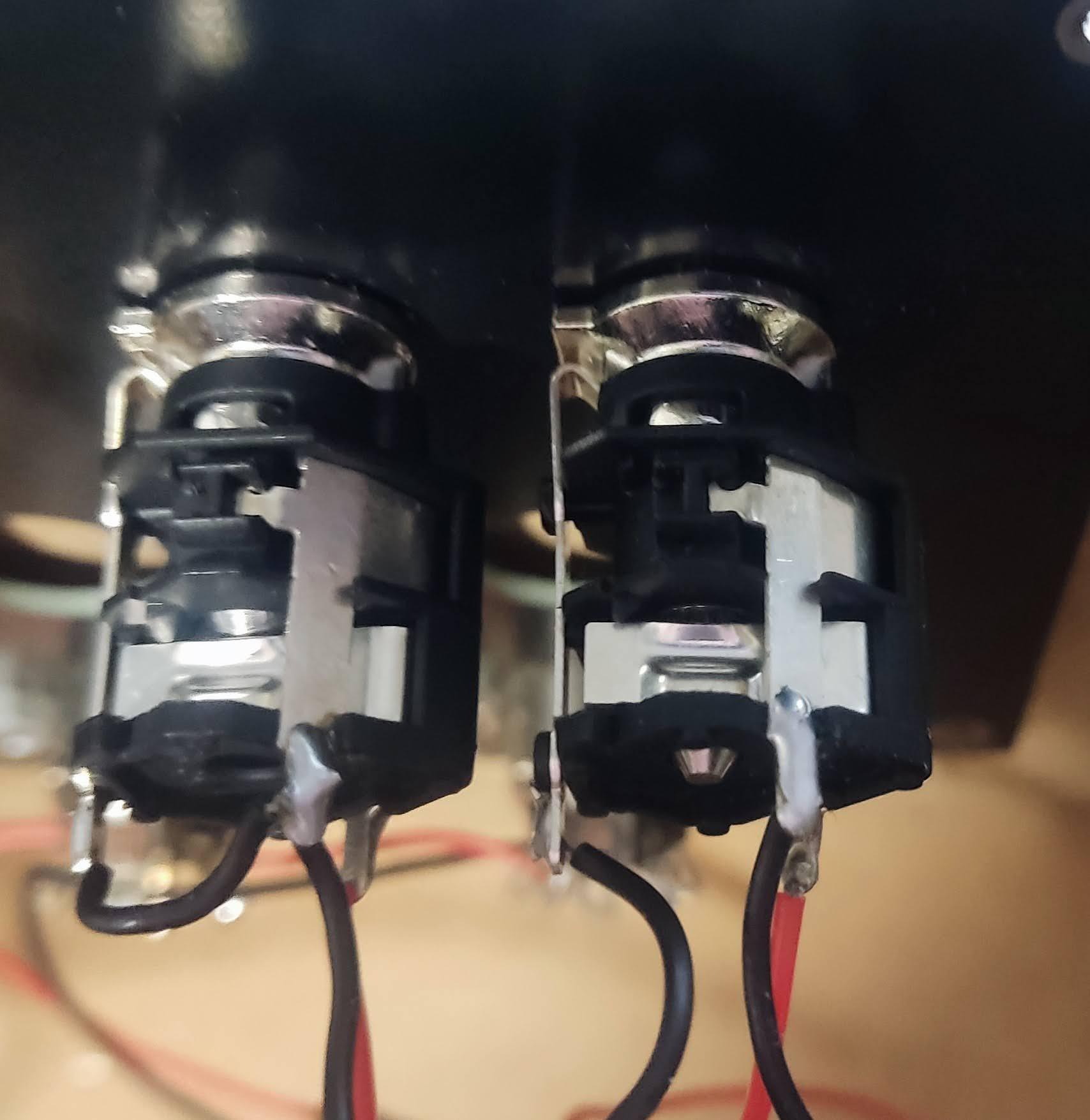
Step 12: Testing the sound To test the sound we need to either connect the potentiometers to R18, R19, and R20 headers of the Genesis Module, or we can connect jumper wires to the Input and Output pins of each header to test it more quickly. If you want to connect the potentiometers and L/R audio sockets scroll down further. Jumper the following points on R18,R19 and R20: As you can see the Square pads are GND, the next is Input and the 3rd Pad is Output. Crimp a 3 pin audio cable for the Stereo Output header J8, and solder the audio jacks according to the folliwing pinout: Pin Label Function 1 – Left channel output 2 GND Ground 3 – Right channel output In the picture below I just used a crocodile clip attached to the Tip of a 3.5mm audio cable as I'm waiting on a delivery of audio jacks. OR Solder the potentiometers and audio sockets. First we will solder and crimp the wires for the YM2612 output. Crimp R19 wires to fit a 3 pin Dupont connector that goes into the R19 pins of the Genesis Module. Then solder the other end of the wires the bottom terminals of the dual gang pot. Black =GND White = Input Green = Output Crimp R18 wires to fit a 3 pin Dupont Connector that goes to the R18 pins of the Genesis Module. Then solder the other end of the wires to the top terminals of the dual gang pot. Next we will cirmp solder the wires for the PSG which uses the Single Gang Potentiometer. Crimp 3 wires for the 3 pin Dupont Connector which goes to the R20 pins on the Genesis Module. From Left to Right: Black = GND White = Input Green = Output Now we will crimp and solder 3 wires to the 1/4" audio sockets. Crimp 3 wires and use a 3 pin dupont connector as shown.. Ensure the 1/4" audio jacks are mounted so that the correctly so that the metal contacts are on top as shown in this picture: Solder the LEFT+ (positive) wire to the bottom right of the terminal of the L/Mono audio socket as shown. Solder the GND wire tom the top right terminal of the Left/ Mono audio socket as shown. Solder the RIGHT+ (positive) wire to the bottom right terminal of the Right audio socket as shown. Then solder a short GND wire from the leftmost terminal of the L/Mono socketr to the Top right terminal of the Right socket. I also soldered another short GND wire from the Top Right terminal of the Right Audio Socket to the leftmost terminal of the Right Socket. Plug in your 1/4" cables to the Left and Right audio sockets to test the audio in the next step. Next ensure the Java runtime is installed on your computer, if it isn't then install the latest runtime from www.java.com Download and extract MIOS Studio 1 from this link, but do not run yet! http://www.midibox.org/miosstudio/MIOSStudio_beta9_4.zip (We are using the older version of MIOS because it allows us to right click the keyboard and hold notes to test polyphony easier using just a mouse.) Power on your MIDIbox Quad Genesis and connect it to your PC/Mac via the Micro USB Cable. Wait for the LCD Screen to show the status screen and now run the MIOS Studio 1 .jar file. Click Options -> MIDI Device Routing and Connect MIOS Studio Out to MIDIbox Quad Genesis on the right hand side, and connect MIOS Studio In Port to MIDIbox QUad Genesis on the Left hand side, as shown in this picture: Close the window, and change the MIDI Channel to Channel 2 on the Virtual MIDI Keyboard Controller: Now play a note and you should hear a piano patch play on the FM Chip! To test the polyphony right click on 4 notes and each note play. Clear the 4 notes by left clicking on them (If you right click on more than 4 notes, youll notice some notes will no longer play - this is because in its current state MIDIbox quad genesis is expecting 4 FM chips which are not there, and is trying to allocate notes to the 2nd, 3rd and 4th chip!) Now set the MIDI channel to channel 3 and play a note to test the PSG Chip. Right click on 4 notes and ensure they play. If everything is setup properly you should have sound!
.thumb.jpg.5f46516a296618d5936bb4b6d38a4f49.jpg)

.thumb.jpg.d18864699678b6e4163d5aa555327f2a.jpg)

-
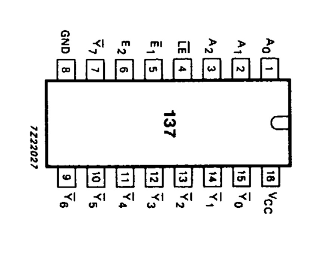
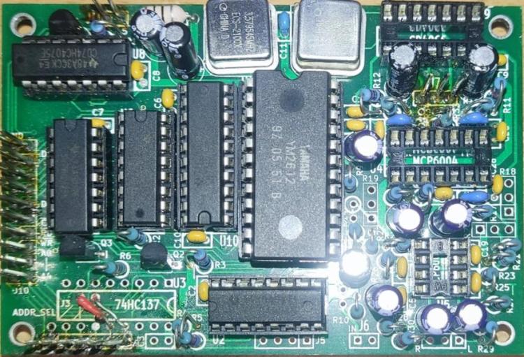
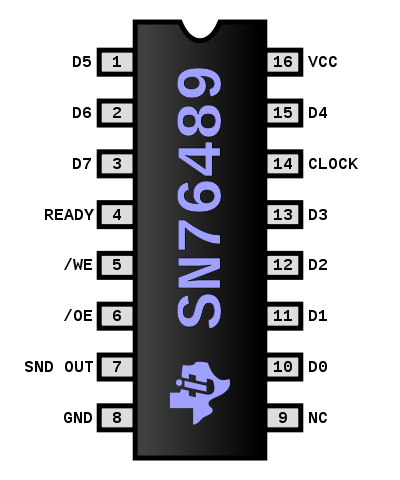
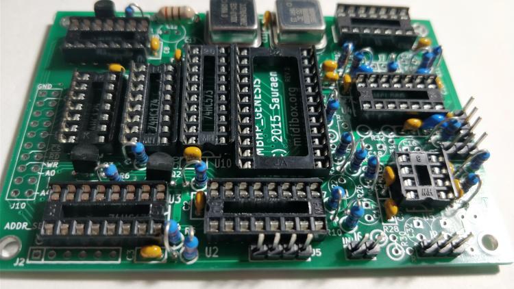
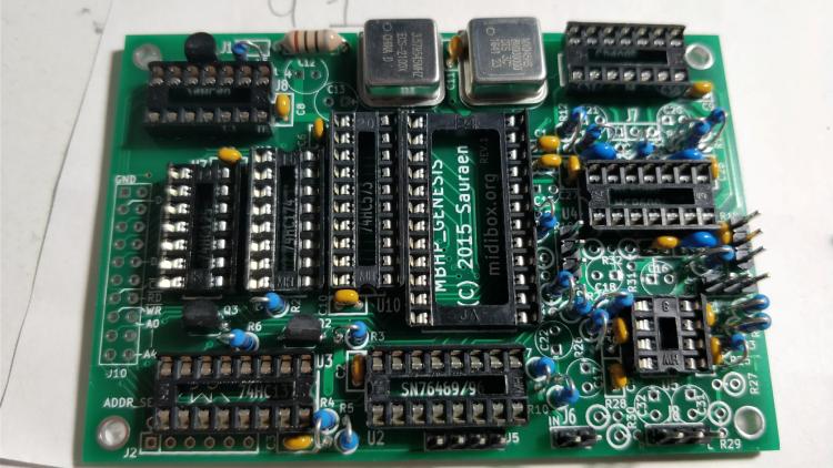
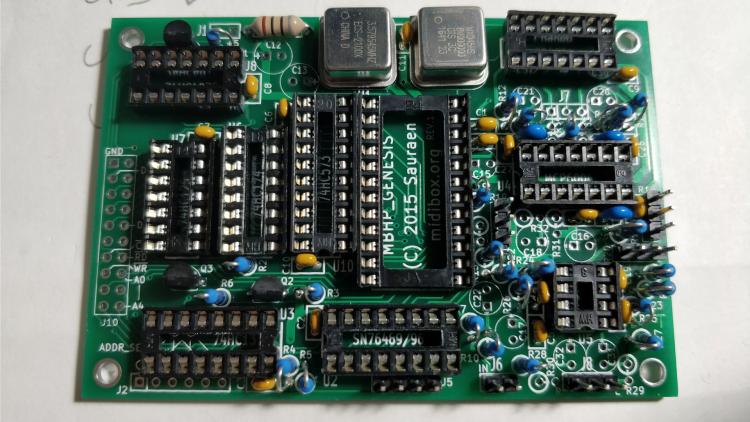
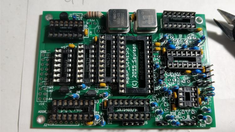
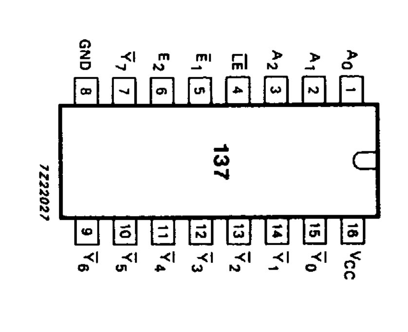
Step 11: Populating the ICs in the Genesis Module **Please ensure MIDIbox Quad Genesis is powered off!** **Please ensure the correct orientation when installing the IC's, ensuire the semi circle of the chip lines up with the semi circle of the socket!** When installing IC's, you should gently straighten the row of legs on one side by pressing the row gently against your work bench. And repeat for the row of legs on the opposite side. The legs are usually to far apart to push into an IC socket. Install the YM2612 or YM3438 in socket U1: Install SN76489 or SN76494 or SN76496 in socket U2: Install the 74HC137 in socket U3 Install the MCP6004 in socket U4: Install the MCP6002 in socket U5: Install 74HC174 in socket U6. Install 74HC125 in U7. Install 74HC4075 in U8: Install CD4066 in socket U9 And finally install 74HC573 in U10. Done!
.thumb.jpg.859d528cd6e85425ea39ed7b52dabf20.jpg)
.thumb.jpg.a3f6f98795b6ef3a3546201eaa28aa1a.jpg)
.thumb.jpg.f85dfb1b90de0f52a37867d04310bd53.jpg)
.thumb.jpg.63597e36f943869d9653a5c7565a3b57.jpg)
.thumb.jpg.ad20f2b61b59cc4e20aa2ad7513a3def.jpg)
.thumb.jpg.1e302f1bdd06a53ea92e2085e3112022.jpg)
.thumb.jpg.bd1331a9a9ff4e010c8f2aeaf4ccc69a.jpg)
.thumb.jpg.949f778dc3d048fac25a40d0da386a66.jpg)
-
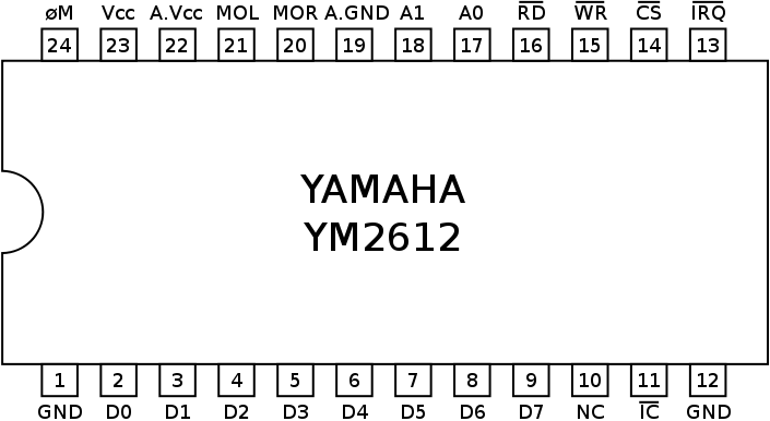
Step 10: Testing the voltage of the Sound chips sockets: First we will test the voltage going to socket U1 of the YM2612 or YM3438. With MIDIbox Quad Genesis powered on connect the black probe of your multimeter to PIN 1 - GND of the socket and connect the Red Probe to Pin 23 - Vcc (5V DC). You should be getting a reading close to 5.0V. Next lets test the voltage going to our PSG Chip, socket U2. Place the Black probe in PIn 8 of the socket which is GND, and the red probe in Pin 16 of the socket which is Vcc or +5V You should be getting a reading close to 5V.
-
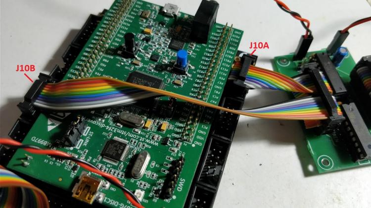
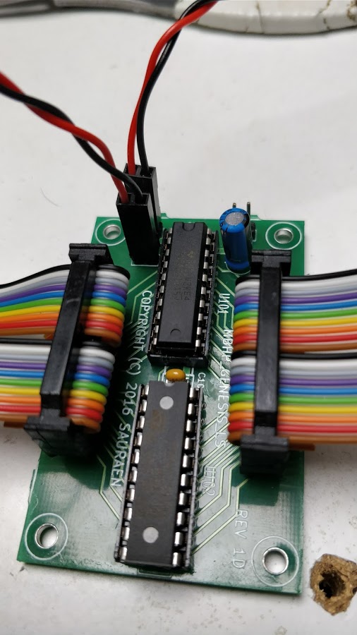
Step 9: Wiring the Core, LS Shifter and Genesis Module. **Ensure the power is switched off before proceeding!** First up the easy bit, wiring the Genesis Module to the LS Shifter. This is done by using 2x 10 pin ribbon cables and a 2 x 20 Pin DIL connectors. Please consult Smash TV's guide for crimping the DIL connectors. The cables will be going from J102 of the LS Shifter Module to J10 of Genesis Module. Notice how both cables are straight without any twists to the cable, to match the pinout of the LS Shifter and Genesis module. As usual we have bent the cable in a U shape around the connectors, just like we did with the connector of the LCD module that plugs into the core: Note: I left the cable a bit longer than I should have! Now lets do the trickier cabling between the LS Shifter and the Core Module. We will be using 2x 10 pin ribbon cables with one 20 pin DIL connector for the pins of the LS Shifter module. And we will be using 2x 10 pin DIL Connectors for the 2 cables plugging into the core module. Measure the length of the top 10 pin ribbon cable between the J101 of the LS Shifter pins and J10A of the core. (Cut the length ensuring there is enough length for the cables to bend around the Connectors in a U shape) Measure the length of the bottom 10 pin cable between the J101 of the LS Shifter Module and J10B of the core. (Cut the length ensuring there is enough length for the cables to bend around the Connectors in a U shape) You can now crimp the 2x 10 pin cables inside the 20 pin DIL connector that connects to J101 of the LS Shifter Module. Before crimping the connectors for J10A and J10B of the core we must add 1 twist to each cable... so the pinout of J10A matches the upper half of J101, and the pinout of J10B matches the bottom half of J101. As you can see from the picture the orientation of the cable is inverted when going from J10A of the Core Module to J101 of the LS Shifter. i.e. the Brown wire is on top of the connector at J10A of the core but is on the bottom of the connector plugged into J101 of the LS Shifter Module. Go ahead and crimp the connector that plugs into J10A of the Core Module, ensuring it has 1 twisted as shown in the picture above. And ensure the cable is bent in a U shape around the connector itself like we did with the other connectors we crimped. Repeat the same process for J10B: Please refer to the pinout of J10A, J10B and the pinout of J101, and test for continuity between them to ensure you have the cables wired correctly. Next step is to crimp and connect 2x 2pin (Red and Black) Power Cables. The first will connect the 3rd Header of the power distribution board to J103 or J104 or J105 of the LS Shifter Module. All 3 are interconnected so it doesn't matter which one you choose. Please ensure the polarity is correct, Red / +5V on the left hand side and GND on the right hand side: The next power cable will connect J103 or J104 or J105 of the LS Shifter Module to J1 of the Genesis Module: Please note on the Genesis Module that +5 is marked on the right pin this time of J1! Ensure the +5V / Red Wire goes to the right hand side, and GND / Black goes to the left. Cabling Complete!
.thumb.jpg.4e5b2d55a09e6df87d033534082372d3.jpg)
.thumb.jpg.65b82ba57e4d7501b7f71ae3cea6692d.jpg)
.thumb.jpg.009b1d46da75adfb3e100b8f6f870e9b.jpg)


.thumb.jpg.9d947edc38bdc0084a32e5fb8745a38d.jpg)
-
This is a diy community, not Elektron or Roland. There simply isn't enough time or members on here to provide that level of documentation in videos. By all means, if you would like to go ahead and do such videos if you learn whats already available on ucapps, and the wiki go ahead. I'm sorry but if you can't follow the instructions that are already there then maybe this community isn't for you. Complaining that it isn't more user friendly is only dragging the community down and wasting peoples time. From a MIDIbox noob who can't code one line of C.
-
Seems fairly self explanatory to me and certainly not for "Experts". Whats so expert about turning a knob from left to right so the MIDIbox HUI receives it?
-
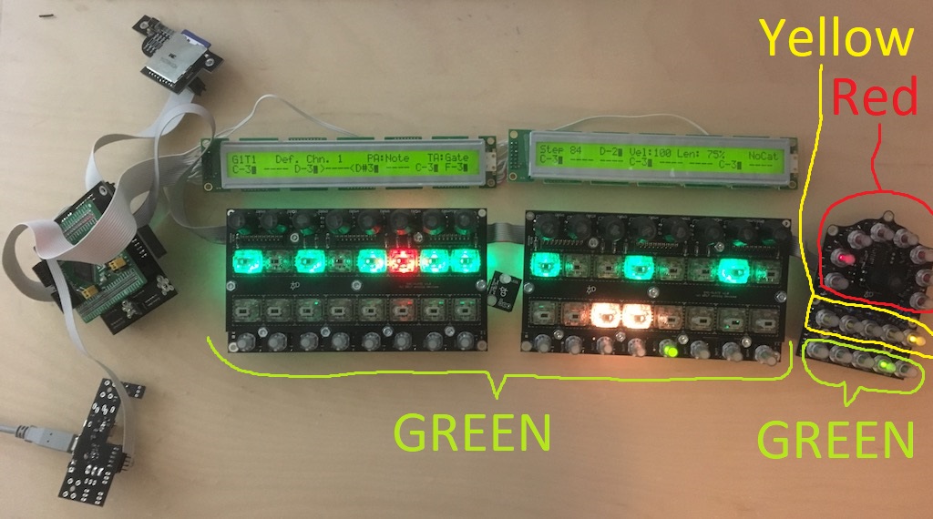
Is this the Colour Scheme you went with for the Standard LEDs TK?

-
Looks awesome tk and Andy well done! I'm still a bit unsure about the pages and controls in the demo as I don't own a seq. But it looks great! I'm particularly interested in what can be done in jam mode. I presume there's 16 dedicated track select buttons for recording meaning you press a button -> record a track, press another button and record that track?
-
For anyone else looking for one here's the cheapest I can find $6.80 delivered on Aliexpress via registered mail. https://www.aliexpress.com/item/STLINK-ST-ST-LINK-V2-CN-STM8-STM32-Emulator-download-programmer/32693170276.html Seems a better option than the little USB Stick ones with the dupoint cables. Who knows, may even come in handy for flashing modular stuff!
-
Thanks for the help. I think I'll play it safe and buy an ST-Link clone.
-
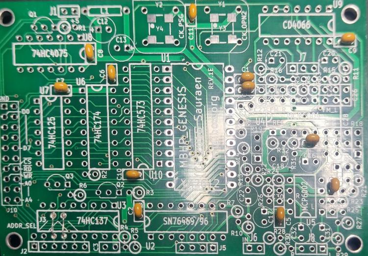
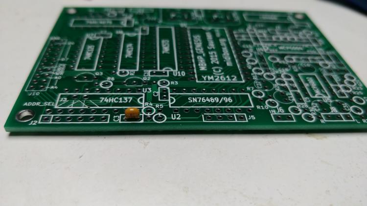
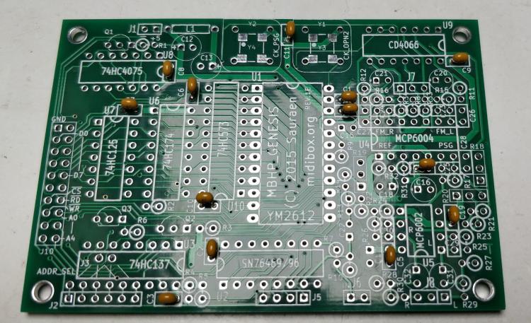
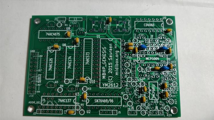
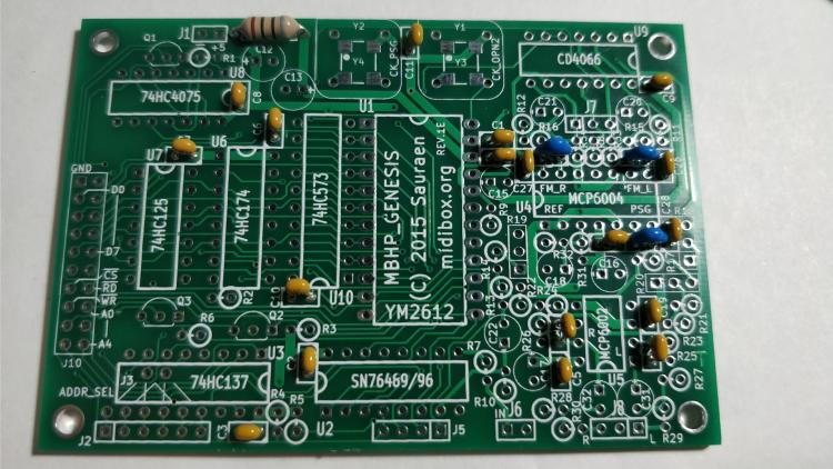
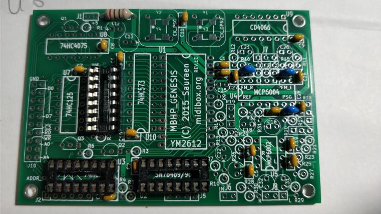
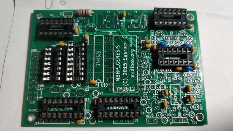
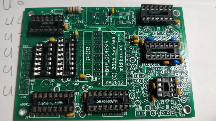
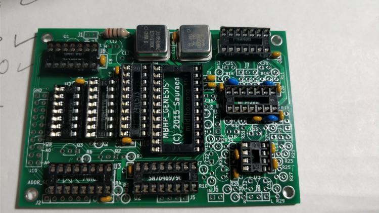
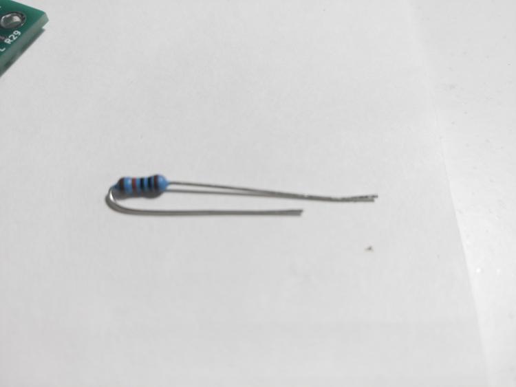
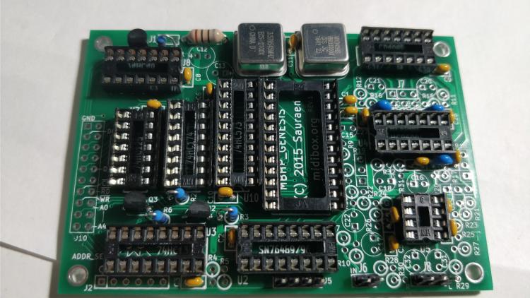
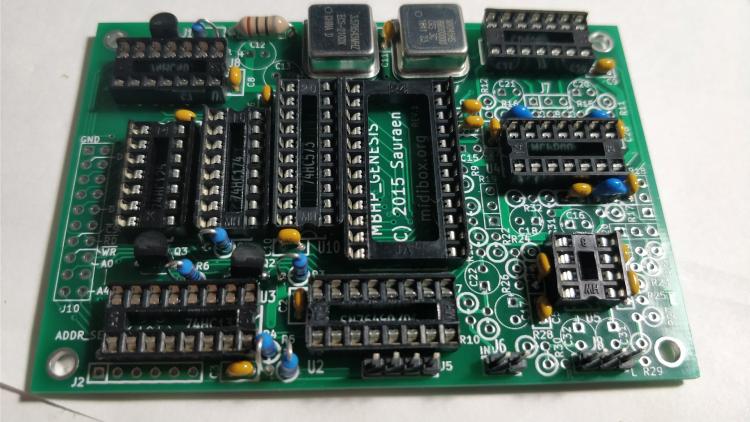
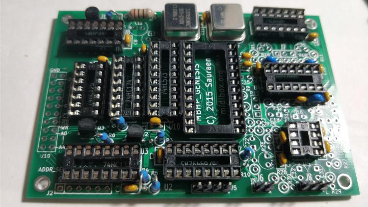
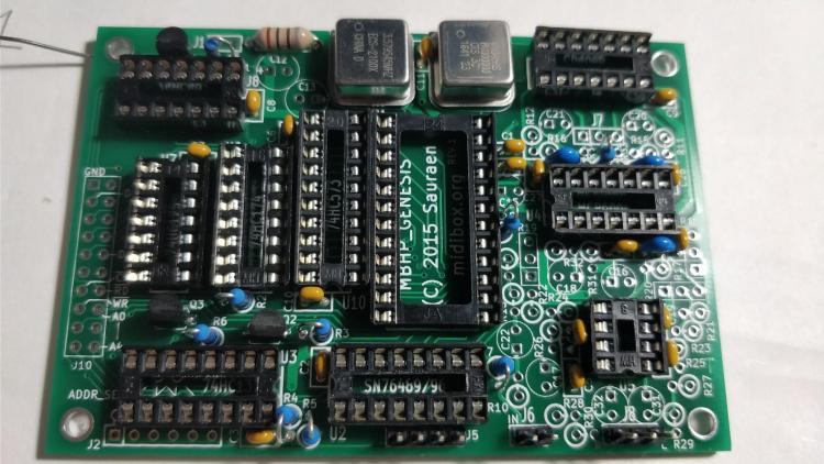
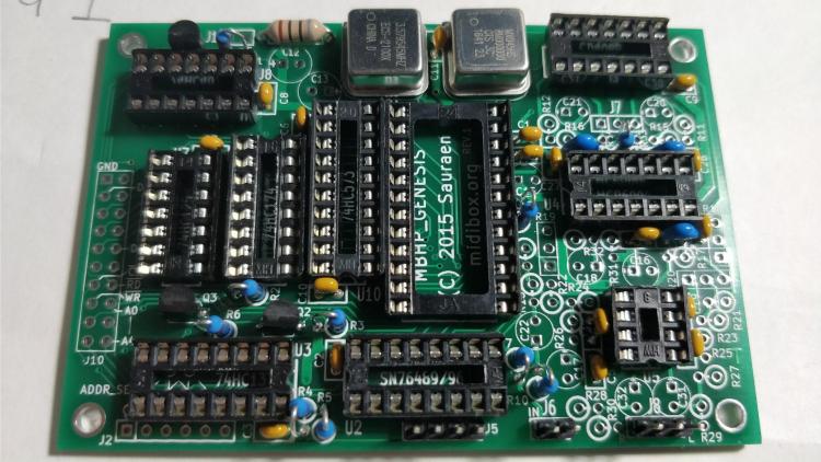
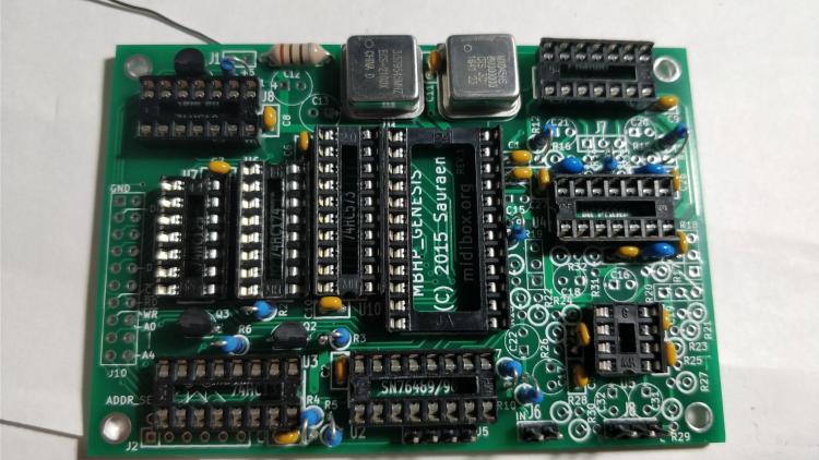
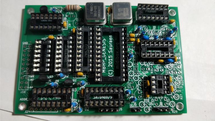
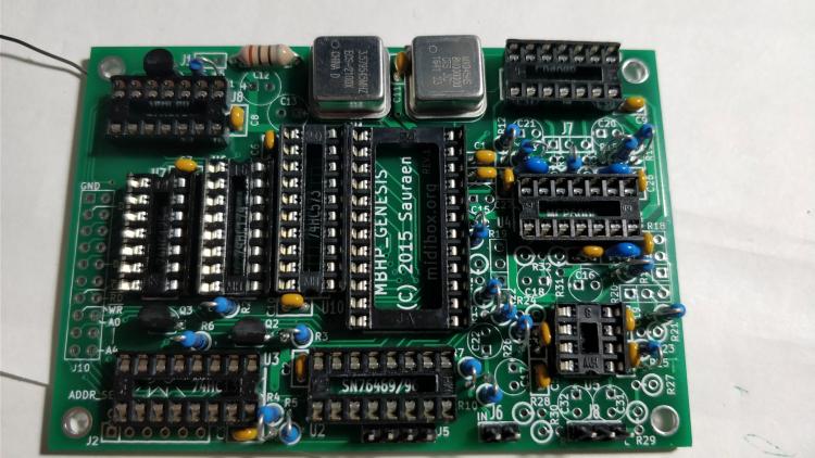
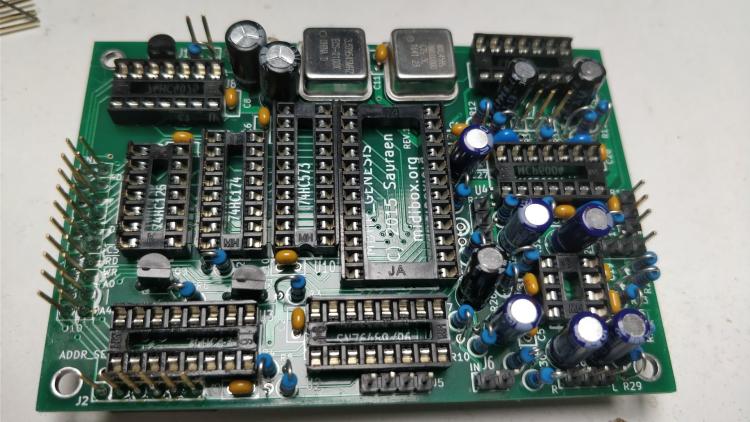
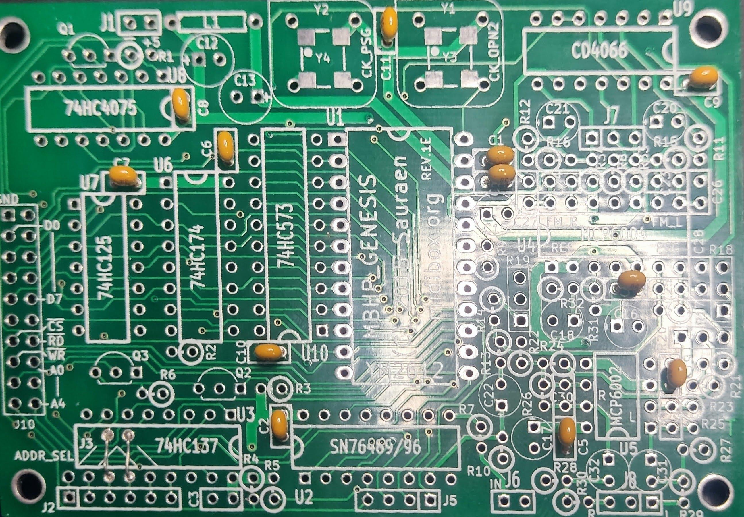
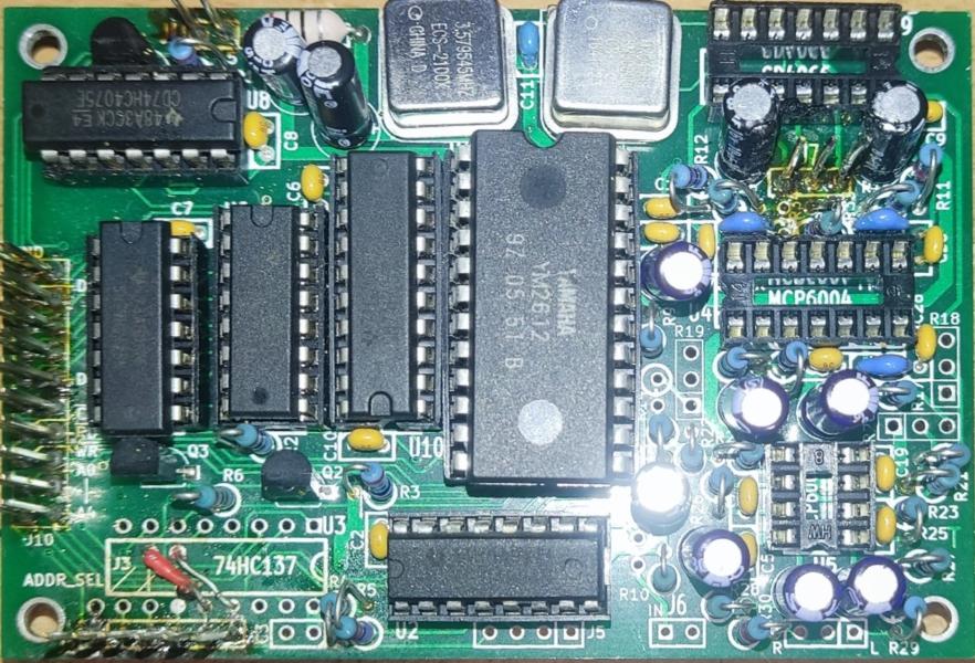
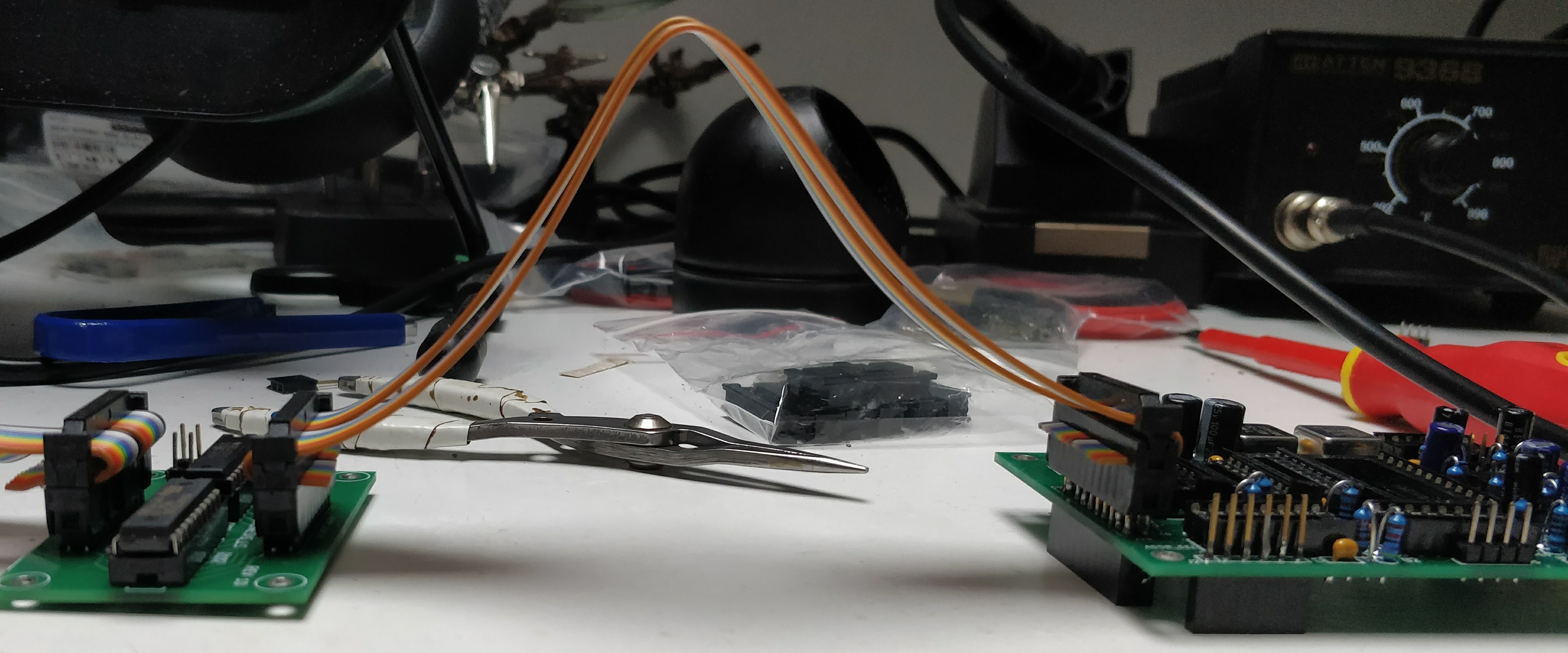
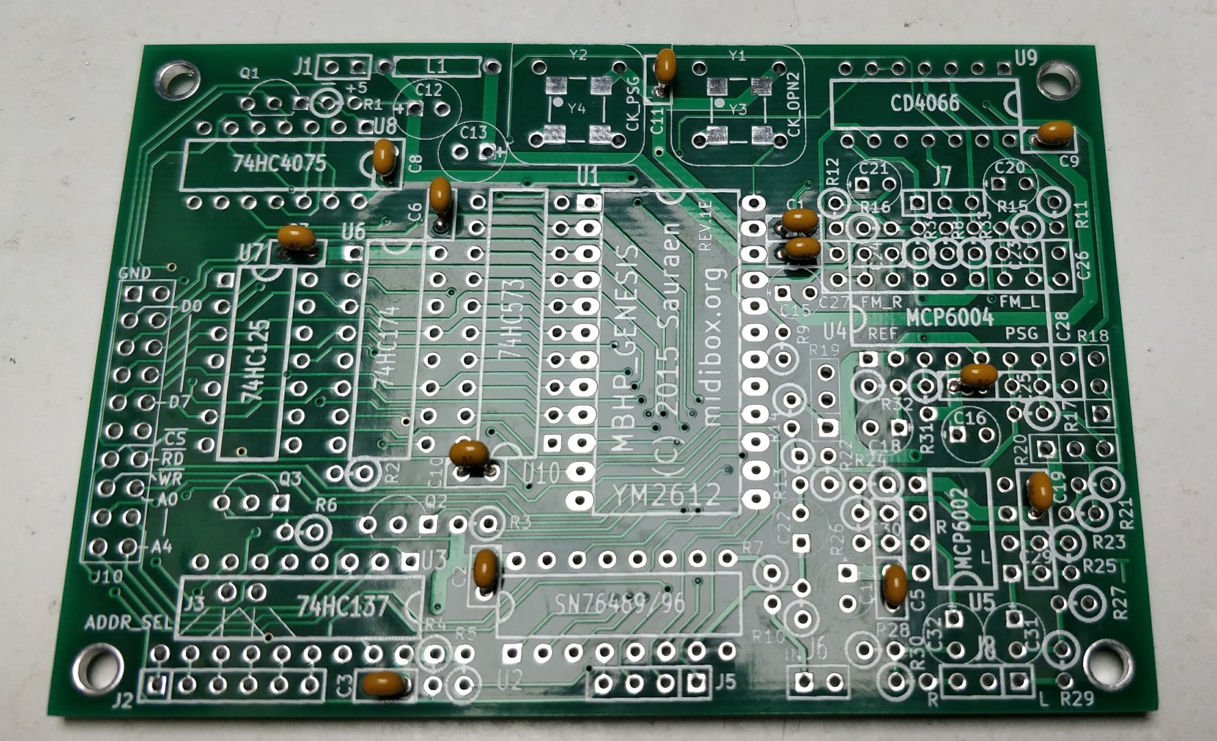
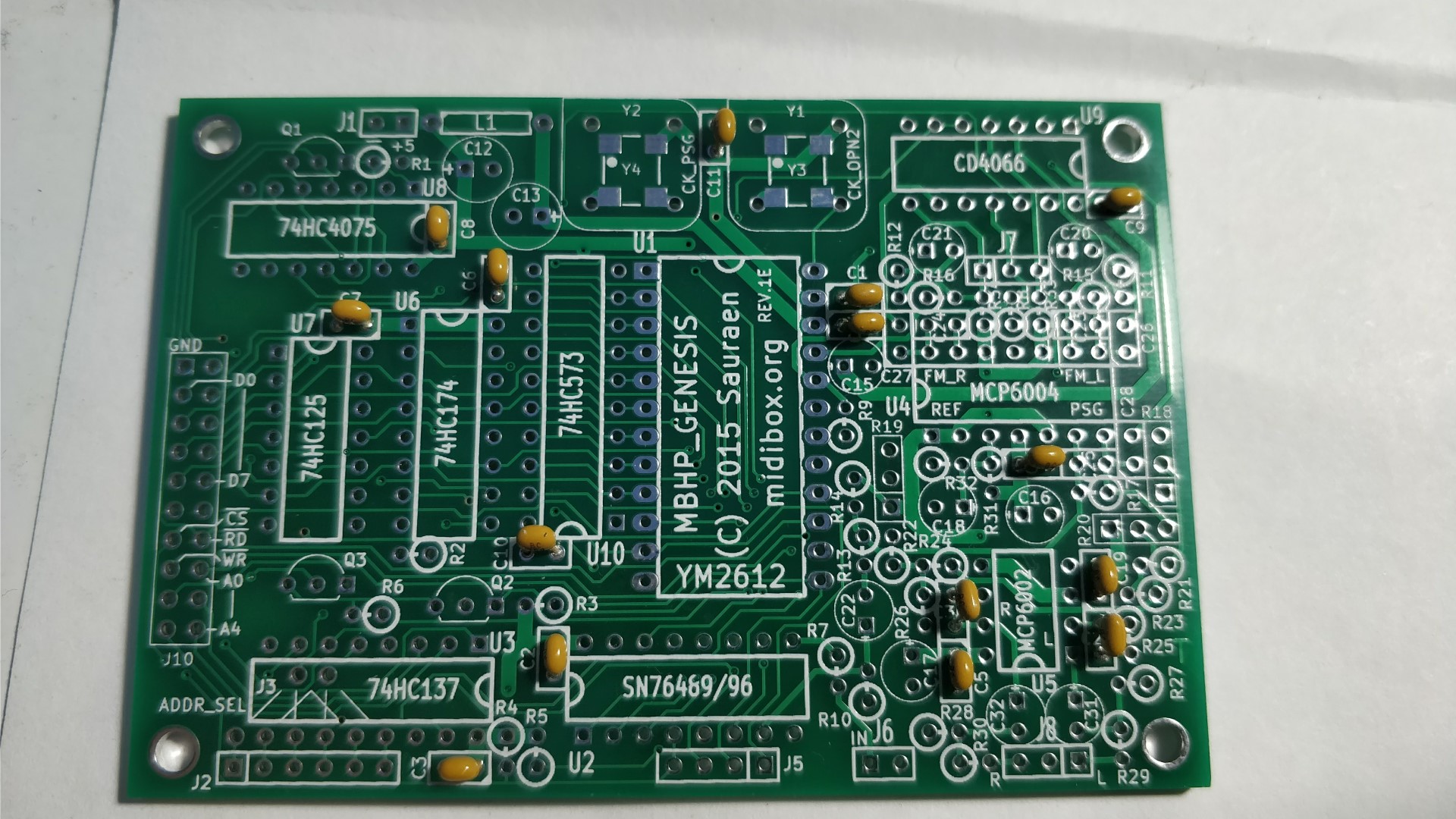
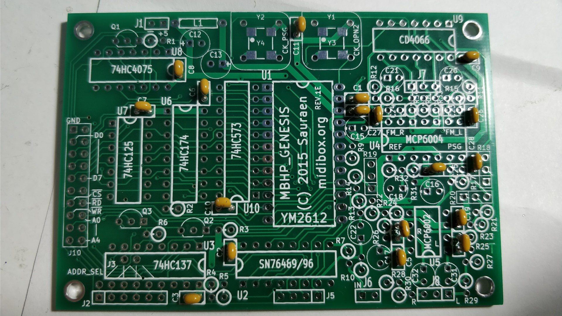
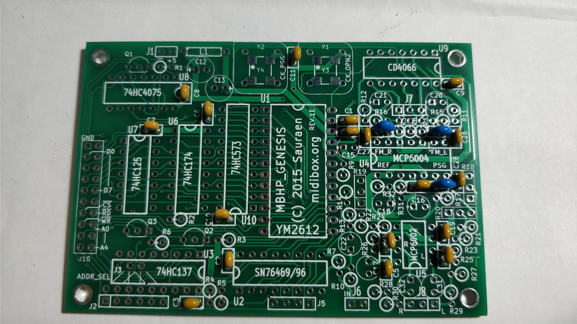
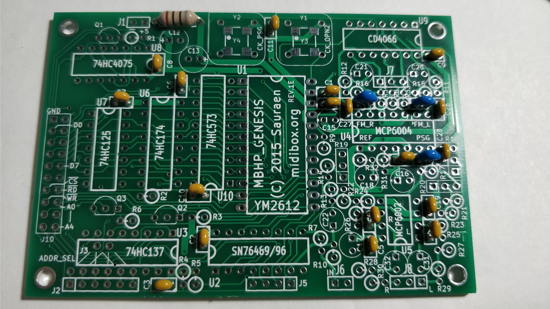
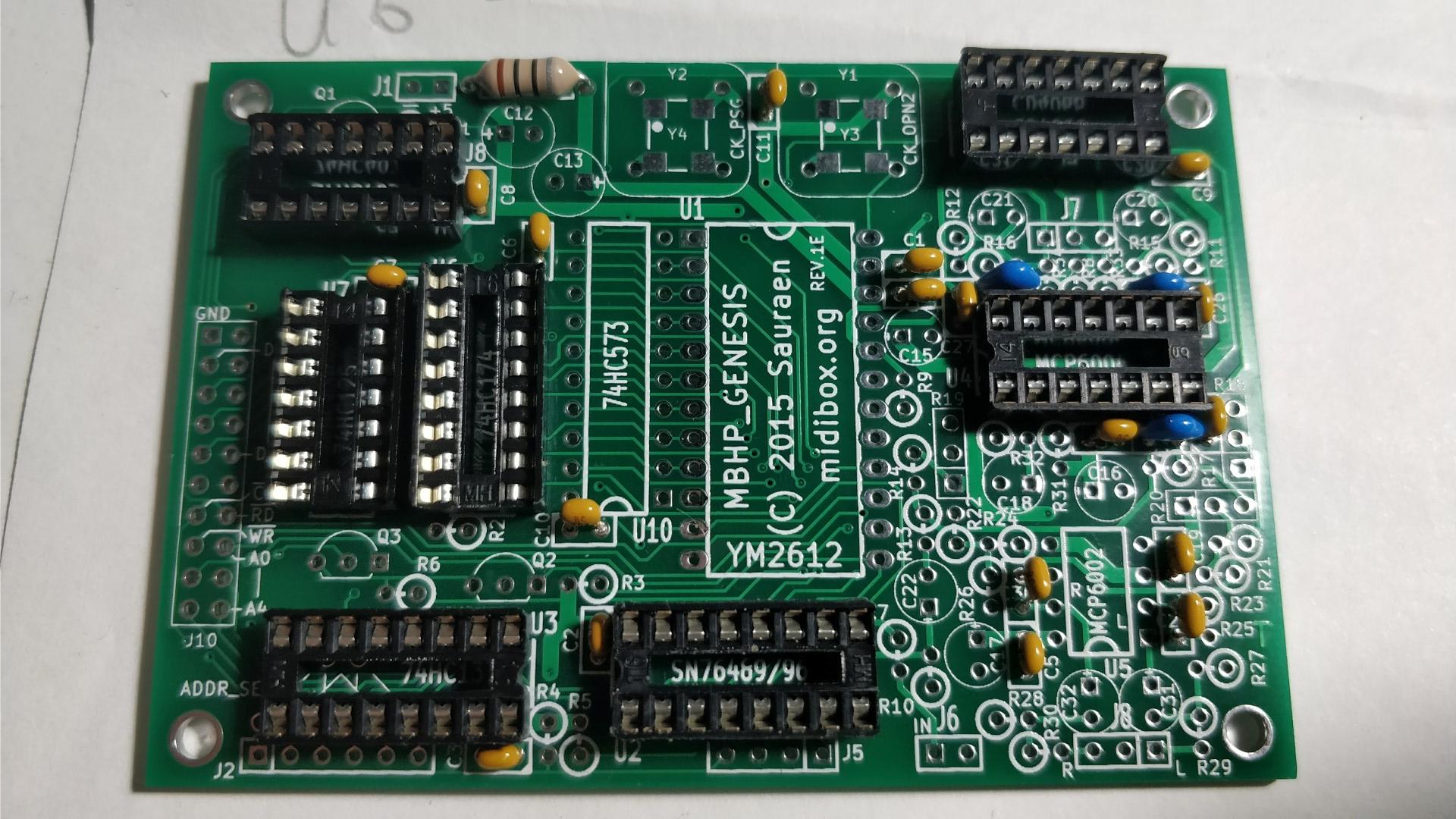
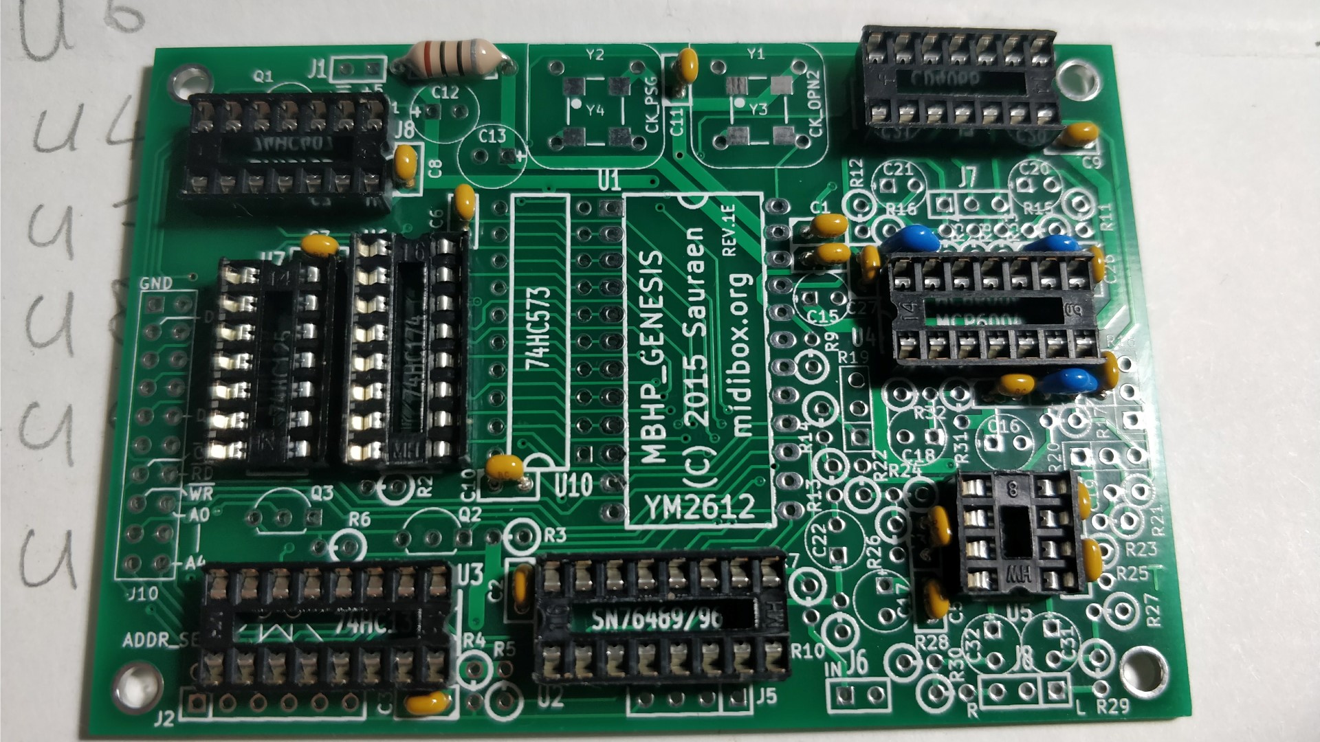
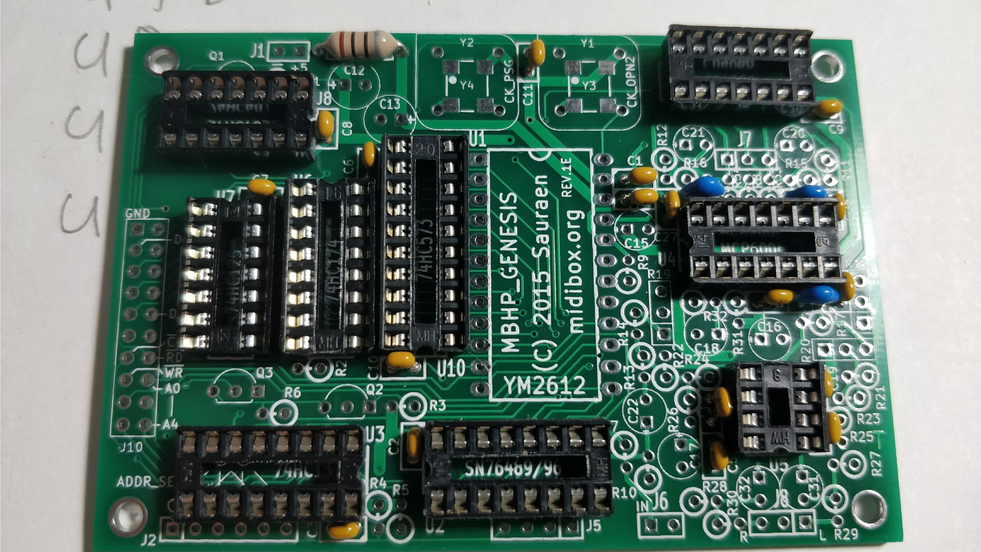
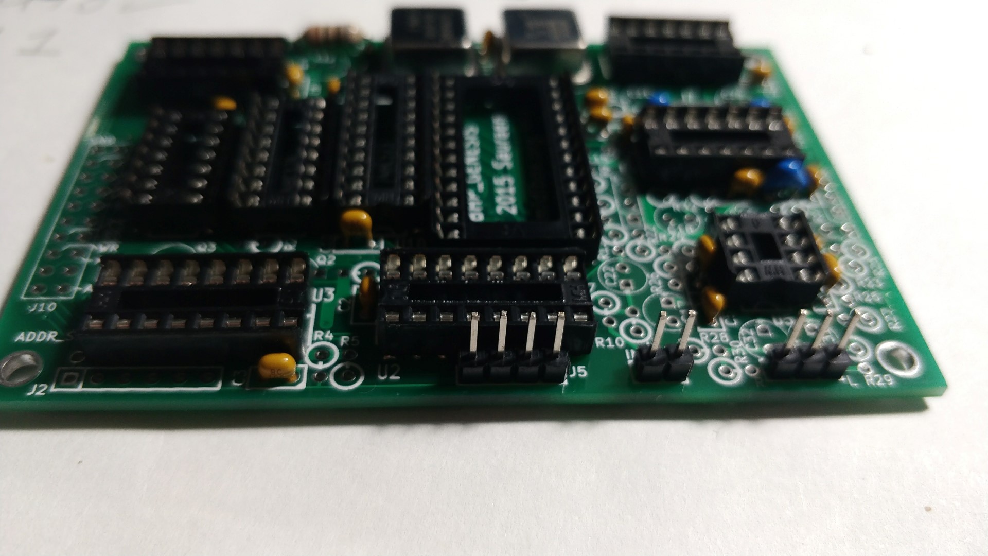
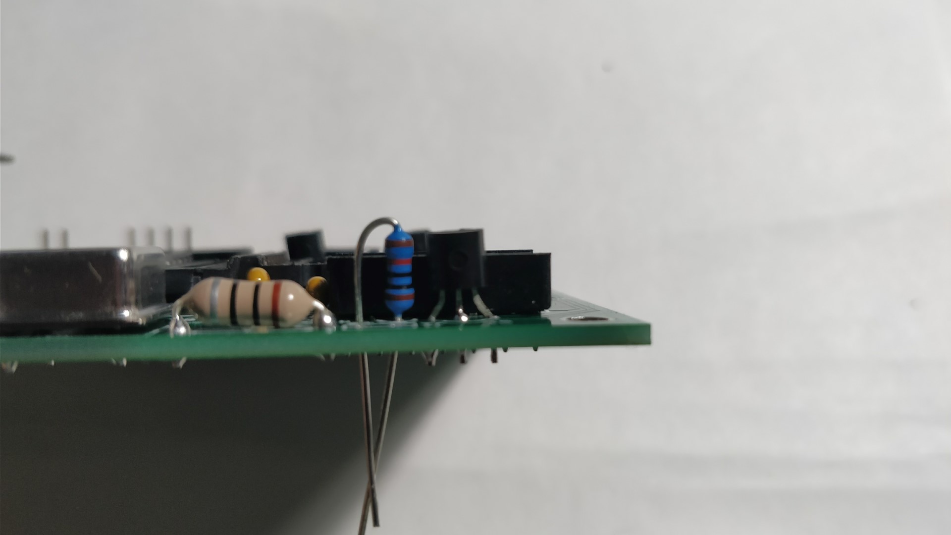
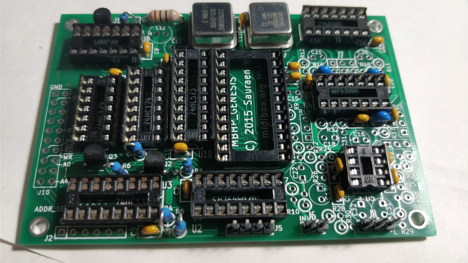
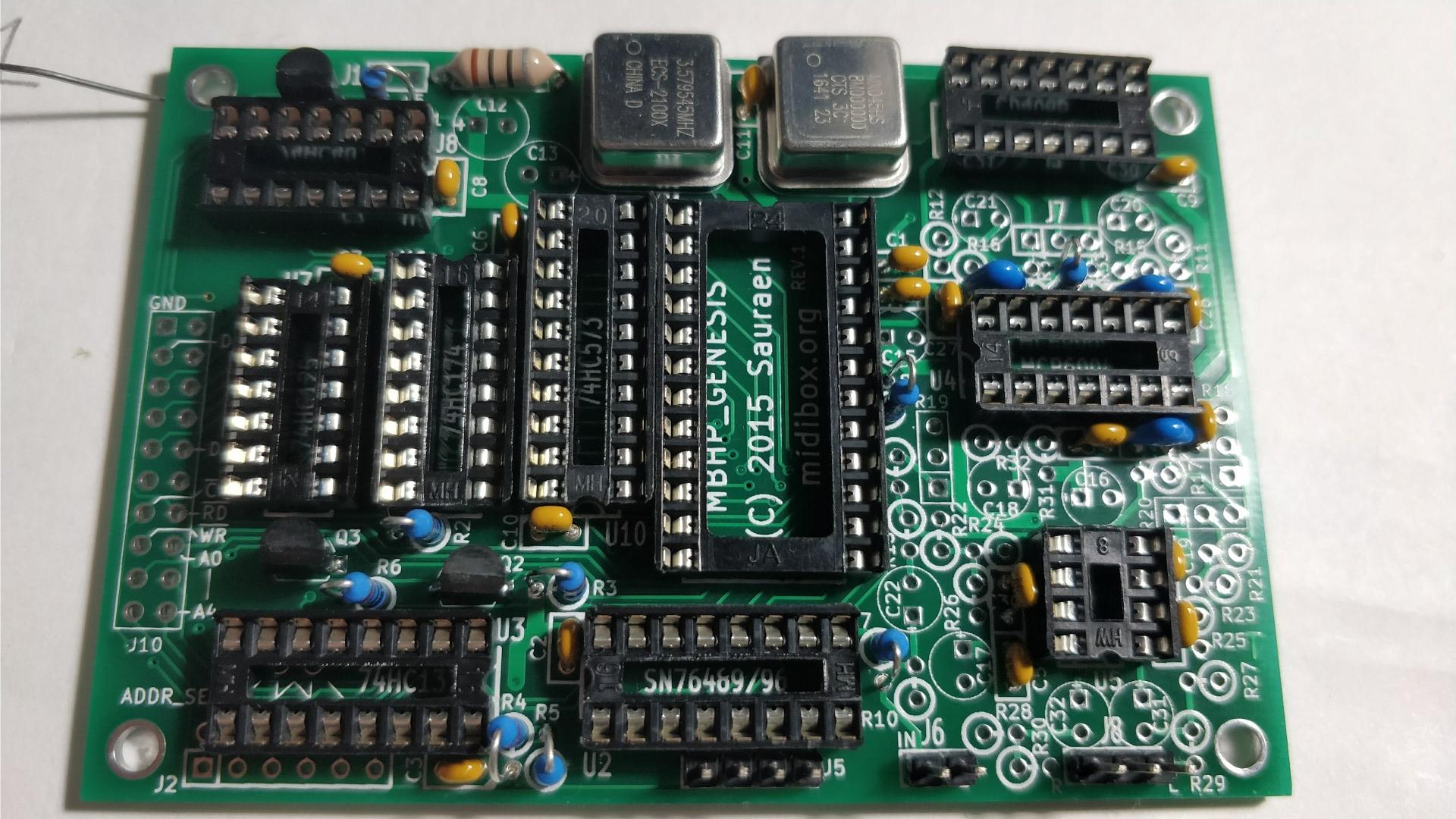
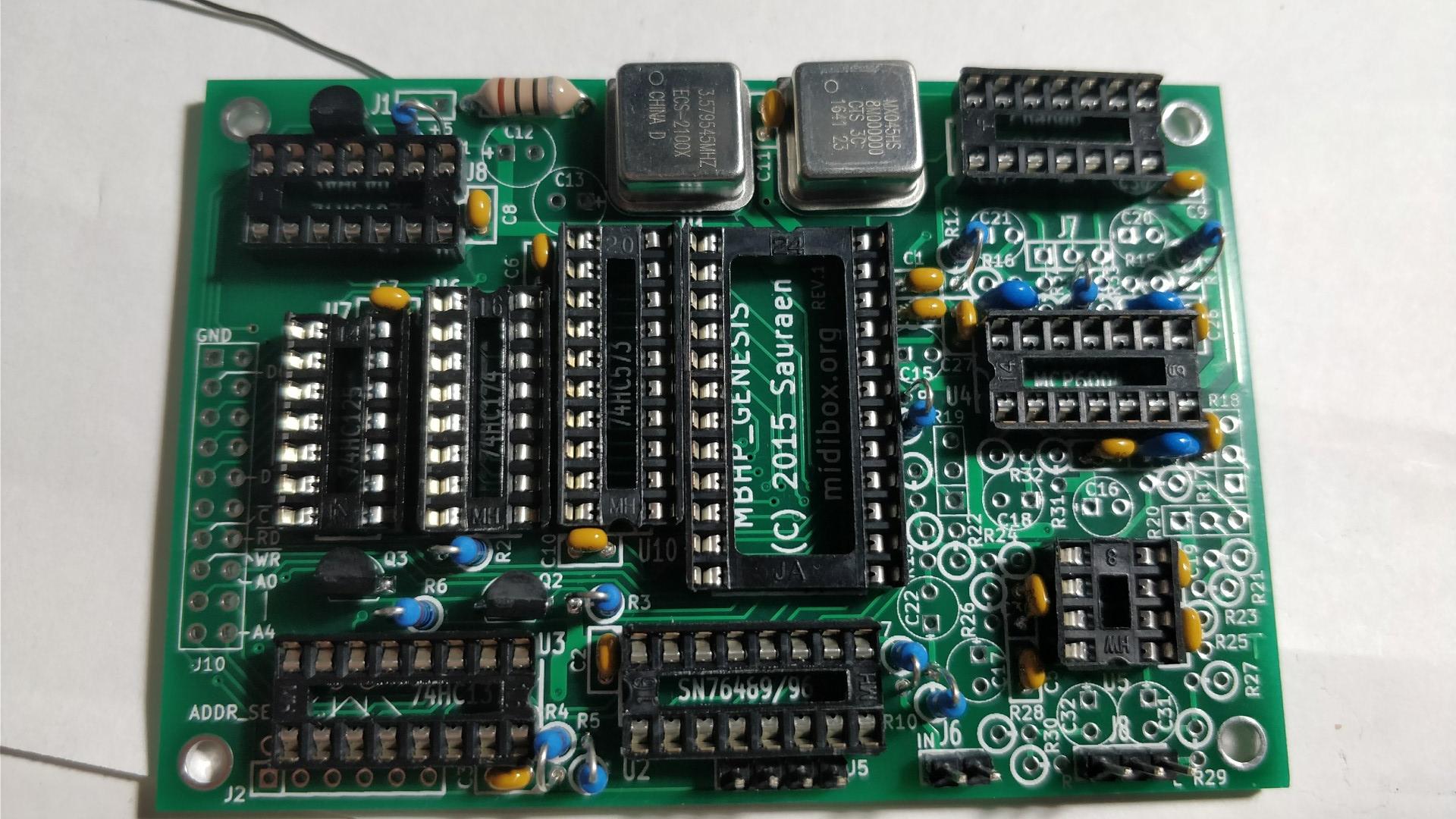
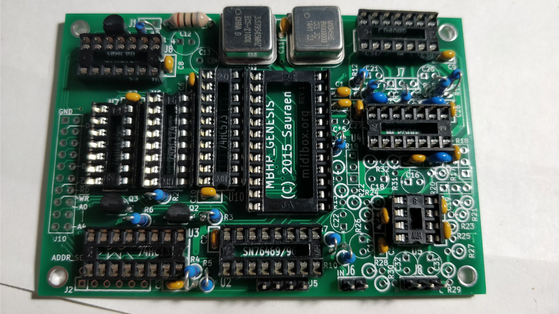
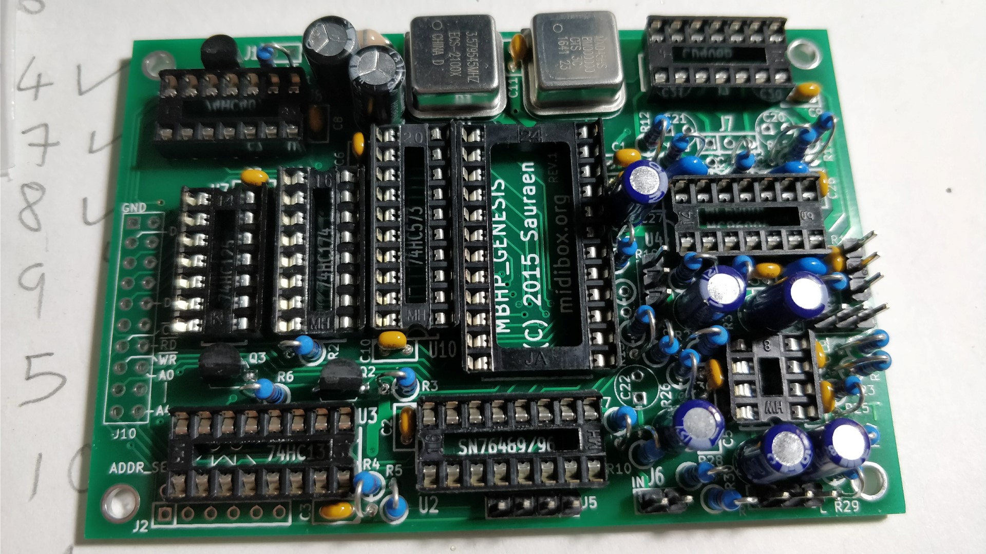
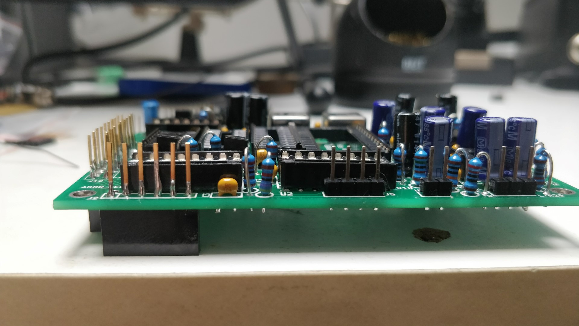
Step 8: Building the first Genesis Module. Since each board has a different address select configuration, we must read the wiki section: J3: ADDR_SEL "On board 1, stuff U3 and its bypass capacitor C3, but don't connect anything in J3." Start with by soldering Capacitor C3 0.1 uF. It helps to write down a list of the component refernces and tick them off as you go. Next populate the remainig 0.1uf capacitors C1-C11, C14, C19. Populate C29, C30 100 pF. Populate C26, C27, C28 1nf. Populate C23, C24, C25 180 pF. Mine were blue and slightly taller. Populate Inductor L1 10uH. Populate 16-pin 0.3” DIP IC sockets, [U2], [U3], [U6], take care for orientation Populate 14-pin 0.3“ DIP sockets [U4], [U7], [U8], [U9] Populate [U5] 8-pin 0.3” DIP socket Populate [U10] 20-pin 0.3“ DIP socket. Populate [U1] 24-pin 0.6“ DIP socket Populate Y1 (through hole) or Y3 (SMT) 7.67 MHz (or 8 MHz) oscillator depending on which OPN2 you will use. Populate Y2 (through hole) or Y4 (SMT) 3.58 MHz (or 4 MHz) oscillator at desired PSG frequency. Please take care of orientation, the corner of the crystal goes in the top left corner. Solder the SIL Headers for J5, J6, and J8. Solder Q1, Q2, Q3 small-signal N-channel MOSFET. See Sauraens note on the mosfets. Next up is the resistors, bend one lead 180 degrees so you can mount them vertically. The resistor itself should sit on top of the circle on the silkscreen, the lead bent lead will go through the other pad. Solder R1, R3 10k ohm Resistors. Solder R2, R6 1k. Solder R4 2.2k resistor. Solder R5 47k resistor Do not populate R7 if you are using a SN76489 as theres no audio input. Populate if you are using a SN76494/SN76496. ( I populated it by accident and removed it later.) Populate R8, R9 2.2k if you are using a YM2612, otherwise Do Not Populate. Populate R10 1.5k resistor. Populate R11, R12. Use 22k for YM2612, 47k for YM3438 Populate R15, R16. Use: 47k for YM2612, 10k for YM3438 Do not populate R14, R33, R34 Populate R13, R17, R21, R22, R25, R26 47k resistor R18/R19 are for the 10K Potentiometer. I soldered SIL Headers for these, otherwise you could solder the wires directly to the board if you wanted. R20 is the 10K potentiometer for the PSG. Again I used a SIL Header. Solder R23, R24 220k resistors. If you want a louder PSG, reduce the value. Solder R27, R28 100k resistors. Solder R29, R30 220 ohm resistors Solder R31, R32 10k 1% resistors. C12, C13 100 uF electrolytic capacitors. Solder C15, C16, C17, C18, C31, C32 10 uF electrolytic acpacitors. Solder C20, C21, C22 10 uF bipolar electrolytic capacitors. The Genesis modules need to be stacked using the stackable arduino headers with 15mm long pins. These headers with extra long headers can be hard to find, here they are on Aliexpress, play-zone, funduino. The top of the first board is facing left, with the pins sticking through, and the connectors will be flush against the bottom each board. For the bottom board you could use an SIL header with long pins You will solder the pins at the top side of each board. The following image shows PCB 1 on the left, PCB 2 to the right of PCB1, PCB3 to the right of PCB2 etc.. Please note that I used SIL headers instead of Aruduino headers for the headers on the bottom board PCB4, as you can see in the 2nd pic below: This is so that the black plastic won't be taking up unwanted space. I couldn't find 3 and 2 pin Ardunio headers so I cut up a 6 pin like so. Solder the ardunio headers at J1, J2, J7, J10 Next, trim the pins on the aurduino headers to the same height as the SIL headers, so the connectors for the wires plugging into them will sit flush.


-
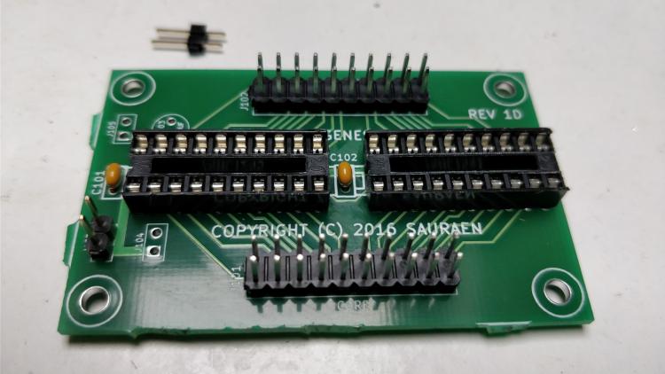
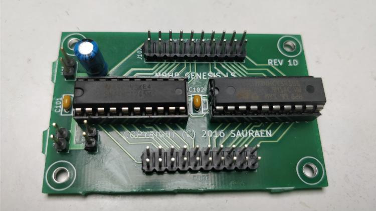
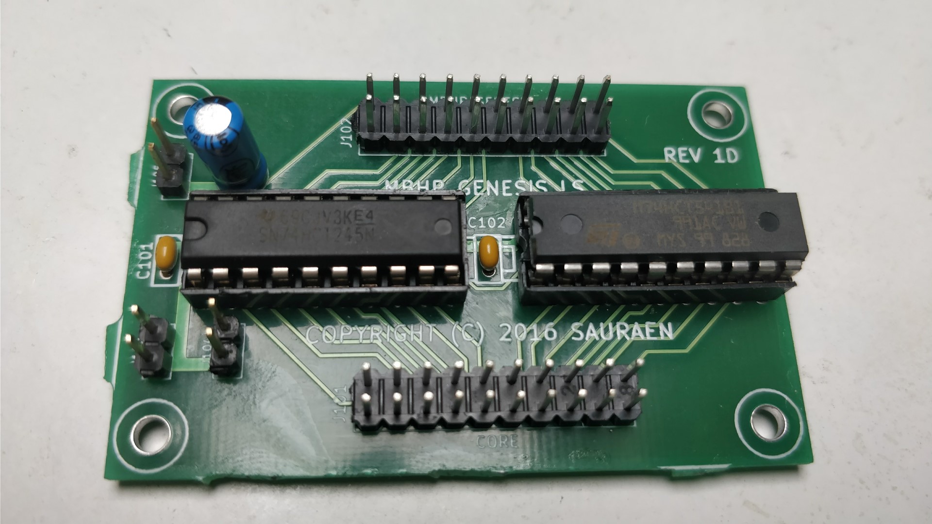
Step 7: Building the MBHP_Genesis_LS module. As always start with the shorter components, in this case the two 0.1 uF ceramic capcitors, C101, C102. Then solder the IC Sockets, and Pin heders. Ensure the IC sockets are facing the correct way according to the silkscreen, left in this case. Finally solder the electrolytic capacitor C103 ensure the polarity is correct. The longer leg is positive and goes through the square pad on the PCB, there is also a + sign marking, (it looks like a minus but the circle line indicates its positve. Next install the 74HCT245 in socket U101, and 74HCT541 in U102 ensuring they face left.
-
So how do we go about flashing the bootloader, and uploading the Hex File? I have the ST-Link USB Driver installed and the Virtual Com Port Driver. However the waveshare core is not detected in the ST Link Utility. Or in the ST Flash Loader . I've tried it with the switch set to System and to Flash.
-
My waveshare core came from AliExpress today. Will there a separate firmware for the Andy Seq or will it be incorporated into the existing firmware? Thanks.
-
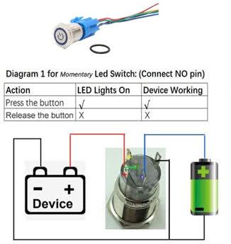
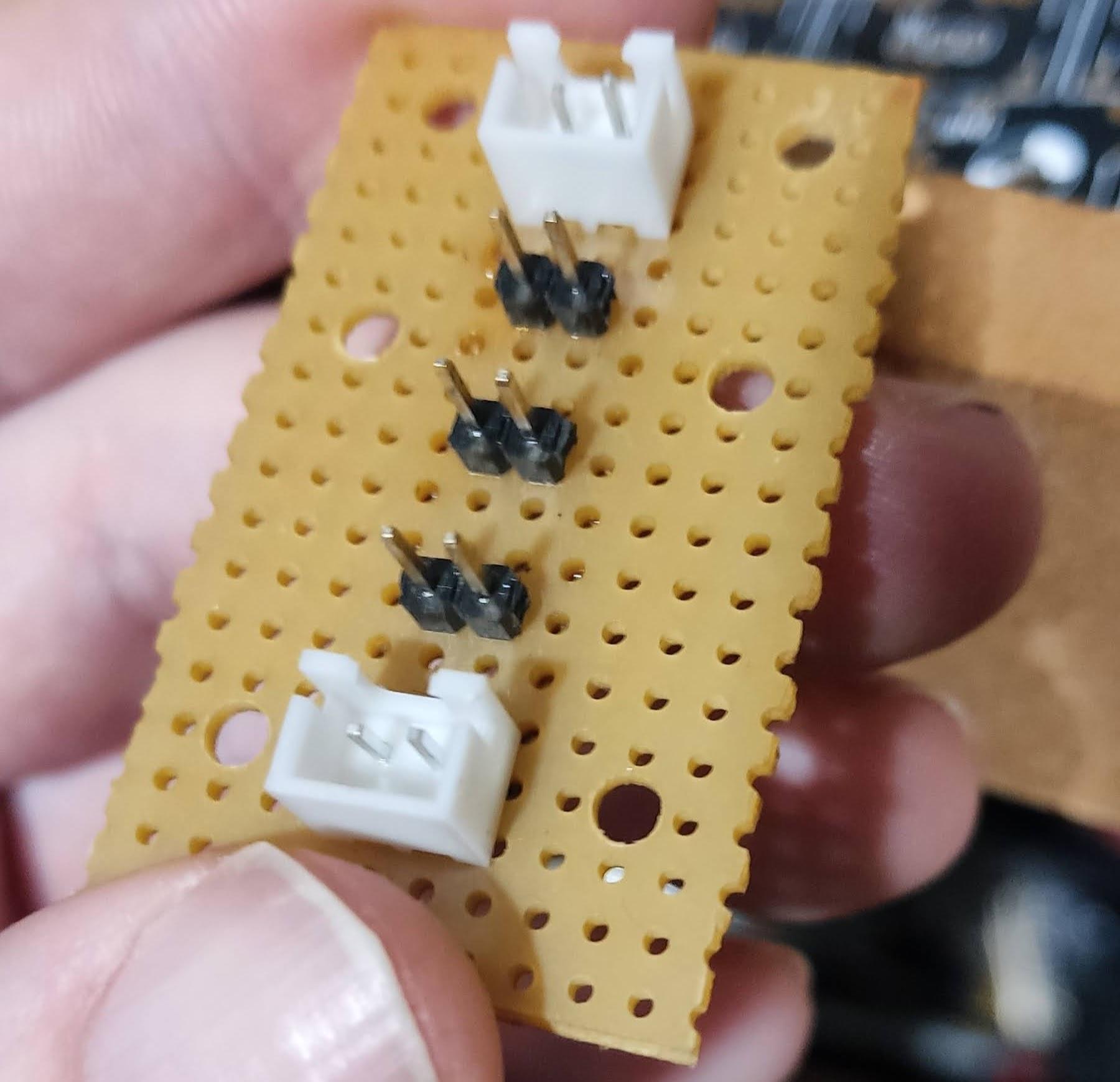
Step 6: Building the Power Supply. For the Power Supply, I'm keeping things extremely basic. I use a 5V 1.6A power plug (wallwart) I bought from Farnell, with the center pin positive. I also bought a panel mount DC socket with ~8mm width to fit the 8mm hole in the Rear Panel. It uses a barrel size of 2.1mm a to fit the plug on the power supply. I am using a generic Panel Mount Latching Push Button Switch with 16mm thread size to fit the 16mm hole in the Rear Panel. I bought the switch with the wiring harness included as it makes it easier to connections the wires by colour. The colour codes may vary depending on which switch you buy! I crimped the wires on the harness with JST-XH crimps due to the thicker wire gauge and used 2 JST XH-2A male connectors on the power distribution board as shown below. For the cables going the Core Module and MBHP_Genesis_LS level shifter board, I used Dupont style crimps and SIL connectors and smaller wire guage. I recommend buying this crimping Set as it includes everything needed, the Crimping hand tool, the Dupont & JST crimps and connectors, and even some ribbon cable. For crimping the JST-XH and Dupont crimps please see this excellent guide on YouTube. If you would like to add some sort of circuit protection yourself go ahead, I wasn't quite sure how to go about it. From the wiki: " The output of one switching regulator was used exclusively for the front panel, while the output of the other was sent to the core and the Genesis boards. " The Power Supply must feed the 3 Modules, the STM32F5 Core, the Quad Genesis Modules and the Front Panel as stated in the wiki, and also the LED for the power switch if you buy one." For this I built a simple parallel circuit or distribution board on veroboard, with 2 male JST XH-2A connectors on top and bottom and 3* 2-pin SIL Headers for powering the Core, and Level Shifter boards soldered in between. Top side of power distribution board: Underside of Power Distribution board: I also drilled 4 holes into the veroboard which we will use to mount it with M3 screws inserts and screws later. Here's how I have the board wired up: **Important** push the dc socket and latching switch through the Rear Panel before soldering! The common wire C is soldered to the positive terminal of the DC Socket. I used a spare wire which is soldered to the negative terminal of the DC barrell and is connected to the negative terminal of the top female JST XH-2Y connector. The NO Normal Open wire is connected to the positive terminal of the top JST XH-2Y connector. The LED- wire goes to the negative pin of the of the bottom female JST XH-2Y connector. The LED+ wire goes to the positive pin of the bottom female JST XH-2Y connector. This is wired so that the Power LED on the latching switch is not illuminated until you push the switch and close the circuit. For the wires connecting to the DC Socket I used heat shrink to insulate the terminals. Next step is to connect the 1st SIL header (2nd Header in the row) to J2 on the breakout board of the Core. Now we will power on the core without using the Micro USB or Mini USB cables. Switch on the power, or plug in the wallwart and ensure the Core and LCD display boot properly.
.thumb.jpg.05fb5447fb857ff41127ece5d0dc449c.jpg)
.thumb.jpg.e43abb736f4e7bd97a30321d49d79bc9.jpg)

.thumb.jpg.7c945f27c1d3cb22939cdfc7f1e9c448.jpg)
.thumb.jpg.9d60699f384004b5c14c793088d0c6ec.jpg)
-
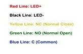
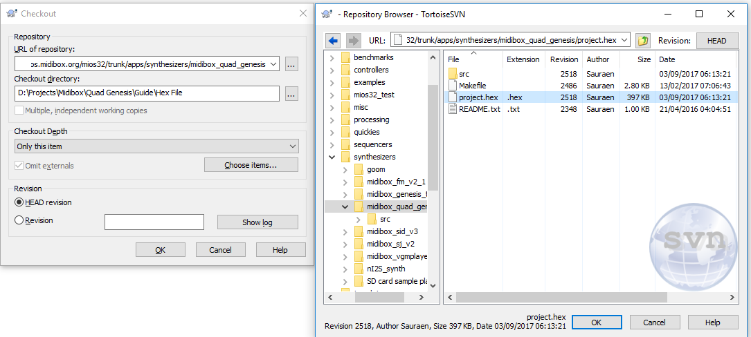
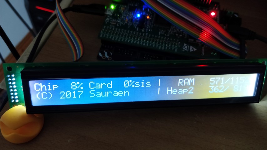
Step 5: Uploading the MIDIbox Quad Genesis application / hex file For this next step you will need an SVN client to download the MIDIbox Quad Genesis hex file to your computer. I like to use the GUI over the command line so I use Tortoise SVN: https://tortoisesvn.net/downloads.html After installing Tortoise SVN, right click on a folder you would like to download the hex file to, and left click SVN Checkout. Paste the following URL under "URL of repository": svn://svnmios.midibox.org/mios32/trunk/apps/synthesizers/midibox_quad_genesis Press the 3 Dots and select the Project.hex file. Click okay, and then choose the Directory you want to download the file to. Then click under Checkout Depth, and change it to "Only This Item", to prevent it from creating the directory layout. Now its time to upload the Hex file. Connect the STM32F4 Core to a computer using the micro usb cable AND the mini USB cable. Download and Launch MIOS Studio 2, you will need to have the Java Runtime Environment installed also: http://ucapps.de/mios_studio.html MIOS Studio should automatically detect the Core on startup. Make sure the MIDI In and MIDI Out Devices say MIOS32. Click Browse to locate your hex file and add it. Click start to upload the Hex File. If the Hex File uploads successfully you should see a screen like this on the LCD Display:

-
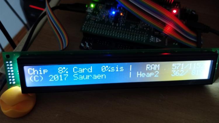
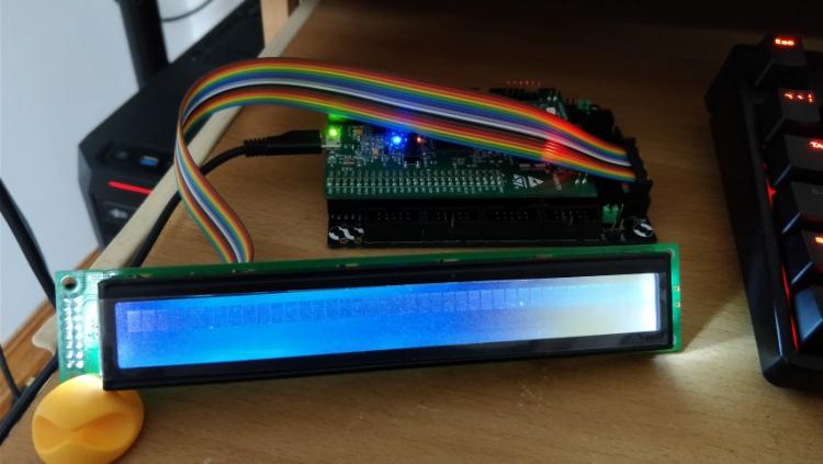
Step 4: Adjusting the Brightness of the LCD Display Plug the Core into a USB power source by connecting the Micro USB cable. Turn Potentiometer P1 (next to LUM1) clockwise to increase the brightness or luminance of the display using a screwdriver. Turn Potentiometer P2 (next to CONT) clockwise from a fully anti clockwise position to increase the contrast of the display. If you can only see character blocks then the contrast should be adjusted so that the character blocks can be barely seen: If you can see the Bootloader screen with text then adjust the contrast to your preference.
-
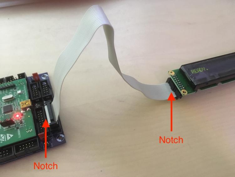
Step 3: Connecting the 2x40 LCD Display First step is to solder a 2x8 DIL Header to the LCD Display with the longer pins underneath the LCDs PCB: The connectors and cable should be orientated like in TK's picture below: Please note that the cable at J15A of the (Core Breakout Board) goes through the connector to the left in the picture, then folds backwards and goes under the connectors clip and goes to the right. On the opposite end the cable is NOT folded over at the connector on the LCD and no clip is used. To see how to physically attach the connectors using tools please consult Jim Henry's guide, but do not pay attention to the connector orientation as its an older guide: http://www.midibox.org/users/jim_henry/building_a_midibox_lcd_cable.pdf Tip: I find using a Bench Vice to close the connector works best.
.thumb.jpg.7f3b9f96ba7bcadd00db33ef539511ff.jpg)
.thumb.jpg.794a0d72232fc39e9f0d1707ed1a5f1e.jpg)
.thumb.jpg.b7b631c92313bb7d6bc0a19294fd4267.jpg)
.thumb.jpg.dcae5204ae1d85f1d091dca64d87f9a1.jpg)
-
Welcome to my guide! The very first thing you should do is read the MIDIbox Quad Genesis section on the wiki as much as you can: http://wiki.midibox.org/doku.php?id=midibox_quad_genesis Especially the MBHP_GENESIS, MBHP_Genesis_LS and MBHP_FP pages. If you would like to build the wooden case before soldering the electronics then please jump to this post: Step 1:Installing the MIOS32 Bootloader on STM32F407G-DISC1 This is already explained in the STM32F4 Based Core page on ucapps.de. Simply scroll down to: http://ucapps.de/images/bullet.gif Installing the MIOS32 Bootloader and follow the guide. Remember that the Micro-USB cable must be inserted upside down on the left hand side of the board. Step 2: Soldering the Core STM32F4 Breakout board: This is also already explained on the STM32F4 Based Core page on ucapps.de Simply scroll down the page further to: http://ucapps.de/images/bullet.gif Soldering Guide and follow the instructions. After the soldering is complete please make sure to set the Jumper at J15_S to 5V, by connecting the 2 pins on the left hand side with the jumper. This will feed our LCD display with 5 Volts. If your LCD Display uses 3.3V, then put the jumper to the 2 pins on the right hand side. /edit TK: check if we can edit this posting
-
Awesome work guys!
-
Finally got around to doing this, i used have a crackle from time to time in the audio output using an c64 power brick, but this mod seems to have fixed it! huge thanks to altitude for the mod, and to jaytee for the awesome tutorial!


.jpg.c19e2f6e1598051c86a19f838e63c8a4.jpg)


.jpg.d2858350a5234690d594a3722117dc15.jpg)
.jpg.84b7e76575b3512e20e9b967cfca7de7.jpg)


.jpg.2c19904b6578d11d82111c21cd9844e1.jpg)
.jpg.e89bf382211f823cf022b2301ada6495.jpg)


.jpg.3a66f05fdadc8b712d9ad91ace7ab92d.jpg)
.jpg.e80ec083550f9cf3521366674a7e4fd4.jpg)
.jpg.6d3efc55b26fbbea95bc72aad033e425.jpg)
.jpg.81cd34eaa057cc19247dcf773ac80b7a.jpg)
.jpg.baad0840c3063af2ac311ee8c0b8fd86.jpg)
.jpg.31566ebc41bc976ae9292c330fa9e3a7.jpg)
.jpg.2e3be0955b13bbc26415d4e56e2040dd.jpg)
.jpg.3574c711edcf109aa1b138c8ec6f4d31.jpg)
.jpg.d90c914d99ab1919196ff094eeb9ad59.jpg)
.jpg.d2b48dbc0428b42f11fe0b3aff228766.jpg)
.jpg.a7176aea6907d29d2243cd85059d8452.jpg)

.jpg.bad0d8d2f508d18a03026ac755d64963.jpg)


.jpg.6962deb10456218f3b7ccb74cf509064.jpg)
.jpg.71e1c6530219124495d557538ecfad13.jpg)
.jpg.0f29fd67e9681b4b839a56dcf9ba43c1.jpg)
.jpg.446ffe6ed130e15759804e46aeb42a2e.jpg)


.jpg.bc3aec2dfeb0132039c573b8500dd8f6.jpg)
.jpg.71457db0b0e0de9c946a2f625869c2bf.jpg)
.jpg.028fff405550ff5c2ad5c43b634fbc84.jpg)
.jpg.6a55e08aadf279586b825c43c65582c1.jpg)
