

latigid on
-
Posts
2,516 -
Joined
-
Last visited
-
Days Won
147
Content Type
Profiles
Forums
Blogs
Gallery
Posts posted by latigid on
-
-
Did you change the device ID to 1 when flashing the .hex? You should be able to communicate with the Core that way. Or how did you upload the .hex file?
-
What is the device ID printed on the PIC? Maybe the two both have the same ID and hence communication only works with one of them? You can try to disconnect the known-working one and see if you get input.
If you need to change the IDs there's an app (.hex) for that that you upload with MIOS terminal. Thereafter reload your program.
-
Nice!
-
Could be a buffer size thing but you should start a new topic, try to e.g. record the output with MIOS Studio (set up the router) or through a utility like MIDIOX or so. Try also to delay the transmission rate?
-
Here you go! Please don't short the (typically unpopulated) J3-6 headers for (+5V supply buss).
The next run of PCBs will have the polyfuse added, thanks Adam for the research and suggestion!
-
Hi Manu,
Great that you're nearly done! Thanks a lot for looking through the other troubleshooting ideas first.
For this one:
Just now, manu said:3) I swapped the cables from the working display and defective display. The defective display behaviour is unchanged.
Does it mean that you removed the cables from the OLED end, and the known-good J15 port and cable also showed the same behaviour with the "right-hand" OLED? Normally I would expect that the cable had a missing connector or shorted cable. It might be worth building a brand-new cable if you have the connectors and ribbon handy. You can also check the Core module IC2 and resolder the pins.
Do you notice any different behaviour if you just connect one OLED at a time? Also, how are you powering up? You might try a phone charger USB or hub with more power available.
Just now, manu said:2. LED matrix does not work anymore
Maybe a cable got loose? There was one IDC8 connector that didn't fit well. Otherwise, I'm not sure what to suggest if everything else is running. Did you check with the correct _L/_R NGC and the correct SEQ HWCFG?
Best,
Andy -
Not 100% sure how the drum track architecture works, but as a hack could you configure your drum instruments (notes) one octave higher then transpose the whole track back down one octave? My guess is that the MIDIbox relies on that empty note data for something e.g. a placeholder.
-
The midiphy A1 expander sets an offset for this reason. You can also transpose your SEQ track...
-
You could add feature requests to
http://midibox.org/forums/topic/13137-midibox-seq-v4-release-feedback/?page=61
I'm not sure if MIDI channel makes sense because it's part of the track events/setup. But you can ask!
I think mute/solo was on the list for a while.For button assignments, you can freely choose any function you see in the HWCFG file. I don't know if you can reassign the encoder presses, or if that's generally a good idea vs. leaving them reserved as accelerators.
-
Maybe the AOUT isn't calibrated or the Moog uses something different than 1 V/oct? I remember something like that for the Voyager or similar.
What AOUT setup are you using?
-
Congrats #27! Looks like a groovy colour-scheme and thanks for the kind feedback!
EDIT and beer (?) !


-
Great job #26! :) That's a phenomenal achievement for a first DIY.
-
Great work! Cool sounds and a nice groove.
-
Glad you could fix it!
-
-
As well check the polarity of the diodes and that no LED legs are broken.
-
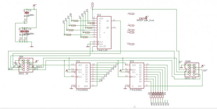
That's the SRIO chain, good luck!
-
Maybe the resistor network is soldered the wrong way around? Have you checked the cables for short circuits? Are other boards connected in the chain? What MIOS events do you see with set debug on?
-
Hi Robert, what resistor network is installed?
-
Sorry, the bottom of the case is welded by the corners.
Btw, the seq_r.NGC file was completely the wrong thing. https://github.com/midibox/mios32/pull/8 but still needs to be approvied by TK.
If you post a picture of the finished unit you get your serial number!
-
The clear ones are on midiphy if that helps.
-
If you can't get a vice, this is also a nice sort of tool:
https://www.dicksmith.com.au/da/buy/bourne-electronics-idc-plug-crimper-crimp-tool-t1540/
Vice is nicer though, as once the cable is in and the connector is in place, you can control the angle of the cable to avoid shorts and overlaps.
-
Awesome to hear! Most of the time it's the cables ;-)
For seq_r.ngc testing, it's possible that .NGC file is buggy. I was baffled as to why the hardware would be fine in one config but not the other. It's something to check.
For now, it is of course fine just to test with the _l config file and swap boards around for the finale.
Sorry about the bugs and hope to see the SEQ running soon!
-
 1
1
-
-
Should work, just remember to use the correct SEQ HWCFG file. Like the .NGC, the left/right suffix refers to the position of the JA board. You can also add boards one by one for the _NG testing, good idea.
It would even be possible to make a custom .NGC based on the _R file and adjust the shift register addressing to test lemec _R first in the chain. You need to adjust the positions of the shift registers because there are three extra ones (that go off to the JA matrix) before the "main" BLM and encoder scanning ones.
Maybe some cables are twisted? They should run in a nice chain, correct? Do all of the IDC shrouded header notches have the correct orientation?
You might consider reformatting the SD card or reflashing the app.
-
1
-


Troubleshooting midiphy SEQ v4+
in MIDIbox SEQ
Posted
Awesome work, thanks for the update! Your serial number is waiting :)