

latigid on
-
Posts
2,516 -
Joined
-
Last visited
-
Days Won
147
Content Type
Profiles
Forums
Blogs
Gallery
Posts posted by latigid on
-
-
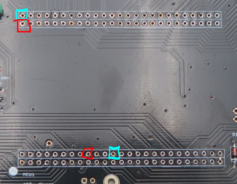
Here is the "minimum system" with +5V in red, 0V in blue. Also PA11/PA12 as before. Try pulling off the diode too!
-
There is no explanation other than a weird TVS diode pulling something up/down. I would try with that removed. You could even only resolder the waveshare with pa11/12 and the +5v pins. Can provide info when I'm back home or you can check the waveshare schem.
-
No it wasn't. Peter is into the code now and would know if it can be implemented /reimplemented.
-
Also that the waveshare is off, could we see that too? E.g. was the crystal desoldered, the jumpers removed, but resoldered correctly for instance?
-
15 minutes ago, Hawkeye said:
@latigid on: could we try to trace the USB signal pins from the STM32F4 microprocessor right to the USB port on the LoopA core? Which connections would need to be tested?Sure, already suggested:
R30 to PA11 (yellow)
R31 to PA12 (pink)
Other side of the resistors:
R30 to USB 3
R31 to USB 4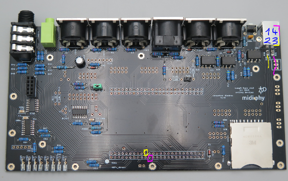
-
Soldering looks very clean! Was the v407 breakout actually soldered in? If so, impressive that you managed to get it out so well! If it wasn't soldered in, well then the pins probably never had good contact with the LoopA-Core PCB.
Other things: try desoldering the TVS diode and powering without it.
Also the (soldered -- brave!) optocouplers don't seem to have enough on them, would recommend a touch up. -
6 minutes ago, Antichambre said:
If you're already in track mode(only track button lit) and you press(short or long is the same) the mute button, both rows will shows the tracks mute(redundant), if you want to get back the track sel on the second row you must press track another time then track and mute buttons are lit, first row and oleds indicate the mutes, second row indicates the selection.
I think I notice this behaviour too and it could be improved!
What I would expect:
From SB Track or layers, press and hold SB Mute, the Sel row controls mutes, also displays on the OLEDs. Releasing SB Mute would revert to the previous Sel.Does that fit with your idea?
-
I think what I would expect is the Selection (Sel) row to always indicate the function indicated on the 8x selection buttons (SB). So if I am in Track, the Sel row should choose tracks 1-16/GxTy. Switching (click and release) to the mute mode will show the mutes. From Track, click and hold on Mute should allow temporary switching to mutes, then when released back to Track. For me, it seems somehow to get "stuck" so the mute SB stays on and the OLEDs stay stuck in mute.
I wonder if there is a conflict with option #9
QuoteWhenever a track or parameter layer is unmuted, it will be automatically selected.
This option can now be disabled in the OPTIONS page (item 9/29)or similar?
-
Hi Bruno,
My understanding of the selection buttons (around the datawheel) is:
click and release: change the selection row to that function
click and hold: temporarily switch to this function, when released it will revert back to the previous selection.Does it work that way on your side?
Best,
Andy -
1 hour ago, Altitude said:
Im not sure where to go from here.
Post some pics of the PCB to let another set of eyes go over it for something obvious?
1 hour ago, Altitude said:1. Power good. 5V and 3.3V where marked
2. rehit all joints on the header, no change
3. Orientation of TVS is correct
4. 22R resistors are fine
5. Tried various USB cables/multiple computersThere's not a lot to the USB but I would check/scope the line between the 22Rs and PA11-R30/PA12-R31. Do the header pins contact the MCU chip pins?
1 hour ago, Altitude said:Other observations:
- the app started once. This was with the mini USB direct to the core, i could not repeat this behavior
- I can no longer get the miniUSB to do anything, it will start the device since the power led will fade in and out but no USB devices show up
- nothing is coming out of the midi ports
- with the main USB connected, I get the upload request over USB and feed back when I send the hex but I cannot send any other console commands to the bootloader (i.e."help" does nothing)
Does your core = the STM discovery core? As in does it take the same bootloader?
The bootloader is the normal MIOS one. When you "reflashed" was it with boot hold or over JTAG? It would be worth trying a) to upload any MIOS software e.g. _NG to see if that sticks or b) to wipe the chip and start again from bare metal.
Is an SD card inserted during any of this?
Does the 3v3 rail remain stable during startup?
Do you see any LED or OLED activity?
-
Check the 22R resistors R30/31, TVS diode. Check the USB pins PA11 PA12 make it to those resistors and the MCU chip (2x2x25 pinheader soldering). Check for shorts to 0V. Check PA10 (USB ID) is floating and no jumper is in J20. Check the USB socket.
You might also try reflashing the bootloader with hold mode (JPA0, needs at least R102 mounted) or even via JTAG if it got corrupted somehow.
-
Hehe, Peter does indeed have a soothing voice :)
Maybe check that your Waveshare 407v is set to Boot Config: Flash?
Best,
Andy -
Would have to leave Peter to answer specifics about the LoopA firmware but I will see what I can answer.
19 hours ago, momelq said:Hi Peter,
For the pattern analyzer, I am thinking about like here:
https://www.link.cs.cmu.edu/music-analysis/
but I will need time for some tests and simulations, before I can give good suggestions.
However, here some more and simpler feature requests :-)
- cosmetic change Tempo Setting: swap Faster/Slower buttons, as I would expect faster on the right side.
I think I suggested that one too :)
19 hours ago, momelq said:- Undo last record / overdub
Might be tricky as the LoopA would have to track when things were last armed. But if there is a sensible way to do it and it's possible to code it I'm for it!
17 hours ago, jplebre said:Hiya!
I want to say I absolutely love the work done for both the SEQv4 and the LoopA. Although I'd love to build both, space is a factor and the SEQ is too big.I have a question about LoopA (although I think I know the answer by reading the manual):
- Does it support step-sequencing style (either playing on a keyboard or entering/dialing a-la Seq4) input? The use case would be "I am really really bad at playing the keyboard and just want to enter it one note at a time"
It's a real-time MIDI recorder/looper so a different interface than a step sequencer. You still have to enter the notes by playing them but you can quantise after.
17 hours ago, jplebre said:- Maybe I got this completely wrong, but is it possible to somehow enter "events" in a scene (e.g. to move to another scene). I guess the use case would be "I want all my scenes to flow like a song and I finished the arrangement. at step 32 there's an event that triggers scene 2. at step 16 of scene 2 there's an event that triggers scene 3 - which is a duplicate of scene 1 except at step 16 it triggers scene 4". This is reminiscent of Polyend Seq's links
No "song mode" at the moment as far as I know. But maybe it will be added at some point.
17 hours ago, jplebre said:- Would the midi files also have the same naming convention as they are displayed (eg. 1A, 1B, 1C, 2A, 3A, 3B, 3C etc.) for quickly import into a DAW. (or to splice from a DAW into the SD card to be played by the LoopA?)
No MIDI export at the moment but it's on the list. I don't know the naming structure.
17 hours ago, jplebre said:- I've seen someone requesting different lengths per track (eg. for polyrhythms or system music) is this a possibility in a future upgrade?
On the list!
17 hours ago, jplebre said:I'm really keen on jumping on a LoopA although I'd have to figure out how to enter step sequences (and polyphonic ones at that). I could edit the midi to heart content but that's too slow for my specific workflow :(
What is your specific workflow? If you want to edit individual steps then a knob-per step is best, hence the SEQ. If you want to "noodle" a jam and tidy it after, then LoopA.
17 hours ago, jplebre said:Also, my final question for now - non LoopA related - can the SEQ v4 work with just the master module and one section? could it be made to work on a cut down size?
No, the UI requires both 40x2 OLED displays and a knob/"GP button" per step.
17 hours ago, jplebre said:This is brilliant, looks amazing, the UI looks like it had many many hours to get the UX right.
Great job!
JThanks! All was based on Peter's initial concept with some minor additions.
Best,
Andy -
We're making good progress! It's a fancy new app with a fancy new display and fancy new other things. :)
-
Hi Steve,
Please refer to the BOM e.g. https://www.midiphy.com/en/shop-details/137/47/midibox-seq-v4-lh-full-essential-kit-
This is the whole "kit BOM" but each PCB also has its own BOM page for easier reading, plus you won't get confused with the coded "shop names" of the PCBs. There you can cross-reference all parts with the silkscreen names on the PCBs.
You could in effect use the slightly longer pins for everything. I think the "standard" pins are only used for jumper headers etc. Where it's important is interconnecting the lemec and plate PCBs with through-PCB headers/sockets. A "standard" header length works but might not give quite the right contact, therefore slightly longer ensures a better connection.
Have fun building!
Best,
Andy -
Hi Robert, great!
I was thinking of suggesting that you trying another card, but you said you tried two and formatted already so I didn't want to patronise you. I can only think that certain card models don't work properly and we also notice that in the SEQ. I don't think there is an upper limit and I typically use 2 GiB SanDisk ones myself. You could try the 8GiB one in the LoopA for a true test of intercompatibility :)
Have fun!
Best,
Andy -
Hi Robert, I've seen it happen that the SD slot can be soldered with too much heat and this can kill things. How was your soldering of it?
Check for continuity back to the 407v breakout pins, here's a convenient pinout of the SD card from the top:
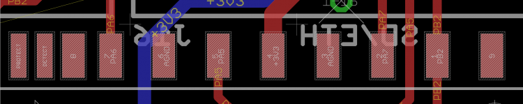
NC NC NC PA6 0V PA5 +3v3 0V PA7 PB2 NC
I would suggest not to solder the three leftmost pins. You can also check for flux residue or shorts there.
Care to upload photos of your work?
Best,
Andy -
Glad to hear! Enjoy your sFM! You can get some cool sounds out of it but I found programming is not 100% straightforward.
-
 1
1
-
-
Check back to the Core pin and whether the PIC is socketed properly or has adjacent shorts, check the interconnection header pins/socket.
-
Yep, the L4 superellipse caps were very popular and we sold the last sets over the weekend. More caps inbound but will of course take their time at the moment.
Ordering a full kit would be possible if you were happy with the old clear-style caps, still some of those around.
For LED soldering, you can just mount the LEDs flush against the PCB. They will not fit through the case cutouts anyway. One user wrapped his panel LEDs with heatshrink (Schrumpfschlauch) to block light from neighbouring positions. It's a personal preference though; some like the effect of LED mixing.
Best,
Andy -
Mouser 517-929834-07-36-RK is one of the longest "standard" headers but only single row. Check the datasheet on the Mouser page and you will find other parts. None of the longer dual-row header 929710 are stocked apparently. But you could use a pair of single-row strips, which is what we do for the LoopA.
-
2
-
-
Maybe then check the data signals reach the shift register? You can cross-reference the PIC Core and DOUT schematics:
http://ucapps.de/mbhp/mbhp_doutx4.pdf
http://ucapps.de/mbhp/mbhp_core_v3.pdfIf in doubt you can also disconnect the sandwich and run wires directly from the Core pins.
-
Pics are a bit blurry, but it looks like the LEDs have the correct orientation. You should be able to scope a (probably) 1/8 pulse on the LED
cathodesanodes if that column's LED is illuminated. Likewise, you should see an alternating (but up to 1/8) pulse on the transistor base. Do the transistors follow the expected pinout?When uploading the hex file did you specifically choose the sammich one or "normal" MIDIbox FM?
-
Can you get any normal LED function? Touch up the soldering on everything to do with the LEDs (pin headers, ICs, caps, resistors etc.), also check LEDs have the correct polarity .

MIDIbox SEQ V4 Release + Feedback
in MIDIbox SEQ
Posted
Would have to try it some time I still don't have my SEQ mounted in its case ; I think the UX idea with illuminating the respective track/layer SB LED seems logical but I haven't played with drum tracks enough. Another one that was intended to be developed was the mute/solo display rather than doubling up on redundancy.
An obvious question is how forks in the software are managed if they diverge from the main branch and only Thorsten has "full" commit privileges. But that is a discussion for another thread probably.