

latigid on
-
Posts
2,524 -
Joined
-
Last visited
-
Days Won
149
Content Type
Profiles
Forums
Blogs
Gallery
Posts posted by latigid on
-
-
Hi Laurent,
That's probably it, there is no power supply to the OLEDs in this case and they are likely parasitically powered somehow.
Here you can borrow the jumpers from the v407 board:
https://www.youtube.com/watch?v=QaN26uzUA1A&t=3357s
I'm on holiday and the internet is too slow for me to find the tutorial step where the jumpers are inserted, but yes, you must connect the middle pin of J15_S to the 3v3 side.
Hope that solves it!
Best,
Andy -
Hi Adam,
Nice work, thanks for investigating! Could you share the exact part that you used?
Best,
Andy -
^Destpane is a variable, not a string. It's likely that there is a character limit on those.
-
Maybe use an oscilloscope to trace the LED signal? What is it connected to?
-
-
I like the idea @k2z3k0 !
-
Nice, thanks for reporting back! Now trim that contrast!

-
 1
1
-
-
Hi Laurent,
The part is correctly oriented as pictured, with the "vertical" bar closest to pins 1/16.
Bon courage!
Andy -
You'd need to reassign the pins, so use GPIO or a spare SPI for the SSD1206. Look maybe at the MBCV code?
-
Hi Laurent, feel free to post a clear photo/part number and I can check for you. The line should go along pins 1-2-3-4 etc. so the text of the part is readable with the line along the bottom.
Best;
Andy -
sr_dout_r1= is for 8x matrices
sr_dout_r2= is for 16x matricesI suppose you only use 8x8 matrices, thus keep sr_dout_r1 for the second DOUT.
Here's how you address one DOUT PCB:
sr_dout_r1=1
sr_dout_r1=2
sr_dout_r1=3
sr_dout_r1=4and here's how you address the next DOUT:
sr_dout_r1=5
sr_dout_r1=6
... -
POIDH!
-
Hi Adam,
Everything works, unless it doesn't
 . Yes, you should be able to use a controller keyboard and route the USB MIDI to another port for example.
Try here; in essence the hardware is the same, only the FET switch that senses current doesn't feature in the wCore/USB.
http://midibox.org/forums/topic/18906-usb-host-support-for-mbhp_core_stm32f4/#comment-165136
As noted, there are a few other jumper settings on the 407v breakout. I've read a few things in passing that require a different pull-up or so depending if the device is self-powered or not.
Have fun!
Andy -
Is the Korg self-powered? Did you jumper the +5V on the Core USB PCB?
I don't have time to investigate at the moment but you may also look into the jumpers on the Waveshare board. Read up on OTG handshakes; it might be that certain pull-ups or other data routines are required.
https://www.waveshare.com/w/upload/5/58/CorexxxV-Schematic.pdf
Best,
Andy -
Hi,
3 minutes ago, ssp said:n=<1..8>Specifies the matrix number which should be configured; it can range from 1..8 ( this i dont understand)
Defines the matrix to be addressed. You could have one matrix for 7-seg digits and another as a simple LED dot matrix. Each one needs a unique address, otherwise MIOS wouldn't know what one to turn on when assigned.
Quoterows=<4|8|16>Sets the number of rows which should be scanned: (this i dont understand)
Simple case: 8 rows is typical. 4 rows will repeat the selection pulses. 16 rows would need two SRs for 16 selection pulses. Use rows-8 unless you need a 16x16 matrix.
QuoteThis is think I understand
sr_dout_sel1=<0..16> Sets the first DOUT shift register which should output the row selection signals ( if this =1 then this means the 7 segments goto sr=1)
Determine where the common pin of your LED segments go. Then connect them to this SR in order. If it is the first SR in the chain, then sr_dout_sel1=1. If it is the nth SR in the chain, then sr_dout_sel1=n
Quotesr_dout_r1=<0..16>Sets the first DOUT shift register of the LED matrix row. (if r1=1 then the first shift register on the doutx4 pcb is number 1)
r1 refers to red1, for the case where you're defining an RGB matrix. Then you have g1 and b1, and also r2, g2 and g2 if you want a 16x16 matrix.
QuoteWhere do i assign the common cathodes? as they would link to J4 the second shift register that has no pullup resistors in just bridges.
Not pull-up resistors, these are series resistors to limit the current and they probably should be bridges to sink more current for the common cathodes. So assign the sr_dout_sel1=n where those bridges are.
If you have common cathodes, then
inverted_sel=0is probably correct. At least that is the case for matrices that I have configured (not including those with sink drivers!)
QuoteI also looked at this schematic and it blew my mind!! http://ucapps.de/mbhp/mbhp_blm_map.pdf
Tell me about it!
Have fun!
Andy -
Could be anything from incomplete NGC file, dodgy breadboard or wiring, corrupt SD card (saving often doesn't work well, upload always worked better for me) etc. etc.
Draw a functional map of how it should work and see if you connected the dots properly. Adapt the NGC file to suit your hardware and again just playing with it might help.
-
Just now, ssp said:
DOUT_MATRIX n=1 rows=8 inverted_sel=0 inverted_row=0 mirrored_row=0 \
sr_dout_sel1= 0 sr_dout_sel2= 0 sr_dout_r1= 0 sr_dout_r2= 0 sr_dout_g1= 0 sr_dout_g2= 0 sr_dout_b1= 0 sr_dout_b2= 0
DOUT_MATRIX n=2 rows=8 inverted_sel=0 inverted_row=0 mirrored_row=0 \
sr_dout_sel1= 0 sr_dout_sel2= 0 sr_dout_r1= 0 sr_dout_r2= 0 sr_dout_g1= 0 sr_dout_g2= 0 sr_dout_b1= 0 sr_dout_b2= 0Define the shift registers connected to the "sel" and "dout" parts, at the moment they all = 0 and so no data are sent.
-
It's too hard to follow your text sorry. Can you provide the actual wiring that you use and the type of 7-seg displays? How many shift registers are you using and is this accounted for in the .NGC?
To light up an LED you need a current source (high side) and a current sink (low side).
For common cathode (CC) displays, the segments are sourced from DOUT pins driven high and "sinked" also into a DOUT pin that is driven low. If the sink pin is high, then the potential is the same on both sides of the LED and so no current flows and the segment remains off. The pattern updates with each RC1 pulse for each LED individually, defined by the pin used for CC. I am not 100% familiar with the logic here, but inverted=1 probably means "to turn this digit on, turn the DOUT pin off"-
For common anode (CA) displays, the digit is sourced from the DOUT pin and the segments sinked into DOUT pins. Note that the .pdf says
Common Anode (inverted_sel=0, inverted_row=0)i.e. not inverted!
Try a simpler setup first of all. Just use a simple single LED that you know the polarity of (i.e. test with a multimeter diode mode) and make sure you can get the LED DIGIT pattern working with that LED.
-
Thanks for the report; the matrix scan would be useful, but it does look somehow like the bottom two rows are connected?
If the rest of the SRIO chain is fine probably the issue is with the output side.
I would check the cable for shorts once more. Plug a double-row pinheader in and check continuity for adjacent pins starting in the bottom-left corner 1-2 (bottom right if you view from the pin side) but also the top pin to the next in the series 2-3 etc.
2 4 ...
1 3
notch this side
The rows are on 8-pin header J5 and the corresponding side of the 24-pin header. Check the male pin headers too.
For soldering:
Disconnect the IDC24/16/8 cable and power. Are there shorts on adjacent pins of IC18 on lemec_R? Pins 1,2,17 and 18 would be of interest.
On IC17, check for shorts on pins 6,7 and 8 especially.
On the JA board, the pinout for the LED matrices has row 1 on pin 5 and row 2 on pin 2 (there's a silkscreen indication for pin 1). Check that there are no shorts there especially.With _NG and probably best with no .NGC loaded, you can use the MIOS terminal command
set dout x 1where x is the shift register pin and 1 turns it on. Count the number of SRs in the chain *8 to set the pins of IC17 The idea is to see if you can control the 74HC595 pins independently. You can also use this to test the matrix: turn on row one and then the columns in turn with the subsequent 8 SR pins.
Good luck!
Andy -
https://www.youtube.com/watch?v=dOXIs6Rkhyk&t=7353s
contains testing for the JA matrix. Please reload the _NG .hex file and see if you can control the LEDs with CC16.
If you can, maybe it has something to do with the track settings not being in sync on the SEQ?
-
Hi Thomas
Let me know if you want a PCB to drive multiple displays:
http://wiki.midibox.org/doku.php?id=display_driver
current version at least fixed the mirrored J15 connector.The connector for shift registers is J10B for STM32F4 Cores.
Best,
Andy -
Upload your NGC. Are you using SENDER/RECEIVER events? Did you scale/interpolate one CC into another? What about using the native CC scaling with -63/-/64 on the display? Did you look at maps?
-
Hope it works out!
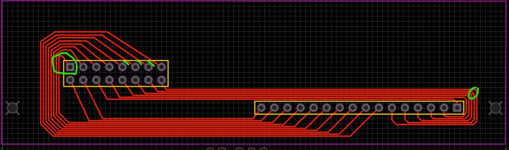
I can't say anything about whether the connections are correct, but here are some thoughts on the layout.

Watch the clearance. It should ideally be as large as possible; often I work with ~0.4mm trace width and 0.5mm spacing (1mm trace-to-trace). Take particular care around unmasked copper such as through-hole pads (e.g. on the 2x8)
Circled upper-left: the corner can be avoided by routing from the left/bottom left of the pad.
Circles right: angles a bit messed. Neatest is to use 45° angles for everything.
-
1
-
-
@Altitude had a similar idea:
http://midibox.org/forums/topic/20525-16pin-sil-to-16pin-dil-adapter/
Check that the fit works in a MB-6582, but I guess so?
MBBLM schematics and PCB discussions
in MIDIbox BLM
Posted
Inrush current issue? Though the LEDs seem to be driven with 1k, so not terribly high. Grounding issue between power supplies? Check all 0V are common. SRIO integrity? Try buffering the J8/9 signal and/or terminating the chain with an RC shunt.