

latigid on
-
Posts
2,524 -
Joined
-
Last visited
-
Days Won
149
Content Type
Profiles
Forums
Blogs
Gallery
Posts posted by latigid on
-
-
Hi Niels,
The power situation is fairly complex and there could be more than one source of noise. Some setups have no issues, some do. With MIDI obviously we have optoisolation so things are different there.
The power distribution in the SEQ could be better e.g. by improving the return current path (certain Molex connectors on the lemec boards/USB PCB are meant for this). I think that the LED matrices introduce some digital noise as they switch. I'm not sure if this the source of your noise or whether it is the more commonly observed phenomenon encountered when connecting USB audio devices. Could be that your USB +5V from the computer is not designed for the current that you draw from it or is inherently noisy. Peter tested a laptop and USB power bank, which were both quieter than even a phone charger, but a PC tower had a much noisier +5V line. He could filter out some of that noise but it was still worse than the laptop. His Eurorack PSU is transformer based with linear regulators and uses a copper bussboard. I would consider this system superior to a switching PSU and a flying busboard.
I would tend towards the powered USB hub like TK. uses for the SEQ. Another user still had issues with their hub but then one might imagine that that PSU was also noisy. Very hard to guess. There are also solutions to galvanically isolate USB and could be worth a try? Some are quite cheap and some much more expensive. I can't guarantee anything though, so it might be throwing money at the problem without a satisfactory result.
For the Euroceiver ground lift, the RS-485 standard recommends to keep the 0V reference connected, even though the power supplies on either end could be mutually floating. Imagine an extreme case where you have a long signal cable and a device either end. You have a massive antenna and a real "ground loop" if the power supplies are connected. In our case, we can have two different power supplies and we keep the signalling within the common-mode range by referencing to a common potential (0V). Without J0 jumpered, the signals may become more susceptible to data corruption as the differential voltages drift apart. You might notice that the setup works in your studio but not at a gig for example.
Instead of leaving J0 unjumpered you could try to connect a low-value resistor (say 10R) of suitable power rating across it. This might attenuate the noise that you hear.
Best regards,
Andy-
 1
1
-
-
@TK. cool!
21 hours ago, Elektruck said:Hi Thorsten,
Thanx very much for the fast reply, I'm sorry I'm not that fast.... But I think the Hz/V calibration works like it should now, although you really need a unipolar CV output. And I didn't notice any difference in the calibration procedure but maybe you just changed the code and not the procedure?!.... The renaming (Aout > CV 1t/m4) and the GP7 uni/bi polardisplay button is indeed more convenient and looking good!
I didn't remove the resistors yet, but I measured the following after the Hz/V calibration:
C2 on the sequencer gave me -1V, E2=0V, C3=3V, E3=5V . If I add 5 volt to this (changing from bipolar to unipolar) C2=4V, E2=5V and C4=8V and that's is exactly what it should be so that's why I think the calibration is correct. It is so confusing cause the CV input range of the ms20 is from 0 to 8 Volts, so the ms20 starts playing on E2/0V, and the highest reachable note in bipolar mode is only 1 octave higher E3/5V, and within this octave the ms20 jumps through 4 octaves. That's the difference between lineair and exponential, I was never good at this stuff, I hope you people understand me...
Thanks again for all the help and the new release, looks very promissing, 4 CV modules is superb and track labeling and all other stuff is just great.
When removing the offset resistors, consider that the LEDs on the octal PCB will be driven by a higher voltage (current). So consider at a minimum doubling the LED resistor values or even swap the LEDs on unipolar channels to different colour (with appropriate resistors).
-
I think you're doing great! :)
MB_NG is very flexible and comprehensive and you just need to know where to look. I have used it mostly to prototype/test designs for other systems and have never built a controller based on it. I would also say that I (still) don't fully understand the syntax and just muddle my way through the examples. That said, the manual chapter that I linked should serve as a complete documentation source for you. I think your blog-posting style is fine if it serves as a waypoint, no problem! I hope that you don't expect me to answer all of your questions though, because I think that it is your job to learn as you go, and probably the easiest way is just to experiment with the hardware. This is my experience anyway; because I did not write and do not understand the code structures, I need to apply them in hardware and learn by doing. So if you change this parameter you will get that result, which translates something abstract (unintelligible code structures) into something tangible (LCD messages with the desired padding and string format).
Still, if I can point you in the right direction I will (and anyone else should also feel free to do so!).
Chin up! All good!
Andy -
7 hours ago, ssp said:
I have been working on my layout for my 3 digit 7 segment displays i have ordered.
The values shown by my plugin are not the usual 0-127, what i need are.
if you move the pot all the way to the left its max value is -99
if you move the pot to the far right max value is 99
with the centre value being 0, or in this case just the centre line of the mide segment digit 2
this picture hopefully explains it better.
This is >128 values though, so you will need to use NRPN.
7 hours ago, ssp said:I am trying to get to grips with the matrix information, i understand the connection pdf on the dout boards as i have used them before.
I am also stuck on this section here:
DOUT_MATRIX n=1 rows=8 sr_dout_r1=1 inverted_row=0 mirrored_row=0 sr_dout_sel1=2 inverted_sel=0
DOUT_MATRIX n=2 rows=8 sr_dout_r1=3 inverted_row=0 mirrored_row=0 sr_dout_sel1=4 inverted_sel=0dout_matrix n=1 (this is the first matrix/sr) rows=8 (are the first 8 pins?), sr_dout_r1=1 (this is shift register 1) the common cathode is on the next section so this is shown is sr_dout_sel1=2 if i am correct.
i dont understand the syntax in this though, can someone explain it for me and i can then carry on writing the rest of the code
thanks
Again uCapps.de has all of the syntax explained:
QuoteDOUT_MATRIX
The DOUT_MATRIX command configures LED matrices which are connected between multiple DOUT shift registers.
Usecases:
-
Already with 2 DOUT shift registers it's possible to control 64 LEDs. One DOUT is used to select the column, the second DOUT to set the row pattern. By using the led_emu_id_offset parameter they behave like common EVENT_LED elements and can be controlled individually. This saves some hardware! (only 2 DOUT shift registers instead of 8 to drive 64 LEDs).
Other useful hardware configurations: with 1 DOUT assigned to the column, and two assigned to the row, up to 128 LEDs can be controlled from 3 DOUT shift registers. With two DOUTs assigned to the column, and two assigned to the row, up to 256 LEDs can be controlled from 4 DOUT shift registers. - Actually each matrix provides three separate "row layers", called r, g, b (red, green, blue). You get the message: this allows you to control multicolour LEDs!
- LED Rings and Meters - see also the LED_MATRIX_PATTERN configuration below. The led_matrix_pattern can be passed from a control element (e.g. EVENT_ENC) to the LED matrix in order to output a pattern based on the event value.
- LED Digits (7-segment displays) are controlled from a DOUT_MATRIX as well. Here are some interconnection diagrams with the appr. .NGC configuration examples:
Available configuration parameters:
DOUT_MATRIX Parameter Description n=<1..8> Specifies the matrix number which should be configured; it can range from 1..8 rows=<4|8|16> Sets the number of rows which should be scanned: -
rows=4: 4 selection pulses are output by the DOUT register specified with sr_dout_sel1. The pulses are available twice: at D7:D4 and D3:D0.
This configuration allows to scan up to 4x8 LEDs with two DOUTs, or 4x16 LEDs with three DOUTs. -
rows=8: 8 selection pulses are output by the DOUT register specified with sr_dout_sel1. The pulses are available at D7:D0
This configuration allows to scan up to 8x8 LED with two DOUTs, or 8x16 LEDs with three DOUTs. -
rows=16: 16 selection pulses are output by the DOUT registers specified with sr_dout_sel1 and sr_dout_sel2. The pulses are available at D7:D0 of each register.
This configuration allows to scan up to 16x8 LEDs with three DOUTs, or 16x16 LEDs with four DOUTs.
inverted=<1|0> DOUT selection lines will be inverted with inverted=1. This is required if the LEDs of the matrix have been connected in the opposite order: - inverted=0: Cathodes are connected to the DOUT selection lines, see also this schematic.
- inverted=1: Inverting sink drivers have been added to the DOUT register.
- inverted_sel=1 and inverted_row=1: Anodes are connected to the DOUT selection lines (swapped polarity)
inverted_row=<1|0> DOUT row patterns can be inverted with inverted_row=1 sr_dout_sel1=<0..16> Sets the first DOUT shift register which should output the row selection signals. sr_dout_sel2=<0..16> Sets the second DOUT shift register which should output the row selection signals in a row=16 setup.
Set this parameter to 0 if a second DOUT is not required.sr_dout_r1=<0..16> Sets the first DOUT shift register of the LED matrix row. sr_dout_r2=<0..16> Sets the (optional) second DOUT shift register of the LED matrix row. sr_dout_g1=<0..16>
sr_dout_g2=<0..16>These parameters allow to drive duo-colour or RGB LEDs by using a second set of DOUTs connected to the green LEDs. sr_dout_b1=<0..16>
sr_dout_b2=<0..16>These parameters allow to drive RGB LEDs by using a third set of DOUTs connected to the blue LEDs. mirrored_row=<1|0> The pins of the DOUT rows can be mirrored. This happens only for the shift register value itself. Means: if two DOUT shift registers are assigned to the row, they won't be swapped. If this is desired, just change the sr_dout_r1/sr_dout_r2 assignments. led_emu_id_offset=<1..4095> With a value >0, the LED matrix will listen on EVENT_LED events instead of EVENT_LED_MATRIX, starting with the specified ID. A matrix of 8x8 LED can emulate 64 LEDs with individual event assignments this way.
In order to avoid conflicts with LEDs which are directly connected to DOUT pins (and which are accessed with LED:1 .. LED:256), it's recommended specify emulated ids outside this range, e.g. led_emu_id_offset=1001.lc_meter_port=<USB1..USB4|IN1..IN4> Special option for the Logic/Mackie Control emulation. It allows to transfer incoming Poly Preasure events (which are used by the protocol to trigger the meters) to LED bars. An usage example can be found in following template (search for "meter"): logictrl.ngc Please note that all assigned shift registers can't be used for other purposes anymore! E.g. if only 4 rows are scanned, and accordingly only 4 pins are used to select the columns, the remaining 4 pins of the shift register can't be used to control 4 LEDs directly!
-
Already with 2 DOUT shift registers it's possible to control 64 LEDs. One DOUT is used to select the column, the second DOUT to set the row pattern. By using the led_emu_id_offset parameter they behave like common EVENT_LED elements and can be controlled individually. This saves some hardware! (only 2 DOUT shift registers instead of 8 to drive 64 LEDs).
-
This is no longer Liquid Crystal but segment displays :)
QuoteDOUT_MATRIX
The DOUT_MATRIX command configures LED matrices which are connected between multiple DOUT shift registers.
Usecases:
-
Already with 2 DOUT shift registers it's possible to control 64 LEDs. One DOUT is used to select the column, the second DOUT to set the row pattern. By using the led_emu_id_offset parameter they behave like common EVENT_LED elements and can be controlled individually. This saves some hardware! (only 2 DOUT shift registers instead of 8 to drive 64 LEDs).
Other useful hardware configurations: with 1 DOUT assigned to the column, and two assigned to the row, up to 128 LEDs can be controlled from 3 DOUT shift registers. With two DOUTs assigned to the column, and two assigned to the row, up to 256 LEDs can be controlled from 4 DOUT shift registers. - Actually each matrix provides three separate "row layers", called r, g, b (red, green, blue). You get the message: this allows you to control multicolour LEDs!
- LED Rings and Meters - see also the LED_MATRIX_PATTERN configuration below. The led_matrix_pattern can be passed from a control element (e.g. EVENT_ENC) to the LED matrix in order to output a pattern based on the event value.
- LED Digits (7-segment displays) are controlled from a DOUT_MATRIX as well. Here are some interconnection diagrams with the appr. .NGC configuration examples:
-
Already with 2 DOUT shift registers it's possible to control 64 LEDs. One DOUT is used to select the column, the second DOUT to set the row pattern. By using the led_emu_id_offset parameter they behave like common EVENT_LED elements and can be controlled individually. This saves some hardware! (only 2 DOUT shift registers instead of 8 to drive 64 LEDs).
-
Consider an LED matrix with 7-segment displays.
-
Great work! The universal solution will be much appreciated as we have spare UARTs on the upcoming BLM :)
-
Good news, nice!

This also seemed to eliminate the issue for the other user. I think it still remains to connect up the modular and the computer at the same time...
Have fun, that looks like a really cool rig to use
 .
.
Happy jams in 2020!
Best;
Andy-
1
-
-
Thanks for the diagram! Just to preface, Eurorack is the Wild West of electronics. There are many ways you can put things together and some will give better results than others. The "fundamental flaw" in Eurorack is that the 0V line serves as both a reference and a current return path (i.e. an unbalanced system). If there are potential difference mismatches on the 0V lines, noise can result. So the idea is to have the 0V resistance as low as possible and to run power rails as much in a "star" configuration as possible.
Searching a bit on MuffWiggler, the Row Power seems to have some history of noise problems. It might be that this is not the ideal way to power your Eurorack though there are a few things to try/clarify.
-
Is the mains connector to the DC brick 2 or 3 pins on the brick end?
- With the power off and any voltages discharged (take care!), what is the resistance from the earth pin to the DC barrel?
-
Your MG rack has two Row Powers, correct?
- Are things actually connected like this on separate rows or more like the hand-drawn diagram?
- What happens when you disconnect the ES-9 USB?
-
Is it a desktop or laptop computer?
- If a laptop, what happens when it's running on battery?
- What is the power distribution in the case? Flying buss or bussboard?
-
Is the Euroceiver powered with the case +5V or the onboard Vreg?
- (I suppose the Vreg)
-
What happens if you power the Euroceiver with USB (check J5 jumper!) derived from the Mac while also powering the SEQ with USB?
- Better might be to use a powered hub to increase the available current.
- What happens if you power the SEQ from e.g. a phone USB charger rather than the Mac?
-
What happens if you remove the Euroceiver J0 jumper?
- Generally you do want to leave this connected, but disconnecting it will cut the 0V connection between the SEQ and Eurorack.
Cheers,
Andy -
Is the mains connector to the DC brick 2 or 3 pins on the brick end?
-
Hi Niels,
We heard of another similar issue. Could you explain exactly the wiring setup you use? It is important to know the power sources of everything (linear or switching PSUs, power banks, hubs), how they are plugged into the wall, whether you use a computer or laptop, the various jumper settings on the Euroceiver and so on.
Is it particular modules or everywhere that you notice the hum?
Best regards and Happy New Year!
Andy -
Nice to see your progress!
It's confusing, but there is a difference between "bootloader hold" and flashing the "bootloader hex app" through MIOS Studio.
Bootloader hold, using the blue DISCO button, is when you mess up a custom app or the flash is corrupted somehow and the Core will not boot anymore. This allows you to fix the Core with a known good hex upload.
Bootloader app is essentially the same but can be normally flashed with MIOS Studio. Upon USB re-enumeration you can then alter boot settings, including changing the LCD type.
-
Cheers! Have a good one!
-
What voltages do you read out of the output with 1/2/3/4/5 V... or min/mid/max?
Looking at the MS-20 manual, it seems to expect a linear 0-8V CV for the VCOs? So maybe normal V/Oct scaling is already good? If you really need to work within the positive range, remove the offset resistor on any channels you would like to use in unipolar mode. These resistors xR34,xR35,xR36x... etc. are listed in the BOM on the transmute8 page.
-
Right idea, just should be in parallel with the resistor rather than the cap.
-
The circuit is a power-on reset (POR) that charges the cap for short period until the power rail stabilises. If you omit this then the displays will probably show garbage pixels. Only one POR is required for all of the displays. I would also suggest to wire a 1N4148 diode in parallel with the resistor with the cathode band at the +3.3V node.
-
Cheers! Enjoy your new SEQ! If it's working well then you have #24!
-
2 hours ago, sis.tm said:
Hi,
on the ja board mine shows the gate of the track but i saw other movies showing track position and you say you can also show bpm. How exactly do you change the display of the ja board?
Cheers,
NielsHi Niels, it's there in the Utility -> Options menu.
Just now, Pivado said:Hi guys,
I have been (silently) following Midibox for years and some time ago I made the decision to build the Midiphy SEQv4 myself. Everything went pretty well (great video instructions!) until the very end where I put it together into the box and the left display would not show anything during and after booting. When I press some keys random characters will show up on the display. I have now stripped down everything to a bare minimum (Core, usb/sd, 2 x display) and the problem still exists. I have tried swapping the display cables on the Core, if I do this the problem moves to the other display, this should rule out a problem with the display or the flatcable. I have attached a picture of what I see after booting.
I hope there is someone here who could give me a hint on where I should start looking to solve the problem.
Thanks,
Pieter
Hi Pieter,
You can try this thread for troubleshooting if you wish:
http://midibox.org/forums/topic/20993-troubleshooting-midiphy-seq-v4/?page=1
The OLEDs are probably fine but I would still suspect the cable. A slightly crooked crimp can short two lines together.
Common issues with a display not working are:
- J15_S not jumpered to 3.3V
- R33D value (should be 560R)
- Cable strands shorted together
- Cable makes contact with components on the OLED PCB (isolate with kapton tape)
- Cold joints or shorts on wCore 2x25 pin headers (trace back to pin names or even MCU pins according to http://ucapps.de/mbhp/mbhp_core_stm32f4.pdf)
Best of luck!
-
1
-
You can try it! I've always entered the commands one at a time though.
-
If you have a READY. message, then it works :)
-
Bootloader is here:
http://ucapps.de/mios32/mios32_bootloader_v1_018.zipUpload as normal hex through MIOS Studio and change the LCD type + store as you note above.
Also check that the jumper is set to the correct voltage for your LCD and that the cable is correctly "mirrored" probably by soldering the pinheader onto the back of the display and connecting the IDC there.
Merry Xmas,
Andy -
Hi Hal,
Probably we/someone should write a wiki entry or something on the new features! The idea is something like this:
-
The encoders underneath the OLED displays work just as before
- The encoder switch functions are in theory freely assignable but are typically used to accelerate encoder data
- The first row of illuminated "Soft" keyswitches are equivalent to the GP buttons plus the dual-colour step LEDs of the Wilba version
-
The second "Selection Row" keyswitches change function depending on the button lit up around the datawheel on the JA board (see below)
- These LEDs are also dual colour
- The row of Apem/MEC switches should be familiar to V4 users
- The RGB Beat LED flashes a different colour for the beat and the whole measure
-
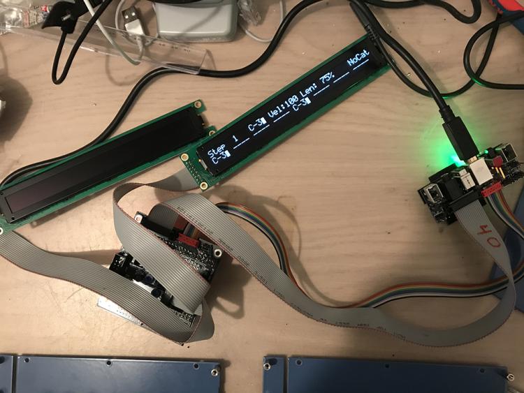
The JA board has a built-in Activity Matrix and typically displays the track position in a single colour
- Other display options like a custom logo or the current BPM can be displayed (both with optional beat flash; also for the TPD)
- The datawheel functions as before and has a push function (currently not assigned to anything I think)
- The JA board carries the transport controls (play, pause, stop etc.) and a few extras
-
The Selection Row buttons around the datawheel are:
- Step View
- Tracks
- Parameter Layer
- Trigger Layer
- (Drum) Instrument
- Track Mute
- Bookmark
- Song Phrase
-
On the JA board, press and release one of these to change the Selection Row function
- Press and hold the JA button to temporarily change the Row function, which jumps back to the previous function on release
-
On the v4+, all 16 Selection Row buttons are accessible and multiple selections are possible by holding down several buttons simultaneously
- Tracks are still colour-coded into groups of four tracks and named identically (e.g. G1T1-G4T4)
- On the V4, tracks were chosen with four track groups and four tracks for a total of 16 tracks and only three trigger and parameter layers had dedicated buttons (normally holding Param./Trig. C would bring up the layers menu screen)
-
Rear panel has a USB B port (power/data) for better mechanical strength
- Switch for USB OTG host is provided but we notice some devices are incompatible
- Footswitch/gate input (currently not assigned to functions)
-
Rear panel LEDs:
- Green: power
- Orange: SD Card available
- Red: any received MIDI IN
- Blue: LED any transmitted MIDI OUT
I think that's it!
Best,
Andy-
2
-
The encoders underneath the OLED displays work just as before
-
You mention AINSER, but talk about muxes. Do you mean AINSER64 (even if not all multiplexers are used)? Are you using a self-designed board or something from uCapps?
Maybe the scanning isn't working properly? Try http://ucapps.de/mios32/ainser_jitter_mon_v1_002.zip for diagnostics.
-
@Adam Schabtach, nice job and well done on #23! The subtle colour mixing is a great idea and exactly the sort of thing intended with the RJ/SJ setup.
Enjoy!
-
Isn't the transistor topology similar to a linear voltage regulator anyway?
You might avoid the issue in the first place by starting with a more reliable power supply. Users here often also employ a crowbar circuit, so those might give you some possible ideas or directions.
For your simulation, consider that the transistors should be properly specced to handle the current loads, also real components might have tolerances or voltage drops that push your limits.

understanding the .ngc code
in MIDIbox NG
Posted
Just use MIOS Studio and assign one of the sliders to your CC event, or rather assign your event to one of the sliders.
You can probably use J10 or J5 as analogue inputs.