JMS
-
Posts
100 -
Joined
-
Last visited
Content Type
Profiles
Forums
Blogs
Gallery
Everything posted by JMS
-
Dance and video... uh there's music in it, it's kinda ontopic...
JMS replied to stryd_one's topic in Miscellaneous
cimo was right on with his post.. but this is what i used to get my experiments going... -- cheap-a$$ dumspter dive find webcam pointed at the top of my desk from the ceiling -- reactivision -- printed the fiducials on paper and taped them to the top of c batteries. -- Pure Data - with gem libraries installed -- write your own patches for PD... maybe start with the "OSC Recieve" example patches... i couldn't find any ready made patches when i was messing around with it, there may be some and better softwares to do it with nowadays. Since then i had a serious HD crash and lost my patches before i could get them all up on the PureData wiki. it was nothing hardcore though about programming it.. just a lot of steps and if you don't have a second computer to do the audio generation then you may experience some hardcore lagging. performance with the cheapo webcam is not so good, best framerate you can get is 30 fps (or 29.97) ;) -
i got them on watch, the autction has still got like 9 days on it. (the end price may end up more than $79.00 +$19.00 shipping, depending on who all bids on them.) if someone overseas wants to bid and win it... you can use me for a shipping post in the states. i'll email my shipping address if needed.
-
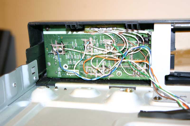
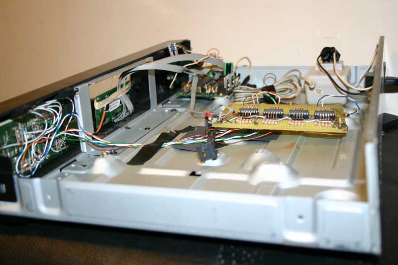
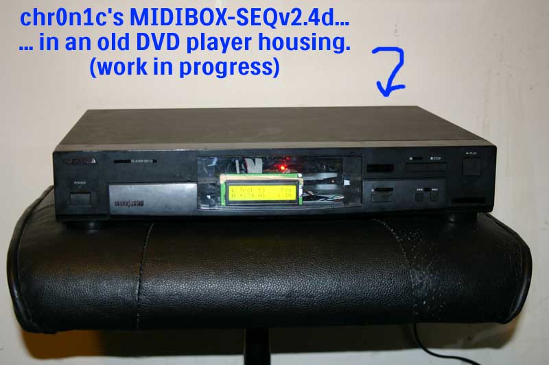
yo! i'm in the process of putting together a mbseq v2.4d-vintage (since i only had a 2x16 lcd) to run this sampler i just bought without my computer crashing in the middle of a song... Question: can i change the values of all steps independently with only 1 pot or do i need like 16 (or 64) of them? or should i be looking into the data wheel/encoder route for this? or is none of this even possible with a 2.4d seq and i should just break down and buy 2 2x40 lcds and build the v3 seq? the deal is i have it all mounted inside a stripped out dvd player case and there is not room here for 64 pots, so, i was hoping i could change all note/length/gate values with only one pot. i can fit all the buttons needed on the front... i already planned that out. below is a few shots of the progress so far... one shot of the front, one shot of how i re-used the already in place front switches/buttons and one view of the inside as of a few days ago... it's already in a much nicer state than the pictures show as i've done a bit of work on it since, so don't laugh too much at it... (it's a work in progress) EDIT: the PLAY and STOP buttons do what they are labled to do... the fast forward and rewind buttons move through the menus... pause is the menu button, open/close is the button to switch what i am editing in the menus. i still need to mount the 16 GP buttons and the rest... (above and around the lcd maybe)
-
paypal me some monies + forwarding shipping costs and i can send them overseas, i ship antique car parts all over the world daily... just sent some 1959 ford reproduction rocker moldings to new zeland and a set of 58 ford washboard trim panels to australia today! (holy cow it costs a lot to send 80 inch long rocker moldings fedex to new zeland!) on a side note.. i just bought a cherry c64 with a 6581 from ebay last week and i just got it home today from the shop, ran a sid test with basic and it seems to be making the right noises. (w00t!) (ps... i only paid like $14 US for it, INCLUDING SHIPPING!) guess who's going to be building a midibox-sid soon... http://cgi.ebay.com/ws/eBayISAPI.dll?ViewItem&ssPageName=STRK:MEWNX:IT&item=380103735568
-
yeah, i tried putting the url in the tags, i dunno why it wouldn't work.. i did it before, lol! thank you SLP
-
i built my own mini 3 axis cnc mill/engraver before i found midibox and i actually cut my own core board... that was about 2 years ago and i got to drilling the holes to mount parts and decided to just buy a ready made core board from the shop to complete my first project, so i can't tell you how it all worked out yet... it was a fun process though! -- you can convert board files with eagle and pcbgcode to the cnc programs needed to run the machine and cut or drill boards for you -- it's messy (way more messy than some etching chemicals) -- building a machine capable of the precision needed for some of these small traces is a serious challenge! here is a video of the core board being cut on my machine for an example: http://www.youtube.com/watch?v=kl0guIkizVQ if you need any help along the way of the cnc route i'll add my two cents! -- chr0n1c EDIT: if someone wants to fix this embeded video, go ahead, i tried to make it work, ha! Edit: fixed! Edit: no it's not... I can't find any such video... just find the vid, and when you're viewing it in your browser, copy the URL from your address bar, and paste it between the youtube tags.
-
Dance and video... uh there's music in it, it's kinda ontopic...
JMS replied to stryd_one's topic in Miscellaneous
that kinda stuff should be pretty easy to throw together with Pure Data or any of the like programs... i myself experimented with a reactable setup.. but i never had a decent projector. BUT! i just recently found a PERFECTLY WORKING!! sony vph-1252 RGB projector sitting out by the trash in front of someones house down the road! of course i dragged it home and set it up! which means i gotta start playing with the reactable stuff again ;) -
old pentium/cyrix motherboards ;)
-
Australia - Anyone had experience with labels / overlays etc
JMS replied to Futureman's topic in Parts Questions
i was going to suggest to print it out on the clear inkjet labels, then just put another plain clear label on top of it for some protection... easy to redo if you make a mistake or wanna change the keyboard layout. -
ehh.. ok fixed... i finally tried to recompile and it's all well after setting ALL the correct environment variables... in /etc/environment. (i swear i read about 30 forum posts and wiki pages looking for them.. :D ) thanks again!
-
yes, did this as a first step... DOH! this is one would have prevented me needing to change the "declare -a" to "local", i bet... with stryd's help in chat the other day, i discovered what was missing... it was my PATH variables. i did set the MIOSPATH and MIOS_BIN_PATH up in my /etc/environment file. i must have missed the SHELL variable in my excitement of learning to program these pic thingys. (on a side note... the ubuntu build environment howto has "and now we need to set up our environment variables..." and then nothing after searching through the wiki and the forums i didn't find a list of everything that needs to be set with PATH=. maybe i overlooked something) will give it a go with a clean copy of mios-gpasm, after i set up the rest of my PATH (MIOS_SHELL="/bin/bash"). thanks for the input!
-
here's my version of a DINX4 on protoboard :o i built it last night in about 3 hours... ... still need to mount the rest of the input terminals, but you can get the idea, right? IMG_4692.JPG IMG_4694.JPG IMG_4692.JPG IMG_4694.JPG
-
so i was getting ready to try and start making some kinda app... i figured the best place to start would be to get this to compile on my box first. along the way i ran into two errors when i run make in a clean copy of the sdcc_skeleton from svn. 1. the easy one... /home/l/midibox/svn/mios/trunk/bin/mios-gpasm: 24: declare: not found /home/l/midibox/svn/mios/trunk/bin/mios-gpasm: 27: declare: not found i fixed these 2 errors by changing "declare -a" to "local" on both lines in the mios-gpasm script and saving the file. ---apparently this error is caused by the ubuntu team switching the default shell between 6.06 and 8.04 from sh to dash according to what i read here: https://wiki.kubuntu.org/DashAsBinSh 2. here is where i got stuck: sh /home/l/midibox/svn/mios/trunk/bin/mios-gpasm -c -p p18f452 -I./src -I /home/l/midibox/svn/mios/trunk/include/asm -I /home/l/midibox/svn/mios/trunk/include/share -I /home/l/midibox/svn/mios/trunk/modules/debug_msg -I /home/l/midibox/svn/mios/trunk/modules/app_lcd/dummy -DDEBUG_MODE=0 -DSTACK_HEAD=0x37f -DSTACK_IRQ_HEAD=0x33f -I /home/l/midibox/svn/mios/trunk/modules/mios_wrapper /home/l/midibox/svn/mios/trunk/modules/mios_wrapper/mios_wrapper.asm -o _output/mios_wrapper.o /home/l/midibox/svn/mios/trunk/bin/mios-gpasm: 37: Syntax error: "(" unexpected (expecting "fi") so i'm sorta new to programming.. does anyone have any ideas on what would fix this in the mios-gpasm script? obviously i know it's a syntax error in the code on line 37, but, i don't know what the correct syntax is YET.. i will search on! in the meantime... does anyone have any ideas on what would fix this in the mios-gpasm script?
-
i know you mentioned that you'd like to build it all yourself, but, i just used a pickit2 (i think it was like $35 US or something) and it works great.
-
Mouser Part #: 763-NHD-0216PZ-FLYBW Manufacturer Part #: NHD-0216PZ-FL-YBW Manufacturer: Newhaven Display Description: LCD Character Displays 2 x 16 STN-Y/G 80.0 x 36.0 2.4504ms i know it's an old topic but i was playing around...
-
I started this wiki page, if anyone has any edits, additions or better info feel free to insert it! This process worked for me, so it should work for others. For now it's under the tools section, wasn't sure where it should be.. but I think it should at least be there somewhere! Pickit2 - Programming the core bootloader with a pickit2. WIKI LINK: http://www.midibox.org/dokuwiki/doku.php?id=pickit2
-
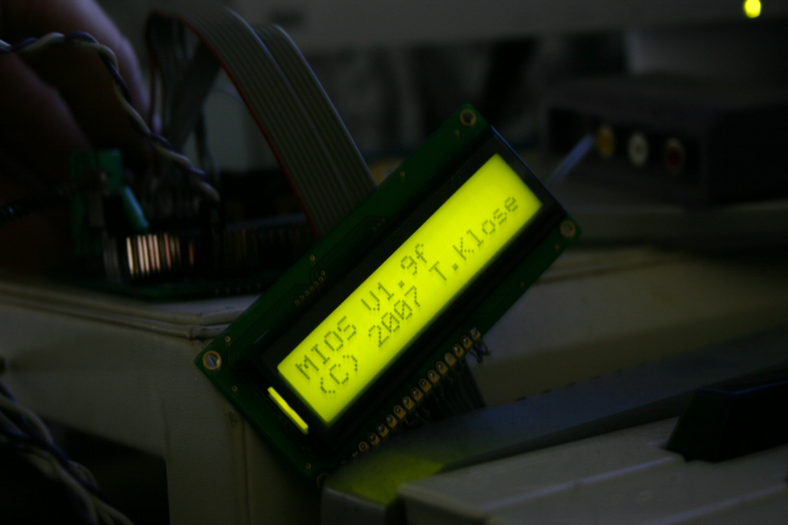
so, my core is finally working! wow, it's been a while since i started this project. i decided to order a pre-made PCB from smash and screw with my DIY pcb for the second box. i wasn't sure how mine would hold up in the long run... i did buy enough for a second core when i ordered everything so i'll test this board out soon enough. the first core i built turned into a midimon for now, sprawled out across my desk. it's sitting in between my keyboard and FL Studio for now so i can see what notes are going into the computer. (i'm still teaching myself chords and junk.) i can also send midi notes out from tracks in FL Studio to see what's playing. Right now i only have a 16x2 LCD hooked to it, can i use the two lcd screen trick on this midimon and have the data scroll across both screens? do i need to change anything in the code and recompile to make this work? hopefully just a simple config? and using the second enable pin? (i need to do some more reading.) here is a link to a photo gallery of the build process: http://ohiopctech.com/cpg/thumbnails.php?album=19 thanks for all the help to all the forum members who post clear and precise info! special thanks to TK, for putting this project together!
-
Share your early (not-so-great) works! (formerly your first one)
JMS replied to Enth's topic in Songs & Sounds
nice to hear some tracks from everyone... i've just in the last few years become interested in making music, though i've always enjoyed making lots of noise. here is an early track i put together using fruity loops, reason and cool edit... just trying to figure everything out. love it or hate it, it's here! ;) TheMostDopePSA (August 27, 2007) - http://www.archive.org/details/TheMostDopePSA -
Me being (sorta) new to the whole pic programming thing... i get confused easy with all the terminology. seems as though my programmer will do either mode and the pic i am using was programmed in HVP with the adapter i made as long as the jumper in my schematic above is connected. stryd_one, thanks for pointing out my mistake in the post. short story, you can use a pickit 2 and my adapter to program a pic for midibox.
-
once the bootloader code is burnt on the chip.. it disables the pin 38 for lvp use via a config bit. unless i am completely missing something here... this process works. asking because i am curious, not to be rude... how could it brick a chip?
-
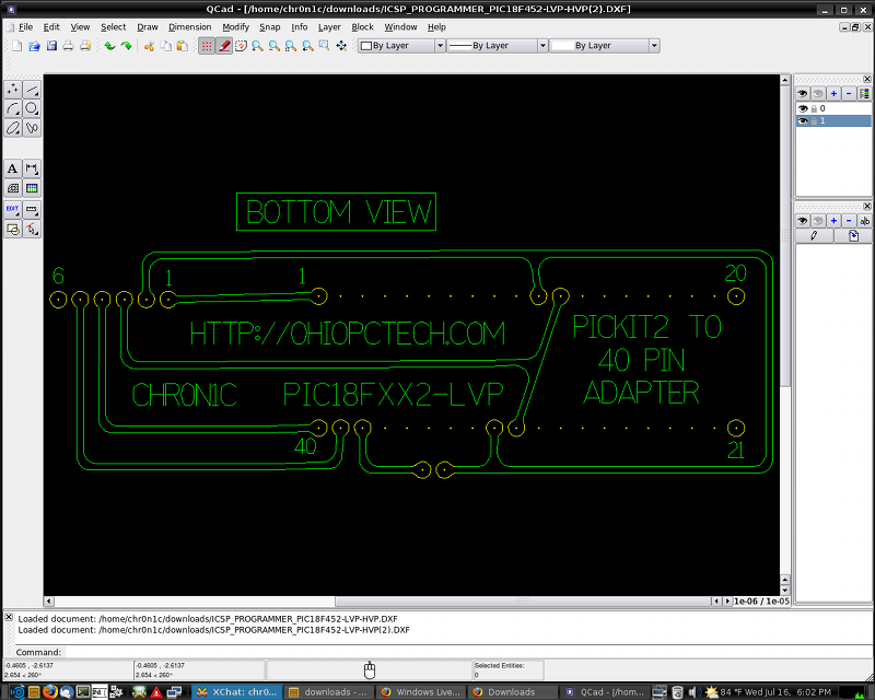
pickit2 confirmed working with my midiboxen pics... by me, earlier today... EDIT(EDIT): the pic was burnt in HVP mode on a DIY icsp adapter with the pic out of the midibox core... LCD works... i've got a ready message waiting for me to pick an app to upload from mios. i burnt the bootloader with the pickit2, stuck the pic in the core and plugged it into the output of my radium 49 usb/midi keyboard and sent the mios blindly with no midi input from the core. i did crank up the delay a few ms though just to be safe. picture of my schematic for the DIY icsp programming adapter is attached below. it uses an ic socket, a 6 pin header and 5 short lengths of stripped out cat5 cable... the schematic would be looking at the board from the bottom (single sided etched pcb) (short the jumper on pin 38 to make it work right) EDIT: scale the layout so the pins are 0.100" apart if you are going to etch it!
-
FUNCTION GENERATOR: (and other DIY nifty projects) http://www.nuxie1.com/guides/fungen-v2-kit.html i started building this a while back, i even have the g-code to cnc out a board backed up somewhere. i cncd out a prototype board, drilled all the holse, soldered in the socket for the xr2206. i ordered some xr2206 samples... i never did much with the rest of the project except look at it sitting on my bench half done. i think it would be a DOPE! sound generator if attached to the midibox and a small app written, which could display the the waveforms maybe even? here is a link to the post with a video of the code being tested on my mini mill and a pic or two... http://ohiopctech.com/dp/?q=node/136 (sorta) OFFTOPIC: just got my mbhp_core running with an lcd today, ready message on the lcd about an hour ago! so i'll be building some kinda function generator soon to be interfaced with this core. (and teaching myself asm in the process so i can try to code the app for it.)
-
i was wondering while i am sitting here waiting for my max232 chips to be shipped... is there something common as far as computer hardware is concerned that i could re-use a max232 chip from? there is all kinds of electro-junk sitting around here but i can't begin to imagine what this chip would be in. thanks ahead of time for any awesome ideas you all come up with. :D
-
ty, nils, will have a look!
-
anyone know where to get the code for this app? i tried the links and browsed the wiki and didn't see it... these links are dead :( ... and i almost got my core finished... just gotta program the pic! (and find an lcd) w00t!