

ssp
-
Posts
659 -
Joined
-
Last visited
-
Days Won
4
Content Type
Profiles
Forums
Blogs
Gallery
Posts posted by ssp
-
-
take a picture of the board, open it in paint, then label the pins you need the info about, send an email to useaudio again attach the picture, ask them for the details of each pin assignment/rating details of in and out functions per pin. if you send them a picture they may be more likely to help, simply because they can see you actually own a board in the first place.
they are the best people to let you know what each pin's assignment is.
-
well.
when im designing a case i start with a 2.54 mm grid, i then get the tech drawings/data sheets for every component im going to use and start from there, this is done on a 1:1 scale so fitment checks are exact.
so i get a sheet of vero or padboard, get my encoders and buttons and place them onto the board, i then take the centre of each component and measure the distance between centres. once i have the measurement between each centre i then use my cad software and enter the hole dimenstions needed into that for the faceplace.
using the padboard i then mount all components and make sure i have space for some 3mm holes to be drilled in the corners of the board and if needed a centre hole for support. with the cad software i would then print a 1:1 scale print of the faceplate and then cut the holes out, take the pcb with parts mounted and test fit, i find printing onto a good stiff paper say a 230gsm is a better option.
with this done i then look at adding headers to the padboard and linking the cables from the components to the headers.
as for mounting, well with the 4 holes , one in each corner of the padboard you can then get your faceplate material, for example say its some aluminium sheet, get some adhesive backed printable paper, print the hole layout for the face onto that at 1:1 scale. make sure your holes etc have got the centrepoints marked.
use a centre punch and put a small puch mark in the centre points of each hole, get a drill bit for the hole, if you can get a slightly larger one thats better, so for instance if the part dimension is 3mm then get a 3.5mm this allows for tolerance. drill the holes.
you would also have the 4 holes for the pcb mounts as well, you can countersink the face panel holes and use csk bolts 3mm this then leaves the heads flush with your face, or if you dont want this then use some dome head 3mm bolts.
so you put the bolts through the front of the faceplate, then on the rear you can fix a 3mm nut and to keep it in place a little dab of threadlock.
should you need a spacer put it over the bolt thread then slide your pcb/padboard onto the back of the faceplate and then use 4 more nuts on the back of the pcb to fix in place.
i will upload some pics later on showing this method to explain it better.
i hope this helps in some way.
-
if you look at the mackie c4 or the behringer bcr2000 you have multiple encoders, so if you take them top to bottm as a strip, then it becomes easy to do.
so if you had a grid of 8x8 encoders, the first line of 8 top to bottom are strip one and the next strip two and so on. then you can assign different functions to different groups, you just select the group function for what you want it to do. take a look at the tutorial page on ucapps http://ucapps.de/midibox64e_tutorial.html scroll down to morphing.
the 64e is a bloody amazing little control unit and the built in menu is so easy to use, combine it tiwht the editor and it makes things so easy.
as for the casework , yes i can help you with that, but we need measurements for positioning etc, its not difficult to do, but you need an origin point or datum point for reference, this is where all measurements are taken from. once you have a fixed point you measure the centre points to each button, encoder and fader etc, this then allows a quick face panel to be drawn with all the necessary tolerances for buttons and encoder shafts to poke through after paint or powdercoating.
prehaps a little tutorial would be in order regarding casework and how to layout and take tolerances into account.
if you need more help let me know
-
once again if the harrison allows you to assign controllers to the on screen controls for automation then yes you can, make sure each control on the hardware has its own cc#, if you duplicate it on another control then each one will make the same on screen control move.
and one really important thing... wheres the damn pictures!! lol
now come on, no excuses or slacking, you have to put some pictures up for us to see your work ;)
-
go here, read up: http://ucapps.de/midibox_lc.html
-
using a ruler isnt really the best idea and the drawing does show tolerances of o/u (over or under) dimension size. on the back of your lcd you will have the exact model number of the lcd, check its the right one for the data sheet, if not, google the model number and you will find the data sheet.
look on ebay and buy yourself a nice set of calipers, i have digital and dial calipers. they dont cost much anymore.
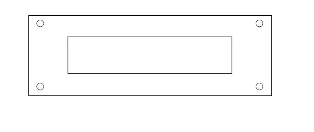
also here is an idea, there are some free cad programs on the net, grab one, draw the data sheet data to the cad software, now you dont need everything, you want the outer dimension, the 4 holes and the centre cutout rectangle, then print it on stiff paper say a 210gsm paper and cut it out with a sharp scalpel or craft knife, then put it on the lcd, that way you can check it on a 1:1 scale, this way you can check the placement of the holes to the screen centre etc.
like this

-
look smashy send kits out every day all over the owrld and i can tell you as has bassman, he bloody works hard to do so.
you gotta remember the kits leave smashy, hit the usmail depot, then hit the airport, then are handled there and sorted, then sent over by air mail, then they hit uk customs, who as we all know like to take thier own sweet ass time processing and notifying parcel force, parcel force collect the goods, then they hit your local depot, but they dont get delivered because they send you a letter that takes 3 days to arrive to tell you you have duty to pay on the delivery and until you pay you cant have them, so then you either pay on the phone ( which i do) or you goto the depot pay and collect.
personally i place my order, it gets sent express and its got online tracking which smashy always makes sure is there. and i wait for it to hit the uk, and then it gets a parcel force tracking number, in the uk the usps number gets changed to our uk tracking system numbers. and then it tells me via email its at the depot.
never had an issue with smashy parcels never will, a little patience goes a long way.
-
ok well i have had a busy few days.
i was able to finish the graphics for the front panel in illustrator and print them to lazertrans, i left them cure overnight. then i cut them to shape and soaked then applied to the casework.
here you can see the transfers just after application, the milky white is where they are dry, the clear is water left to dry off.

heres the case drying off after a coat or so of laquer, the laquer has made the transfer go completely clear, after this has dried i will then rub it back with some fine wet and dry and then use some compound to polish it up a bit.

heres the case re-assembled and finished (almost) i just have to wrap the side cheeks in the vynil and put the gfx on the buttons, apart from that its finished.


im quite pleased with how its turned out, however i think silkscreen would have been better than the lazertran, but then it would have cost almost £200 to have had that done and i really wanted to try the lazertran out.
in use the controller is great, the software responds to it extremly well and its mapped to all the features now.
i plan on making an expander for it that will have extra controls, encoders, faders buttons etc that can be mapped, so im working on that at the moment as well as the design for the console for the next build.
i really need to thank nils for all his help with this, he was able to suggest a workaround for the fsr sensors and also cleaned up my really bad eagle efforts and arranged getting the boards made in china. also the guys in the chatroom who i bugged non stop checking and re-checking things and making sure i was getting certain bits of code right. thanks to thorsten for the amazing thing that is midibox and mios without which this project would not have happened and also for all his help recently with me learning meta events. also thanks to wilba for sending me the encoders and the lcd displays i needed for this all the way from australia.
im looking forward to the next build eagerly!
ssp
-
nice project artesia!
i have an old scanner here , so i may as well give that a go! i did find a pdf project on the elektor site i grabbed using one of the old plastic tool trays. but this looks much better.
i will try this next week , just grabbing some leds off ebay now and some other bits.
-
sorry phil i didnt think to say to speak with you, maybe because im having the mother of all brain farts this week!
-
i found this thread earlier
would this do what i want? and how would i implelent it into my current setting
dout sr1 pins 1-8 are assigned to dinx4 sr8 button 54-64
-
your in luck then!!!!
what you need to do is come into the chat and speak with smashtv, he is a lighting tech and can help you out on a lighting controller better than anyone i dare say.
ok easiest way is this, goto http://mibbit.com/chat/ then do a channel search for midibox, when you find it click on the name and in your browser a chat window will pop up, you will see most of us lurkers in there, change the name it gives you to something else by typing /nick bob or what every you want to call yourself. smashtv is in the chat most days and he will be able to advise you.
-
i have tried several things to solve this issue now and i still cannot get the lights to stay on until the next button press.
-
i solved the initial issue earlier today and now the leds i need to light up, light up. however unless the button is in toggle mode the buttons do not stay on.
what i need is for a button which is not a toggle to have its light stay on until another button is pressed and then the new led comes on and the old led switches off. is this possible? and how
thanks
-
i wouldnt bank on then even existing protosx, 1st and only post and its to sell something, then followed up by a single post first post from someone looking to buy them. prehaps im wrong but it stinks of all not being what it seems.
always be weary of sales like this, people will try to con you anyway they can these days, but hey prehaps the original poster will prove me wrong?
-
industry standards here, i use: AKG K 141 mk1 originals, beautiful headphones to listen on and then for an all rounder with years of use from everyone its the Beyer Dynamic DT100 headphones, i use them when i am writing.
-
your in luck i haz found you a helperz!

-
been tweaking a few things, and checked the side panels. i have to wait for the vinyl to arrive to cover the panels. the graphics are ready to apply, plan is to do them this week then apply the laquer as soon as possible afterwards.
using the controller with the software, makes things so much easier now.

checking the fitment of the side panels.

-
look i have made it easy for you to understand, i cant be any simpler, if you look at the cnx description which you did, goto ucapps.de, look at the info for the dinx4 boards and how they cnx in the pdf files in that page, you will learn how many buttons per nix4 you can connect or how many encoders per dinx4 you can conncet, for reference, 64 buttons per dinx4 or 16 encoders per dinx4, you can mix buttons and encoders, you just have to remember that an encoder uses two pins, the one its assigned to in the asm file and the one next to that assignment. buttons use 1 cnx and the other to gnd.
once again the golden rule, read read read, and then read some more.
you go and read up, make some drawings, get some buttons and encoder specs, then do another linked drawing, it doesnt have to be amazing, do that, post it here, show that you are reading and taking the time to learn and then we will give you as much help as we can, because at the moment its all one way. i have a project to finish, and another one to start and i will help as much as i can while im building my control surface, but you really do need to learn this stuff becasue you will have a time where no one else is around here or in chat ( about time you joined in that too) and you have to figure it out yourself.
dont mean to sound harsh but the whole point of this place is for you to build and learn as you do.
i wish you all the best with this and i will see how you go from here.
-
we are all based around the world, so depending on the price of air tickets, hotels and travel costs it is feasable. mind you for the price of a visit you could by enough parts to make 4 controllers ;)
-
compared to what you want to do its much easier, and you get a mass of already tried and tested information. if you search through all the posts here at the amount of people who join up get all hopeful on building a cheap and amazing console, then after reading up and pricing things never re-appear it would surprise you. and after the guys here answer the same questions a few hundred times yep it gets tiring, thats why most wait and see if you are serious and have taken the time to read up on the subject.
to be honest your not going to get real definative replies until you do, im not being funny with you its just a simple way of things here, if you put the effort in they do, even i had to learn that. another good thing is to come into the chat channel, speak with a few of us and get more info that way.
a basic 16 fader controller is simple, one core, one ainx4,two dinx4, one 2x16 lcd, 16 faders(non motorised), 32 buttons, 16 encoders.
ok, core connects to the ainx4, on this you can attatch the 16 non motor faders, 10k linear. the last two ain banks can be turned off in the asm file or you can link them to gnd as explained in the ain section of the ucapps.de site. you then cnx the din to the core, first shift register is for the 8 menu buttons for the mb64e itself. then the next 7 sr's are assignable, use the next 3 sr's for buttons and then the next 4 for encoders add another dinx4 for the last sr's for buttons leaving you 3 sr spare. the 16x2 lcd cnx to the core. you need the lcd for debugging checking things etc and for using the built in menu.
there you have a perfectly useable basic 16 fader control console with an encoder per fader and solo mute buttons also.
start small, get used to the midibox system then plan upwards from there. i dont know what else to offer in advice other than what you have already have here from everyone, so im going to sit back and see how things progress, i have my own console to start shortly.
-
build an lc and use the mackie settings, done.
-
you know you could start with something simple like a midi mon just to get to grips with things. then when your ready you could re-use the core and lcd etc for building the control surface.
-
right if you can live without motor faders then you can build a nice little 16 fader with a single master fader unit, with mtc display, menu system lcd and metering etc.
basically you build an mb64e and take sections from the mblc and add them to the code when its compiled. now that may seem daunting, i know it did for me, but when you have done it a few times its easy to understand.
the meters next to the faders can be done then you can have some led rings around the balance encoders, and you then assign various things to each button, you can have active leds next to the buttons also.
as you want encoders then the mb64e is the one to go for, for the mtc display you just grab that section from the lc page d/l and also the metering section, its just a case of adding the bits of code to the asm files.
Akai mpk25 midi/usb interface + macbook = deal?
in MIDIbox HUIs
Posted
firstly welcome to the forum.
if the akai has got midi in and out i dare say that they are for the controller, that is they only output data from the controller, however prehaps in the manual there is a section that states how to use these as additional midi ports over usb? take a look at the manual and see what it says. if not then the easiest thing to do is get your name down for a gm5 kit, its our own usb midi interface, or check to see if nils has any gm5x5x5 boards left and get some of those to make your own 5in 5 out midi usb interface.
now you have two options, you build the gm5 kit and this gives you usb midi, the board has got a midi in and out, you can connect those to the cores midi ports and use it that way. however there is a more easy way, you put the gm5 and the core in the same case, then you connect to your computer using usb. internally you then connect the gm5 to the core using the mi/mo pins via digital.
i have used this option in my builds and its so much easier only haing to hook usb up to the computer, then you dont have to worry about ports etc.
the mb64 is a nice build, however take a look at the mb64e, this will allow endless encoders and buttons using the dinx4 boards.
i hope this answers your questions.