

ssp
-
Posts
659 -
Joined
-
Last visited
-
Days Won
4
Content Type
Profiles
Forums
Blogs
Gallery
Posts posted by ssp
-
-
64... 32 excuse typo..
-
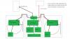
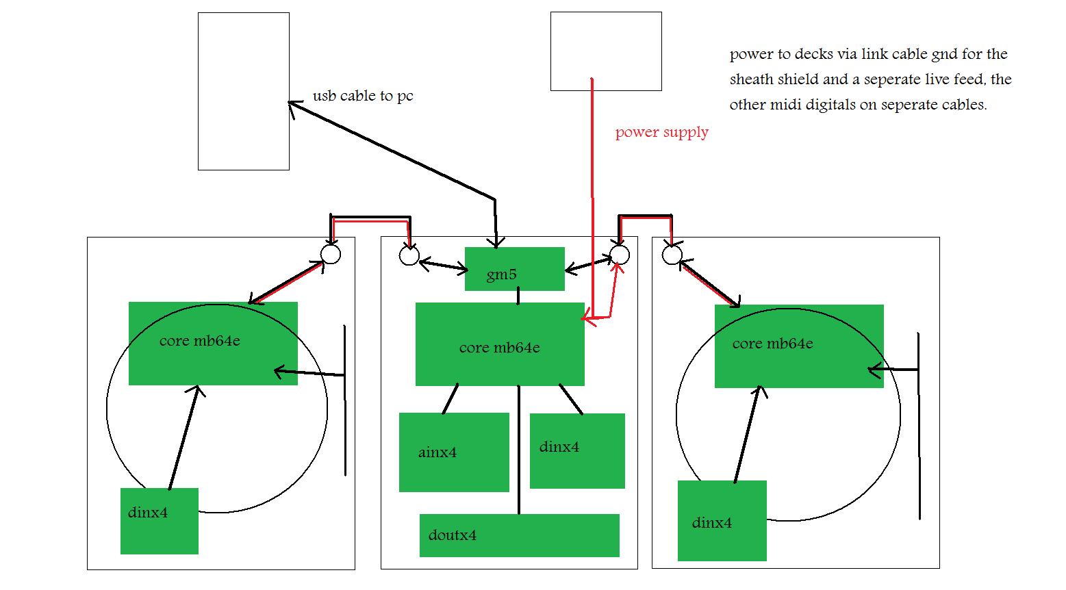
ok in the mixer put a core with a 452 running mb64e youre going to want this for the buttons. also ainx4, dinx4 and a dout for lights should you want them also a 16x2 lcd for built in editing of controls etc, also a 512 bankstick built onto a board as a permanent fixture.
in each deck put a core with a 452 running mb64e 16x2 lcd, you dont need an ainx4 just use the headers off the core, you can ground pins you dont use however if you edit the asm file to just the pins you use, then you dont need to ground the unused ones.
now to link the units.
in the main mixer is a gm5 this is a single usb port with a single midi in and midi out physical port, however, the board still has 5 ins and 5 outs including the port 1 that is there.
to link them you leave the 6n138 ic off the core once assembled, then you link from mi/mo (midi in/midi out) from j11 on the core, these goto the gm5 j6 pins.
so as per this.
mixer core to gm5 mi/mo 1 pins
left deck core to gm5 mi/mo 2 pins
right deck core to gm5 mi/mo 3 pins
now the power, if you get a multiway cable then you can use a mini din socket, 5 pin mini din is fine and then you can have the digital mi/mo links and the shielded power feed also over a single cable to each deck. You can get power supplies that deliver upto 2.5 amps and 7-10volts which the cores need as a wall wart, or laptop style power supply which is what i am using.
when you now connect your decks to the mixer, the mixer connects to your pc via a single usb cable, thats it everything data waise from the decks and mixer is sent back and fore via this single usb cable.
you need to use the built in editor to give each unit its own midi id number as well, this will help when setting things up.
when set up the mixer will have the single usb cable and the psu connection to it, then from the mixer to each deck.
its a much more elegant way of doing things, i will do a diagram later today to explain it visually.
basic picture to give you the idea.
-
The solution that i am using for my traktor set up is to put a gm5 in the mixer controller, then add two ports on the rear to link the two decks to via thier own cores, using the digital in pins on the gm5.
By doing this everything goes through one usb output, so i link the mixer core to midi i/o pin 1 and the left deck to midi i/o 2 and the right to midi i/o 3.
this makes things easier. the link cable is used with mini din sockets and connectors that are available from ebay very cheap along with the cable.
Find all the components that you need, get measurements and do a 1:1 printout to check placement and interference when using.
for the mixer all you need is a core, dinx4, ainx4 the dinx4 will be for the buttons and the ainx4 (you will need several) will be for the faders and pots (rotaries).
The decks will need a core, dinx4 and a single Ainx4.
Should you want indicator lights for the buttons then you will need some doutx4 boards as well.
You can buy actual cdj platters as spare parts from the manufacturers, i just bought two large cdj600 platters from gemini spares in france for under 20 euros. They are around 8 inches or just over in diameter so a large platter/jog wheel which is better than some of the smaller type.
I have to design a custom bearing mount for it that has an encoder attachment at the bottom of it to link to an encoder which will be assigned to the jog/scraatch commands via a shift button.
Here is the platter/jog wheel.

The pitch fader will be a 100mm slimline fader with centre bump and an led to show centre point also.
I know it seems a little daunting but as flemming has said , read read read as much as you can, think of the core and the din, ain and douts as modules and you just link each together via a link cable, each button or encoder etc links to each pin on the relative board. Just think of it as a modular and things will fall into place.
I am using the midibox 64e for mine as this allows the use of encoders as well as pots and faders, the 452 is what you will need for each core.
The bankstick is handy if you want to name each control button, fader etc as this will show in the 16x2 lcd.
Oh and some advice, get the lcds, they come in so handy for programming and debugging, with the mb64e you can edit all the parameters using the built in menu system. Remember the first 8 pins on the first dinx4 board are reserved for the menu system, keep them as is and it will save you many hours of frustration when editing without a computer to hand.
Welcome to the forums!
-
when i click chat i have to put my name in and then #midibox as it does not place it there automatically for some reason.
-
which traktor are you using? traktor-le, pro, scratch??
I have been working on a traktor controller myself, stopped just before xmas to have some down time. I am using some jog wheels from an old gemini cdm3600, i would have liked to have got a pair of platters from a numark cdx or some from the ns7's.
my issue with these controllers is the fact i like the feel of a rotating platter, similar to the hdx or the ns7, that feel of a motorised platter makes things so much nicer than a static jog wheel.
my plan is to have two seperate control units similar to the ns7's and then a centre control unit as the mixer section. the two controllers will link to the centre via 5 pin mini din sockets.
as soon as i get time to get on with things i will put the details up.
-
The mb64e is not that difficult a system to build and is a good start point.
Lets look at a build, first the core, as phunk has said you will want the pic core, the pic sits in a socket so it is not directly soldered to the board so no chance of damaging it with an iron! The rest of the components are easy enough to solder in as they are all through-hole. My advice is to buy a small cheap multimeter from ebay and also a good soldering iron with a selection of tips, a tip cleaner pad and some solder-wick and a solder sucker, basic tools to get on with.
the schematics for the core are on ucapps.de and give value ratings to the location of the parts, also the boards are clearly labeled.
this is also the same for the dinx4 and ainx4 boards, the "chips" or "ic's" sit in sockets and are not soldered directly to the board. As phunk explained the mb64e can use ain's and din's so you can mix pot's , faders and encoders.
a 16x2 lcd is great for debugging and for editing.
so for a traktor controller you will need 2 faders for the pitch, 2 for left and right volume, one for master and one for crossfade.
then you will need upto 28 pots for balance, eq, gain, fx etc these can goto the ainx4 boardsas do the faders, remembering that you will have to set the value for the amount of ain connections in the asm file and recompile so as not to get random values from the ain boards for ungrounded pins.
all buttons will goto the dinx4 boards you can have 8 buttons per shift register so one dinx4 board will take 32 buttons or 16 encoders or a mix. encoders take two pins on a dinx4 board and gnd. this means that each 8 way shift register can only take 4 encoders. Remember that you need to also set the encoders to 40 -+1 speed for NI software, this is done in either the onscreen editor or using the inbuilt editor.
there are many threads on traktor controllers some have been finished, do a forum search for traktor and do some reading up.
-
easiest way to rule out the button is get a fine pair of tweezers or a pice of wire and touch one ned to the pin that it uses and the other to gnd, see if the lcd shows a 0 to 127 jump, if so its the button.
so say your using pin 4 for this button and then its going to to gnd, then all you do is put one end of the tweezer on pin header 4 and the other to gnd (same if using a wire) and if your lcd shos a jump from 0 to 127 then its the button.
one other thing make sure you have the wires going to the right terminals on the button!!
-
i bet more than likely you have it linked wrong, its the most common mistake to make. to stop this happening i only put one row of header pins on my dinx boards.
if you look at the dinx4 board from the top (presuming you have got a smashtv board) you only put the headers on the leftmost outer holes, and the same on the j2 headers also
here is one of my dinx4 boards, the first headers on J1 are only on the leftmost holes and on J2 the inner (left) holes also.

try this, hope it helps.
-
if you have got any ain pins ungrounded this will cause the core to send data. you can either ground all the pins on the core for now, or another easy way is to edit the setup file and set the ain to 0 and the mux to 0 then recompile and then uplaod again to the core, when you do this the core will not send the ain data anymore, this is how i disable the ain on my cores when i have none connected rather than grounding.
-
if you have messaged them through ebay and they havent responded and you are not happy then you need to goto the resolution centre and file a complaint, they will see that you have tried to contact the seller. wait the required period of days then they will refund you.
-
if it were any other person i would be curious but as it is doug i would not worry in the slightest. as we all know doug has been through the wringer lately and his time has not been his own. He is not in the habit of ripping people off, so all i would say is be a little more patient and he will get things sorted.
Doug is a good guy, give him a little time and he will sort things out.
-
i grabbed one of these recently http://cgi.ebay.co.uk/ws/eBayISAPI.dll?ViewItem&item=190457126345
use it most of the time now its a good set up and works well along side my metcal system.
-
hi protosx
with the case what about just having the faceplate made? as that will take the most use and wear, the base can be a stained wood for now, if you want the black look then get an ebony stain and give it several coats, or you can get some mdf cnc cut and then powder coated, mdf can be powdercoated as it has moisture content that allows it to be charged for coating.
Or you could have the lower case made out of acrylic sheet that has been heat bent on the edges to make a box, then fix the metal face to that.
If your stuck for ideas or want help with the face let me know and i will gladly design a face panel for you to the size you need in solidworks in sheet metal format and have it in the correct format for a cnc company if you want.
The biggest cost is the design translation to cnc files for thier machines, if i were to do a full case for you in sheet metal and then map it to a cnc file for a company you would then only be paying for the material and cnc time which would not be much at all then.
have a think on it and get back to me.
ssp
-
Hi protosx.
Let me say some very nice work there!
Now in anser to your question.
You can make a new "patch" or "bank" of settings for the one strip. save this and then make a new "patch" or "bank" for the next strip. You then switch between the different banks.
You can also use the morphing feature to morph between current and saved settings for the controls. You would need several bankstick chips chained together for the amount of storage you want. I know someone on the board recently made some really nice bankstick pcb's recently as i was drooling over them myself! you could ask for a copy of the eagle file and get some made.
With my BPM controller i also use it for other plug-in's so i use the bank change feature for each plug-in i want to use, each plug in is given its own bank and i select the bank for the plug-in in use. The best thing about it is that when you have the bankchip attached you can "name" each button or controller to what ever you want!
I hope this helps.
there is more details on this in the tutorial section for the mb64e on ucapps.de
-
hmm... the forum is not an issue as everything you need to know is here, i gave you two specific links to two sections that dealt with the item you wanted to know about. From that point on its upto you how you proceed to continue on your chosen project, that was an example of what i built to achieve the same thing, it was an "option" presented to you.
The one thing everyone gets told when they want to build things here is to read, read and read some more, i know even i had to learn and i still dont know much but i get by and i also get help from the guys here. The main reason i get help is the fact i have simply made an effort to learn and build things myself before asking the 100 or so questions people invariably do.
anyway, im done, bttd
-
once again search is your friend
-
search is your friend
-
julian the fsrs just wear out, common issue with them, no point doing the sensitivity upgrade its better to just replace the fsr sheet. I got mine from mpc stuff the guys there were great.
when i built the bpm controller i spoke with franklin eventoff who actually designed the fsr its elf and we spoke about it in great deal and he said the only issue with it is that after a period of time they wear and become un-useable.
It is better to replace them when that happens.
-
as its your first post you wont get many offers in here, the best thing to do is to put up some pictures as well so people can see the actual items for sale and see its genuine.
-
wow , thanks guys, i really did not know that i could use c for mb64e and still up it to the 452's. Now i have something to get my teeth into again!
-
hi thorsten.
the reason i stuck with the asm side of things was because i thought that the mb64e was still not ported to the new core unit, at the moment i think it still has not been ported or am i wrong? this was why i stayed using the assembler code.
is it possible to write something in c and still upload it to the 452's? this is what i am not dure of and also what has prevented myself from going to c. Im basically back to noob 101 again!
-
thanks thorsten, i almost see what you mean now, i have some more reading to do again and lots of notes to make so i have reference again. I have been reading all my notes on the meta handler routine we did for the mmc unit and the mmc handlers so i am hoping that by the time i have read everything again and written some test code i will have a grasp of it again.
is it possible to say write something in "c" and then port it to the 452 core?
everyone has said i should move onto "c" now as it makes life much easier, i have found a website with details tutorials and tests so i am neck deep in that also.
so if i get that in my grasp or the basics i will try writing something and uploading the text here to see just how bad it is!.
thanks as always
-
thanks nils, yes i understood that , however that would be in c and the mb64e isnt supporting c code yet.
ok so i just did a few changes to the encoders and realised that to change the patches its a program change not a cc# doh! so i assigned the program change to an encoder and bingo worked first time, so all that has to be done is to apply the two features to two sets of - and + buttons.
-
ok today i did a quick test, using an encoder on a din sr i set the cc# to 0 and the min value to 0 and the max to 5, the reason for this is that the synth has 5 banks. when i turned the necoder it stepped nicely through the banks up and down with the turn of the encoder back and fore. now to apply this to a set of buttons i would need either a -1 or +1 byte assigned to each button, the same with patches. i cant find any subjects on the forum or ucapps that relate to this feature for making patch or bank buttons , the editor only has a bank feature for teh encoders, if you apply it to a button you only have a 0-127 state and a repeat press does not increment the patch it only jumps to the patch at the relative byte value, then back to the first patch on release.
how would i code a small script to achieve this function?
two buttons for bank and two buttons for patch labeled bank- bank+ patch- patch+
so the starting state for bank- is B0 00 00 a press of bank+ changes this to B0 00 01 which sets it to bank 2, pressing bank+ changes it to B0 00 02 which is bank 3, pressing bank- 2 times returns it to B0 00 00 bank 1.
and patch- initail state is C0 00 which is patch 1 then a press of patch+ gives you C0 01 which is patch 2 and then pressing patch- takes you back to C0 00 patch 1. basically the same function set as the banks however for the patches.
i cant find a cc# for patches that allows the stepping through of patches, if i can find this then i could assign an encoder to patches and have a button for the banks.
i am not sure if a step -1 and +1 function would need to be written in or a table of the complete sysex would be needed.
thanks
update: some of the softsynths im using will only respond to the sysex commands for bank and patch change they do not respond to the cc# of cc# 0 for bank and cc#32 for patch.
I want to build a "console"-like controller
in MIDIbox HUIs
Posted
tldr