

ssp
-
Posts
659 -
Joined
-
Last visited
-
Days Won
4
Content Type
Profiles
Forums
Blogs
Gallery
Posts posted by ssp
-
-
Hello stranger! wow long time, you still over at banging tunes then? i haven't been on there in a long time. Still keeping up with mr Parkes though on facebook
I may know someone who could be interested in them. Need an idea of pricing though. let me know what you are thinking of and i can pass the info on, also if needed can you email me over some hi res pics?
thanks
ssp
-
a hair dryer won't nearly be hot enough... you need a heat gun or hot air smt station to heat it up enough.
-
ok the nut is for an encoder, however you can only use it if the hole in the rear mount plate is the same diameter with tolerance as the diameter of the threaded shaft on your encoder, mine was the wrong size it was all they had at the time so i mounted it on a rear mount board. if your using an alps or bourne encoder the centre hole needs to be 9mm, so you may need a 9mm drill bit and make the hole larger so yuu can use the nut the other side.
-
just wondering, did you ground the pins on J5 if you have no analogue inputs or did you change the asm file?
this is from on of my earlier posts:
When i need to test just one or two pots i just connect directly to J5, and i then go into the asm file and change these lines and then recompile, it saves me having to ground things.
So obviously i connect the pots as follows, Pot1: Vs/Vd/A0 Pot2: Vs/Vd/A1 Pot3: Vs/Vd/A2 (connecting to correct pins on pot!!)
So i open for example setup_midibox64e.asm in my text editor
#define DEFAULT_NUMBER_AIN 64 (the amount of pots/faders connected, more than 8 needs an ain board and MUX to be enabled)
#define DEFAULT_ENABLE_AIN_MUX 1 (needed for when you use the ain boards and more than 8 pots)
I then change them to this as i only need say for example 3 pots and no mux as im connected directly and not through an AIN board
#define DEFAULT_NUMBER_AIN 3
#define DEFAULT_ENABLE_AIN_MUX 0
by doing this, the software only looks for the first 3 inputs on J5, the other 5 are not looked at and therefore i do not need to ground them.
So if you do not have any pots or faders then change it to this
#define DEFAULT_NUMBER_AIN 0
#define DEFAULT_ENABLE_AIN_MUX 0
if the J5 pins are not grounded then they cause spurious midi data that is constantly running. As explained changing the code saves soldering!
see if that helps first
Its surprising how easy it is to forget to ground the pins on j5 or edit the asm.
-
heres the midiox data when the fader is pushed up slowly, it has to be a 10bit resolution for the daw to accept it as its default without mapping it.
-
no the nut is for the shaft clamp that grips the encoder /pot shaft.
-
I used this jogwheel from OKW on my bpm controller, the jogwheel is nice and built well however you must get some teflon grease as the wheel will rub on the casing. You will need to make a small mounting board for the encoder as well with the relative screw holes. I am sure i have a spare one here somewhere i will dig it out and put some pics up.
it is a very nice wheel assembly though.
I have bought a lot of items from OKW.
-
Just wondering if anyone can help.
Thorstens away and a little busy at the moment so i am trying to figure things out but not getting far as i have never had to or tried to assign a dual command to one controller in mb64e before and change the resolution.
I need to have an MSB command sent followed by an LSB command straight after when a fader is pushed, this is for my DAW software and allows a finer fader control.
the message sent is:
MIDI RECEIVE EVENT DESCRIPTION
0xb0, 0x00, vv fader value, MSB0xb0, 0x20, vv fader value, LSBSo my assembly on anything other than sysex commands is really bad so i started with this:; This is a 10bit fader command for daw fader control
; B0 (Chan 1 Control/Mode Change)
; 00 (Bank select MSB)
; 00 (This is the Hex value from 00-7f = 0-127)
; 00 (This never changes)
; The second command is the LSB command
; B0 (Chan 1 Control/Mode Change)
; 20 (LSB For Control 0 (Bank Select))
; 00 (This value increments in tens 00 to 70 then repeats this value = 0-127)
; 00 (This never changes)
; MSB command
movlw 0xB0
call MIOS_MIDI_TxBufferPut
movlw 0x00
call MIOS_MIDI_TxBufferPut
; LSB command
movlw 0xB0
call MIOS_MIDI_TxBufferPut
movlw 0x20
call MIOS_MIDI_TxBufferPut
Then after the call is the requirement for the MSB/LSB increment and decrement function when the fader is moved +/-
However i don't understand how i would implement the command for that so i become stuck.
The other issue for me is this needs to be at 10bit resolution so i don't know where i would change that for the mb64e.
Any nudge in the right direction would be appreciated, i want to figure how it would be done.
thanks
-
the midi box ng info states: up to 32 motorfaders connected to MBHP_MF_NG modules
-
sid chip dub step go on you know you want to, get a skrillex midi file and make it really dirty ;)
-
All paid for Jerome, many thanks for those, will have the rest next week, looking forward to building these and putting them to use!
-
hey sauraen, the pcbs look very good, nice to see you are progressing with the build, looking forward to more progress and pictures/videos!
-
need 3 gm5 chips if anyone has them spare, so i can finish my gm5 x 5 boards. thanks
-
I am just wondering if there are any pcb's left spare for sale?
thanks
-
Last time i had to straighten a pcb i just used my solderstations hot air tool and put a large vent tip on and keeping the hot air tool about 15cm away and constantly moving it around in a circle for a few mins until it heated the board up, i then quickly placed a really heavy book on top of it and left it for about 15 mins to cool down, it was fine after that.
-
take a look here.
-
 1
1
-
-
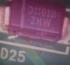
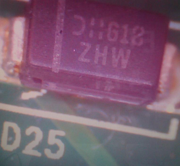
i am looking for a diode but cant find a listing on mouser for the same one or an equivalent, can anyone identify this diode for me? its from a 9v dc feed at 2 amps.
thanks
-
Had some time out recently and just getting ready for a little holiday, so in the downtime i decided to install some new synths and have a play. I was listening to online radio when i head one of deadmau5' new tracks "the veldt" and it stuck in my head all day long. So when everything was plugged in i decided to do a little remake with a different intro and a few changes and see what happened.
The track is not pre or post processed in anyway, i have applied no sidechaning or EQ to the track and as such its a W.I.P and unfinished, hell prehaps i will tidy it up and finish it if i get time.
Until then i thought i would share it with you, oh yes... several midiboxes were used in the making of this track ;)
enjoy!!
-
http://tascam.com/product/fw-1082/specifications/
60mm faders
tascam/teac uk have the fw board in stock at £195 it is simply pulling the old board and installing the new one, on the board there are several "leds" that light up under power, the one for the fw chip and boot section does not light up, after checking it with tascam tech they explained that the fw chip was at fault.
The unit is spotless, no marks at all, if i get no takers as it currently is for conversion i will buy a new main board and relist it here or ebay. I thought someone may get some use out of it as an daw controller unit after modifying the whole thing rather than get the new main board.
-
Selling a tascam FW-1082 its all there but it needs a new main FW board which holds the main boot chip and the FW interface. Tascam/Teac spares quoted me £195 for a replacement board and all is good and it will work but i am not really interesed in repairing it as i am getting an euphonix control setup. I have held onto it as i was going to pull the boards and build a DAW controller using it as it is a perfect pre-made layout. With the motor faders illuminated buttons, transport etc it would have been a good conversion into a control surface.
I am not looking at much for it, i will take £100 for the unit plus postage. I will put up some pictures later on so you can see the units condition. I can send it via overnight courier service please be aware that if i send it abroad the postage may be slightly higher.
-
I'm looking for a small 12mm also encoder with a push to make shaft switch, now if anyone knows of something else thats fine but even better if it has a led built in as well. Thanks
ok all sorted now thanks. found what i needed today.
-
When i need to test just one or two pots i just connect directly to J5, and i then go into the asm file and change these lines and then recompile, it saves me having to ground things.
So obviously i connect the pots as follows, Pot1: Vs/Vd/A0 Pot2: Vs/Vd/A1 Pot3: Vs/Vd/A2 (connecting to correct pins on pot!!)
So i open for example setup_midibox64e.asm in my text editor
#define DEFAULT_NUMBER_AIN 64 (the amount of pots/faders connected, more than 8 needs an ain board and MUX to be enabled)
#define DEFAULT_ENABLE_AIN_MUX 1 (needed for when you use the ain boards and more than 8 pots)
I then change them to this as i only need say for example 3 pots and no mux as im connected directly and not through an AIN board
#define DEFAULT_NUMBER_AIN 3
#define DEFAULT_ENABLE_AIN_MUX 0
by doing this, the software only looks for the first 3 inputs on J5, the other 5 are not looked at and therefore i do not need to ground them.
Hope this helps
-
you will need to remove all the knobs, then unscrew the base casing, then unscrew the board from the housing, when the board is out, you then need to unsolder the pots that are at issue. You can then if they have tabs bend them back and clean the tracks inside with some isopropyl and some cotton buds/q-tips. when dry re-assemble and then re-solder to the board and put it all back together. You can also buy the replacement pots from vestax spares, you can also buy compatibles from the internet but you need to know what ohm rating they are. You cant just use any pot in there.
Finally if you cant fix it goto the vestax web site and look for a service agent in your area and let them fix it for you.
-
Here are two tracks that i have written.
The first is a track called Beltram, after another producer i know Joey beltram. After speaking with joey and making some revisions etc i decided not to commercially release the track. There were other things i wanted to do and the track still remains a part of my personal library. It is un eq'd, with no processing or mastering. PArts are missing that i didnt bounce down with it but you can listen to it in its last state.
Enjoy
http://soundcloud.com/pherik/beltram
This track is a remake of the seminal trance track from Paul Van Dyk, "For and angel" was a track i wanted to remake and give justice to for years. I finally started on the track early in 2011, however after many attempts to get an acoustic drum section in that i liked i put the track on hold. I really want to get the track finished but i now have ideas about adding live string sections also, so it wont be ready for some time yet. In the meantime enjoy this preview which is unmastered or processed. The break is long however when the acoustic drums are in there the break becomes totally different.
Enjoy.
gm5x5x5 Bulk Order #4 - spares
in Bulk Orders
Posted
I need some gm5 chips for my remaining boards so if there are chips for sale i will take them ;)