

ssp
-
Posts
659 -
Joined
-
Last visited
-
Days Won
4
Content Type
Profiles
Forums
Blogs
Gallery
Posts posted by ssp
-
-
I am also wondering about condition lables
COND
CONDitional labels are the most powerful purpose of global label definitions - they allow to output different strings based on the EVENT value!
Following example demonstrates the purpose pretty nicely:
COND_LABEL fil_type
COND =0    "Bypass   "
COND =1    "LP 24dB  "
COND =2    "LP 12dB  "
COND =3    "BP 24dB  "
COND =4    "BP 12dB  "
COND =5    "HP 24dB  "
COND =6    "HP 12dB  "
COND =7    "Notch24dB"
COND =8    "Notch12dB"
COND =9    "Comb+    "
COND =10   "Comb-    "
COND =11   "PPG LP   "
COND_ELSE  "Type %3d "
An EVENT_* command can use it this way:
# this command is part of a .NGC file:
EVENT_ENC id=1  type=CC cc=16  lcd_pos=1:1:1 label="Filter Type: ^fil_type"
How does this line call say COND =8 "Notch12dB"?
-
ok after talking with latigid on it seems the penny dropped
so, EVENT_BUTTON id=1 type=NoteOn key=36 lcd_pos=1:1:1 label="Button #%3i: %3d
1: EVENT_BUTTON id=1 this references the button on sr=1 (shift register 1 pin D0)
2: type=NoteOn key=36 this references the midi event generated (midi noteon key=36, this has a range of 0-127)
3: lcd_pos=1:1:1 This references the lcd say a 2x20 (the first 1 references the first lcd connected, the second "1" references the first line of the lcd the "upper line", the third "1" is the starting character of the lcd and the generated text of the event name mapped tothe button)
4: #%3i: %3d this references the spacing"padding" of the characters in the display (%3i is a padding of "3" before the event id "i" and the %3d is also referencing padding)
Once my core arrives i can play around with this to get a better understanding however if i were to change the string to this #%2i %2d the padding woud be of two characters spacing
%i is the event-id %d is the value so if the value is 54 it will show "54" as the value, then the lcd displays (noteon 54) on the lcd.
A couple of days in and its sinking in, thanks again for the help
-
most of the code is ok to understand its actually simpler than the old assembly on the older cores. its just some of this syntax use to define variables to the end of the statement.
-
its a section not properly explained in the info, this is the first time i have taken a look at the NG. so does %3 mean there are 3 spaces before the display shows a character? I have ordered a brick to hit myself over the head at some point to try and understand this! lol
-
ok so this is:
%3i The "i" is the id of the event as stated above ( %i: the ID of the EVENT ) and the %3i means the event will be padded with spaces to 3 characters
%3d This is also padded with spaces to 3 characters
I do not have a completed MB_NG here to try this so I am guessing in the dark on this so bear with me.
Please define "padding" as i find no reference to its meaning.
-
I am getting to grips with the code however, can someone enlighten me on the last section of this example string>
EVENT_BUTTON id=1 type=NoteOn key=36 lcd_pos=1:1:1 label="Button #%3i: %3d" what is this section referencing/meaning? #%3i: %3d
so when i look at this i see
(EVENT_BUTTON id=1) the button id is 1 this is the first button on D0
(type=NoteOn key=36) the midi event it is producing is a note on key value 36
(lcd_pos=1:1:1) it is shown on lcd 1, line 1, (what is the 3rd 1 for?)
(label="Button #%3i: %3d" ) and you got me here... no clue!!
Thanks
-
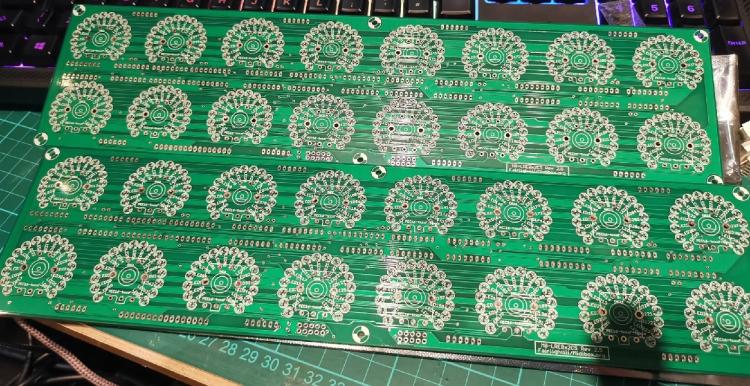
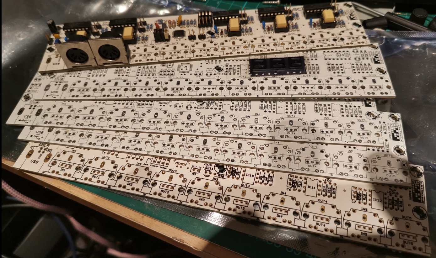
Found these today, forgot I had these all put away for a rainy day. Also found a load of boards I had got from Smashtv as well this makes things a lot easier now as I dont have to really order anything else than those I have just ordered.

-
I just picked up an stm32f discovery board from farnell. I have updated the firmware and flashed the bootloader and mios first go!! slowly reading through the first steps and getting to grips with this, I am an old pic guy so this is a little jump for me.
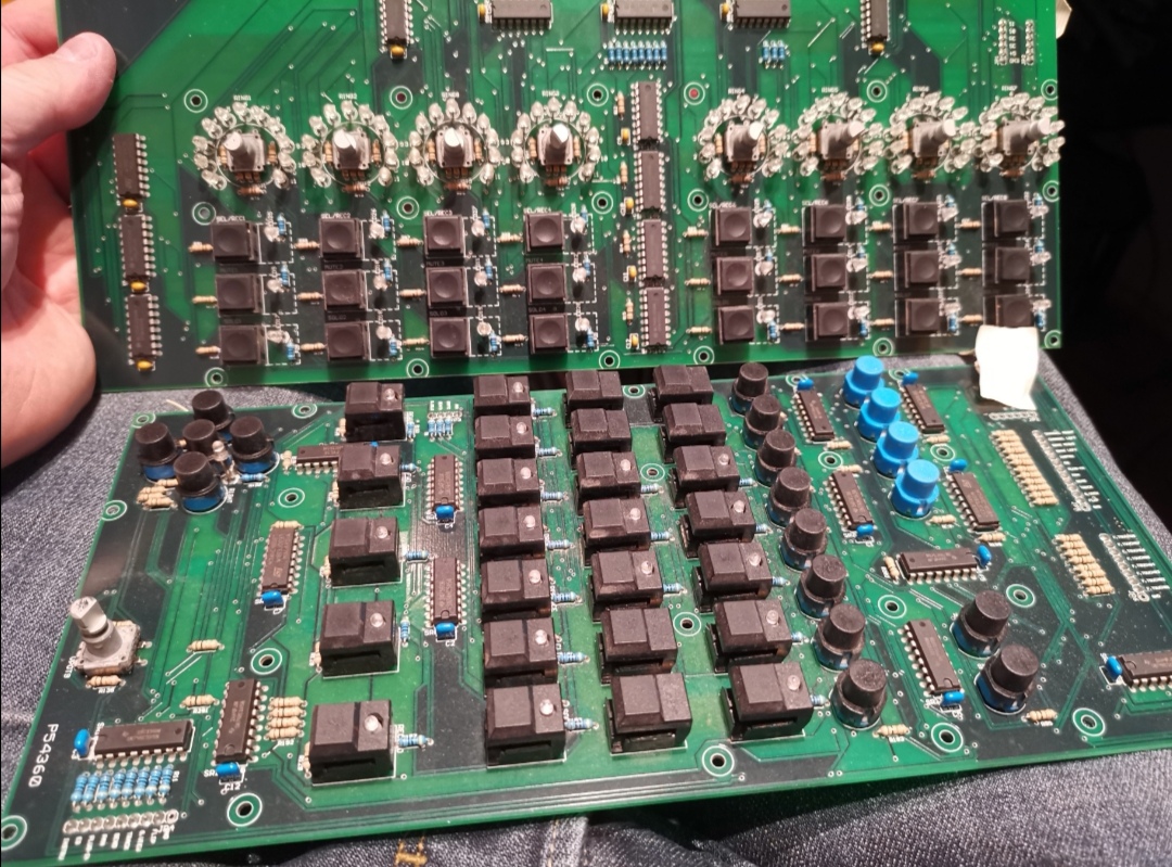
Got a few boards on the way from modular addict, going to build a mackie clone over the winter. I recently grabbed a cheap mb_lc on ebay and i decided to keep the two good pcbs and rebuild the rest. Had some display issues but got new ones in and all is good however, i see that you can use SSD1306 displays with the NG, I would like to use these over each fader and also have an MTC display as well.
The MTC displays i have built before using the old midimon, so i will look to build a segment display again.
What info do i need to know or search the forum for in relation to setting up and editing code for the SSD1306?
This will be a fun project over the winter!
-
the boards are well made, plenty of connection identifiers in the silkscreen, some led connections are missing and they are soldered to pads under the pcb and wired around it which i will sort out in work by adding some connect pins.
There is no info on these boards on the server, i did notice that Dan D2K used them in his mblc units but there is no info there in the forum thread, its old and any links are long gone, they are easy to understand the circuit paths etc but more info would be good as well as placement and position etc from a new front panel, I am hoping the Holt who did the original case still have some details.
-
i picked up a pickit 3 programmer and made a pic socket link pcb in work. uploaded the bootloader to the pic then mios and all was good ;) its been a while since i was here and its all coming back!! hurrah!
just have to wait for my bits to arrive from modular addict which is always the bit that is annoying, i remember waiting for kits from smashtv!!
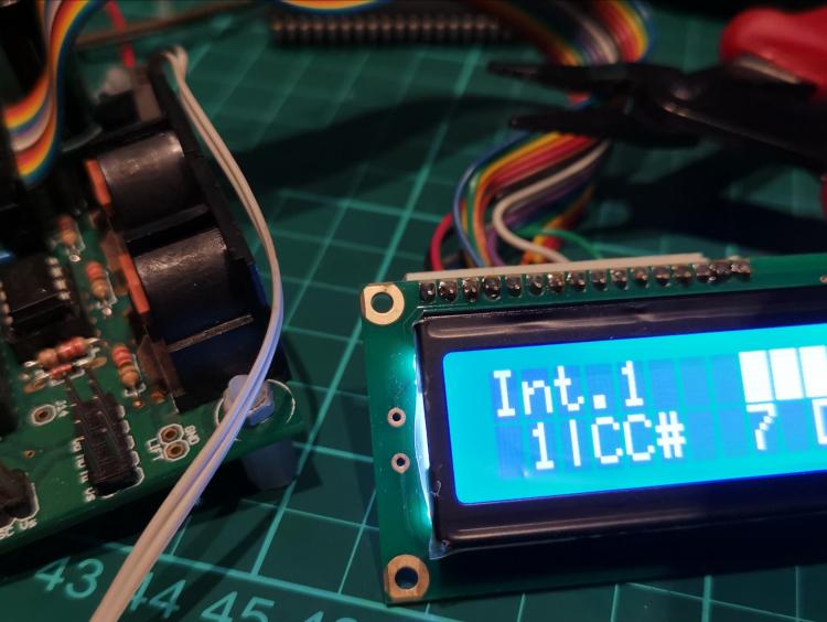
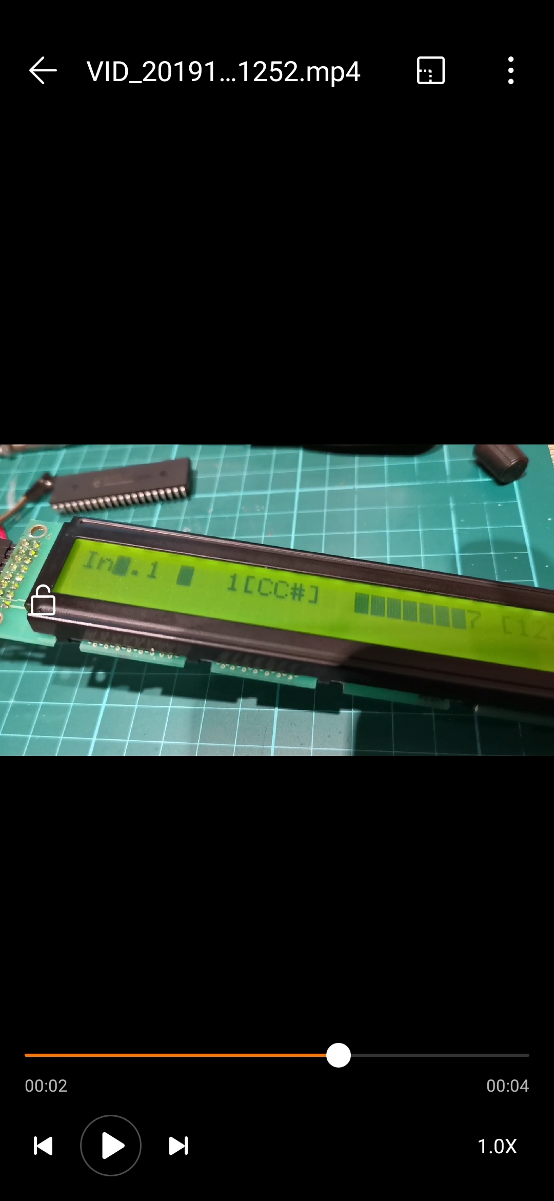
the picture above was from an old core and wasnt displaying properly on the new lcd, a quick bit of code and all is well again, no spaces etc.
I am trying to find out the details on the pcbs that were inside the unit and also details on the layout on the Holt case that it came in.
If anyone has any details on the boards let me know!.

-
The new displays turned up today, all is good. Working first time, the old ones will be used for something else. I have a load of stuff on order from modular addict. Need to build a few controller's for the studio.

-
I used the original core from the mblc it's the v0 pin it wants a neg 0.3v link. This old lc had a separate power link board that gave it that. Had a dig around it last night. They are very old displays now, much better options are available now. Replacements arrive tomorrow I am just playing with this until my other parts arrive from modular addict. Making a newer controller with the new mf board etc. I just wanted to have a fudge with this old mblc
-
there is no datasheet for this model anywhere however, looking at close variants the v0 needs 0.3v negative feed. Seeing as these are old lcds anyway I am going to change them out for a pair of new winstars
-
Same core my test lcd
-
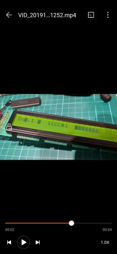
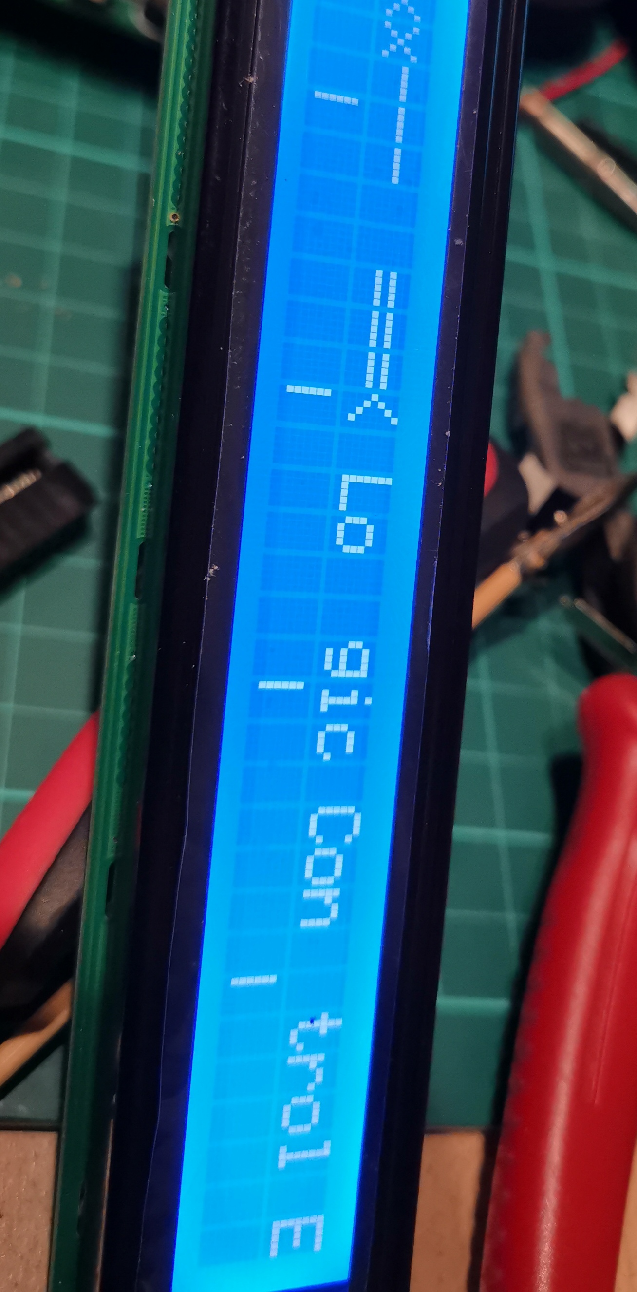
OK this is weird if I turn the core on and off I randomly get the display graphics come up for a fraction of a second then go back to being really faint. Contrast makes everything dissappear still.
-
bit of a head pickle here, i have one of the 40x2 lcds connected to a good core that i use for build tests.
With my usual lcd attached all is fine in backlight and contrast.
I have connected the 40x2 and the backlight is good however the lettering is very very faint, contrast seems to have no effect when i turn the pot other than it dissapears.
my core has the 7805 vreg on, i am just wondering if its not getting enough voltage, it displayed good on the old core board from the unit, but it was covered in really bad soldering.
there are new connection pins on the lcd and i have measured the voltage from both pots p1 and p2 and i get the correct voltages.
checked the link cables which are pushon with the multimeter and all is good.
bit strange this one.
The lcds are the TM402cd from tianma https://www.beyondinfinite.com/lcd/Library/Tianma/TM402CBCWVBYA.pdf
connection is standard.
any ideas?
thanks
-
All is good i have managed to dig up all the old information scattered over the forum pages and other places.
There are two professionally produced pcbs in this thing that i still have not found out any information about yet, i will put up some pics incase someone may be able to help, other than that im fine, it all came flooding back and im already working on the casework and upgrades.
Thanks
-
Picked up an old midibox lc off ebay cheap, it powers on fine and seems ok.
Its not a unit that I am familiar with but its something for me to tinker with in these winter evenings.
Couple of questions,
1: the core's are old home made cores , I still have a couple of smash tv's core 8 pcbs here, can i replace the others with those, I am assuming i can
2: the MF was replaced with the MF_NG so I am going to buy one of those to replace the old MF pcb I see this can be linked to the pc directly rather than the cores. Anything else i should know on this replacement?
Plan is the put one of my old GM5 midi interface boards in there and have the MF_NG and the cores midi route into that then out via usb as i have done on previous projects.
This one boots up with the message logic control emulation, is this the same protocol for use in Mackie HUI mode or is it a different set of settings i cant for the life of me remember if the logic protocol is the mackie protocol or if its a different settings hex file that needs to be uploaded for it to be a mackie HUI configuration.
If anyone still has an old LC kicking around or has modified theirs to a better setup I would love to chat about it and pick some tips up while i tinker with this. The wiring needs re-newing and the casework is going to be media blasted and powdercoated in the meantime.
Thanks
SSP
-
search and you shall find.. yep its been done before..
-
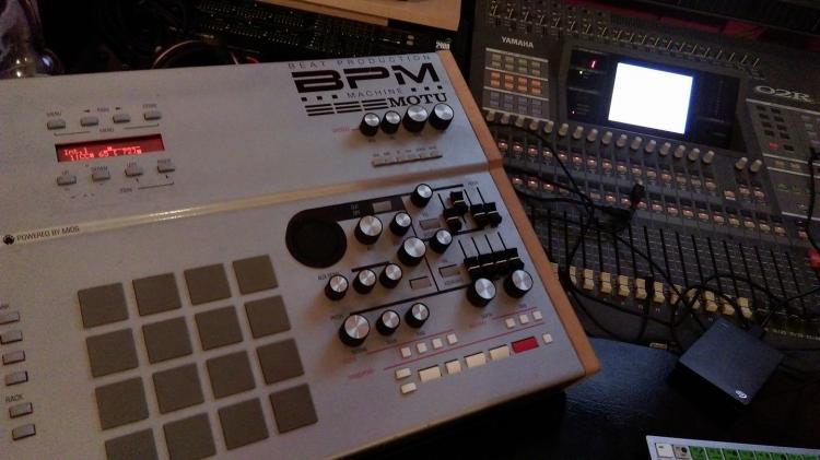
Just popped in as I am currently building a new self contained synth, still using this Bad Boy after all these years. Never let me down once!!
-
only just saw this, been a while since i was last here. weird no one referred you to my thread. here you go.
-
Here you go i built one a while ago it does everything that a daw needs.
-
Hey sauren, its been a while since i had a chance to pop in here. Really nice to see how far you have come with the project. I cant wait to see it all cased up and finished. Well done, glad to see you stuck at it!!!
-
Been away a while, still busy making blue smoke and still writing music and producing. here is the last revision of beltram, now mastered up and re-eq'ed. Enjoy!!


understanding the .ngc code
in MIDIbox NG
Posted · Edited by ssp
Really enjoying this code, its easier to understand than assembly was for me, i showed my work colleage today who still uses delphi for some of our test software and he said it had some similarities to delphi.
I dare say i will have a couple more questions as i go, but as i learn i will put up diagrams to show what I have learned and its use and effects to help new members who also want to learn the code for the NG.
I printed out all of the user manual files for first steps, ngc, ngl, ngr etc as it makes it easier to sit and read instead of staring at the computer screen besides, i like to be able to highlight or mark something thats relevent and i need to try.
On a plus point my boards arrived from Modular addict today, Gotta order a couple more though but now i can start on the new motorfader module.