

mastomo
-
Posts
68 -
Joined
-
Last visited
Content Type
Profiles
Forums
Blogs
Gallery
Everything posted by mastomo
-
-
-
great !!!! i'm in :flowers: my name is on this bulk order list
-
upload is done !!! everything is fine :ahappy:
-
i love it too !!!! my mbseq V4 is great and i'm using it for live playing, a smaller one could be really cool !!! i will follow this carefully !!! TK you're amazing, you know this of course ????
-
i just can't wait for the "it's ready" message ! Tim, we love you, do you know this ??? :flowers:
-
i love it !!!
-
ok, i've got the switches since this morning. they are really cool !!! thanks to you Doug take care of you :-)
-
beta33 is cool. everything is ok by my side
-
 this is really cool !!! i love it
 -
Hello TK, i just send you a PM with a link for a session. this session will match with a GM module. btw, i'm really happy today because i'm leaving Paris this morning for one week. i'm going to play my music in St Louis Senegal for a festival. :clover: of course i'm bringing my MBSeq V4 to play with it. :smile: i will try to take some nice pictures of this. have a nice day
-
hello everyone, something weird is happening since my last update (Beta31) here is the thing : Pattern A1 G1T1 plays drums for OUT1 midi channel 10 Pattern A2 G1T1 plays bass for OUT1 midi 1 Pattern A3 G1T1 plays drums for midi channel 10 i'm starting with A2, everything is fine. - > stop change to A1 - > play : G1T1 is playing, but my drum's synth is not receiving any messages. - > stop change to A3 : everything is fine change to A1 : everything is fine my solution is really easy : all my patterns got the same shape. G1T1 channel 10, G1T2 channel 1, G1T3 channel 2 and G1T4 channel 3. hope i make it clear.
-
this is absolutely great, and it works !!! thousand thanks :flowers:
-
here is one more happy face :flowers:
-
Hello everyone, that is great ! another subject, there is something that seems weird to me : about song mode. if my song start with pattern A1 and if in the pattern screen i've choose A2, then when i'm playing my song, the first step is from A2 and not from A1. sometime, this is a problem, specially when i play song 1 and then song 2. the first step is not the good one. hope i'm making clear... best regards
-
i agree with this ! but because you're asking, i'm using this SEQ since 3 month and personally, i never use datawheel. i also never use those switches : metronome, scrub, pause, rew and fwd. my seq V4 is a standard one, with 44 buttons. one buttons that i consider as a non essential one is : solo but, i'm thinking of one which might be useful : tempo preset. all the others buttons seems to me essential. best regards
-
Hello TK, hello everyone, is it possible to reorganize pattern between differents sessions ? if yes, i can't find the procedure. if no, is it possible in future ? that would be a great things for me. btw, i'm playing this new midibox on stage since 2 weeks, and this is amazing, once again, many thanks for this :flowers:
-
Hello everyone, i'm trying to send SysEx messages from my MBSeqV4. i have created a SysEx file into the SD Card, but after this, i don't know what to do ... thanks for your help
-
Hi Julien, i'm writing in english for everyone can read it :flowers: the only things i've change is the chapter #LED assignments to DOUT pins# but, you seems right, i don't need to enable button matrix. indeed, i think i found my mistake. Once more, it seems to be a story of crap soldering .... when i disable track 1 to 4 and layer A, B, C everything is fine and i can change the MBSEQ_HW.V4 file as i want and there is no bugg anymore. sorry for this short topics Thomas
-
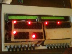
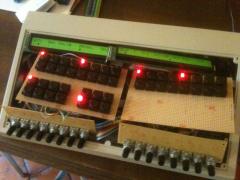
Hello, my sequenceur MIDIbox SEQ V4 is still hot from soldering. i'm discovering it and find it amazing !!! (many thanks TK for this) here is the point : i'm trying changing the MBSEQ_HW.V4 file. when i copy the standard_v4 files into the SD Card, everything is OK except that LED don't light on where i would like. so, i'm changing the file, and then, LED light on where i want to BUT there is a small bugg --->>> by a sort of random way, every LED light on together, then it goes, then it comes back... here is my new MBESQ_HW.V4 if someone get a clue ... best regards ################################################## # Setup File for Standard Frontpanel # $Id: MBSEQ_HW.V4 1025 2010-05-24 14:13:26Z tk $ ################################################## ################################################## # MIDI Remote Keyboard Function ################################################## # The note number which activates the remote function # 96 = C-7 (by some MIDI monitors displayed as C-8) # 0 disables the remote keyboard function MIDI_REMOTE_KEY 96 # The CC number which activates the remote function # (e.g. to control it with a footswitch) # Allowed numbers: 1-127 for CC#1..CC#127 # 0 disables the function (default) MIDI_REMOTE_CC 0 ################################################## # Running status optimisation # Enabled by default, should be disabled if a MIDI # device connected to a MIDI port doesn't fully # comply to the MIDI specification. # Expects two parameters: port number and 0/1 to # disable/enable the optimisation. ################################################## # OUT1 (MIDI1 port of MBHP_CORE_STM32 module) RS_OPTIMISATION 0x20 1 # OUT2 (MIDI2 port of MBHP_CORE_STM32 module) RS_OPTIMISATION 0x21 1 ################################################## # Shift Register Setup ################################################## # number of first and second DOUT shift register used for GP LEDs GP_DOUT_L_SR 3 GP_DOUT_R_SR 4 # DOUTs for Dual Color option: GP_DOUT_L2_SR 0 GP_DOUT_R2_SR 0 ################################################## # Optional BLM Matrix ################################################## # set this value to 1 if each track has its own set of 16 LEDs to display unmuted steps and current sequencer position # or if you are using a button/led matrix for misc. button/LED functions BLM_ENABLED 0 # define the shift registers to which the anodes of these LEDs are connected # Note: they can be equal to GP_DOUT_[LH]_SR, this saves two shift registers, but doesn't allow a separate view of UI selections BLM_DOUT_L1_SR 6 BLM_DOUT_R1_SR 9 # define the shift register to which the cathodes of these LEDs are connected # Note that the whole shift register (8 pins) will be allocated! The 4 select lines are duplicated (4 for LED matrix, 4 for button matrix) # The second DOUT_CATHODES2 selection is optional if LEDs with high power consumption are used - set this to 0 if not used BLM_DOUT_CATHODES_SR1 5 BLM_DOUT_CATHODES_SR2 8 # set an inversion mask for the DOUT shift registers if sink drivers (transistors) # have been added to the cathode lines # Settings: 0x00 - no sink drivers # 0xf0 - sink drivers connected to D0..D3 # 0x0f - sink drivers connected to D7..D4 BLM_DOUT_CATHODES_INV_MASK 0x00 # 0: no DUO colour LEDs are connected to the LED matrix (position marker inverts step LED) # 1: DUO colour LEDs are connected to the LED matrix, second LED displays position marker # 2: Like option 1, but the first LED is turned off when the position marker activates the second LED BLM_DOUT_DUOCOLOUR 1 # define the shift registers to which the anodes of the "second colour" (red) LEDs are connected BLM_DOUT_L2_SR 7 BLM_DOUT_R2_SR 10 # set this to 1 if a button matrix is connected BLM_BUTTONS_ENABLED 1 # set this to 1 if these buttons should only control the "step triggers" (gate, and other assigned triggers) - and no UI functions BLM_BUTTONS_NO_UI 1 # define the DIN shift registers to which the button matrix is connected BLM_DIN_L_SR 11 BLM_DIN_R_SR 12 ################################################## # Additional 8x8 BLM as used for Wilba's Frontpannel ################################################## # set to 1 to enable 8x8 BLM driver BLM8X8_ENABLED 0 # to which shift register are the select lines connected? # Allowed values: 0 to disable, 1..16 to assign shift register BLM8X8_DOUT_CATHODES_SR 1 # set an inversion mask for the DOUT shift registers if sink drivers (transistors) # have been added to the cathode lines BLM8X8_DOUT_CATHODES_INV_MASK 0x00 # to which shift register are the LED anode lines connected? # Allowed values: 0 to disable, 1..16 to assign shift register BLM8X8_DOUT_LED_SR 2 # 0: no mapping of 8x8 LEDs # 1: enable GP LED -> 8x8 matrix mapping for Wilba's MB-SEQ PCB BLM8X8_DOUT_GP_MAPPING 1 # 8x8 matrix for misc. button functions BLM8X8_DIN_SR 2 ################################################## # CV and Gate/Trigger/Sync Setup ################################################## # define the AOUT interface which is connected to the core # 1: a MBHP_AOUT module # 2: up to 4 (chained) MBHP_AOUT_LC modules in 8/8 bit configuration # 3: a MBHP_AOUT_NG module AOUT_INTERFACE_TYPE 1 # additional gate triggers are available on common digital output pins of the # DOUT shift register chain - they are assigned to AOUT channel #16 (Note C-1, C#1, D-1, ...) # define the shift registers which should be used here (each provides 8 gates) # Note that SRs assigned to this function cannot be used as LED outputs (exclusive function) # Allowed values: 1-16, 0 disables the function, all other values invalid and not allowed DOUT_GATE_SR1 0 DOUT_GATE_SR2 0 DOUT_GATE_SR3 0 DOUT_GATE_SR4 0 DOUT_GATE_SR5 0 DOUT_GATE_SR6 0 DOUT_GATE_SR7 0 DOUT_GATE_SR8 0 # if set to 1, the DOUT "gates" will send 1mS pulses # useful for analog drums DOUT_1MS_TRIGGER 0 # should J5A/B/C outputs be enabled (0: no, 1: yes, 2: yes, but in open drain mode)? # - the 8 AOUT gates will be forwarded to J5A/B # - DIN sync clock will be forwarded to J5C:A0 # - DIN sync start/stop will be forwarded to J5C:A1 # - if open drain mode enabled (option 2), external pull-ups have to be connected to J5 pins # (advantage: pin levels can be pulled to 5V) # # NEVER USE THIS TOGETHER WITH ANALOG POTS - IT WILL CAUSE A SHORT CIRCUIT! J5_ENABLED 1 # pulsewidth of DIN sync clock (1..250 mS) DIN_SYNC_CLK_PULSEWIDTH 1 ################################################## # LED assignments to DOUT pins # SR = 0: LED disabled # SR = 1..16: directly forwarded to DOUT pin # SR = 17..24: forwarded to a 8x8 LED matrix ################################################## # SR Pin LED_BEAT 0 0 # SR Pin LED_PAR_LAYER_C 1 1 LED_PAR_LAYER_B 1 2 LED_PAR_LAYER_A 1 3 # SR Pin LED_TRACK4 1 4 LED_TRACK3 1 5 LED_TRACK2 1 6 LED_TRACK1 1 7 # SR Pin LED_EDIT 2 7 LED_MUTE 2 6 LED_PATTERN 2 5 LED_SONG 2 4 # SR Pin LED_SOLO 2 3 LED_FAST 2 2 LED_ALL 2 1 # SR Pin LED_GROUP1 11 0 LED_GROUP2 11 2 LED_GROUP3 11 4 LED_GROUP4 11 6 # SR Pin LED_TRG_LAYER_A 0 0 LED_TRG_LAYER_B 0 1 LED_TRG_LAYER_C 0 2 # SR Pin LED_PLAY 0 0 LED_STOP 0 0 LED_PAUSE 0 0 LED_REW 0 0 LED_FWD 0 0 LED_LOOP 0 0 LED_FOLLOW 0 0 # SR Pin LED_EXIT 0 0 LED_SELECT 0 0 LED_MENU 0 0 LED_SCRUB 0 0 LED_METRONOME 0 0 LED_RECORD 0 0 LED_UTILITY 0 0 LED_COPY 0 0 LED_PASTE 0 0 LED_CLEAR 0 0 LED_UNDO 0 0 # SR Pin LED_STEP_VIEW 0 0 LED_PAR_LAYER_SEL 0 0 LED_TRG_LAYER_SEL 0 0 LED_TRACK_SEL 0 0 # SR Pin LED_TAP_TEMPO 0 0 LED_TEMPO_PRESET 0 0 LED_EXT_RESTART 0 0 # SR Pin LED_DOWN 0 0 LED_UP 0 0 # SR Pin LED_MORPH 0 0 LED_MIXER 0 0 LED_TRANSPOSE 0 0 ################################################## # Button assignments to DIN pins # SR = 0: Button disabled # SR = 1..16: directly triggered from DIN pin # SR = 17..24: triggered from a 8x8 button matrix ################################################## # SR Pin BUTTON_DOWN 1 0 BUTTON_UP 1 1 BUTTON_LEFT 0 0 BUTTON_RIGHT 0 0 # SR Pin BUTTON_SCRUB 1 2 BUTTON_METRONOME 1 3 BUTTON_RECORD 0 0 # SR Pin BUTTON_STOP 1 4 BUTTON_PAUSE 1 5 BUTTON_PLAY 1 6 BUTTON_REW 1 7 BUTTON_FWD 2 0 BUTTON_LOOP 0 0 BUTTON_FOLLOW 0 0 # SR Pin BUTTON_MENU 2 5 BUTTON_SELECT 2 6 BUTTON_EXIT 2 7 # SR Pin BUTTON_TRACK1 3 0 BUTTON_TRACK2 3 1 BUTTON_TRACK3 3 2 BUTTON_TRACK4 3 3 # SR Pin BUTTON_PAR_LAYER_A 3 4 BUTTON_PAR_LAYER_B 3 5 BUTTON_PAR_LAYER_C 3 6 # SR Pin BUTTON_EDIT 4 0 BUTTON_MUTE 4 1 BUTTON_PATTERN 4 2 BUTTON_SONG 4 3 # SR Pin BUTTON_SOLO 4 4 BUTTON_FAST 4 5 BUTTON_ALL 4 6 # SR Pin BUTTON_GP1 7 0 BUTTON_GP2 7 1 BUTTON_GP3 7 2 BUTTON_GP4 7 3 BUTTON_GP5 7 4 BUTTON_GP6 7 5 BUTTON_GP7 7 6 BUTTON_GP8 7 7 BUTTON_GP9 10 0 BUTTON_GP10 10 1 BUTTON_GP11 10 2 BUTTON_GP12 10 3 BUTTON_GP13 10 4 BUTTON_GP14 10 5 BUTTON_GP15 10 6 BUTTON_GP16 10 7 # SR Pin BUTTON_GROUP1 13 0 BUTTON_GROUP2 13 1 BUTTON_GROUP3 13 2 BUTTON_GROUP4 13 3 # SR Pin BUTTON_TRG_LAYER_A 13 4 BUTTON_TRG_LAYER_B 13 5 BUTTON_TRG_LAYER_C 13 6 # Following button functions are usually assigned to Fx # buttons, or to dedicated (labeled) buttons # In the standard frontpanel layout: # F1 is located at SR 2 Pin 1 # F2 is located at SR 2 Pin 2 # F3 is located at SR 2 Pin 3 # F4 is located at SR 2 Pin 4 # SR Pin BUTTON_UTILITY 2 1 BUTTON_STEP_VIEW 2 2 BUTTON_TRG_LAYER_SEL 2 3 BUTTON_TRACK_SEL 2 4 BUTTON_PAR_LAYER_SEL 0 0 # SR Pin BUTTON_TAP_TEMPO 0 0 BUTTON_TEMPO_PRESET 0 0 BUTTON_EXT_RESTART 0 0 # SR Pin BUTTON_COPY 0 0 BUTTON_PASTE 0 0 BUTTON_CLEAR 0 0 BUTTON_UNDO 0 0 # SR Pin BUTTON_MORPH 0 0 BUTTON_MIXER 0 0 BUTTON_TRANSPOSE 0 0 ################################################## # Button behaviour # 0: active mode so long button pressed # 1: pressing button toggles the mode ################################################## BUTTON_BEH_FAST 1 BUTTON_BEH_ALL 1 BUTTON_BEH_SOLO 1 BUTTON_BEH_METRONOME 1 BUTTON_BEH_LOOP 1 BUTTON_BEH_FOLLOW 1 BUTTON_BEH_SCRUB 0 BUTTON_BEH_MENU 0 BUTTON_BEH_STEP_VIEW 0 BUTTON_BEH_TRG_LAYER 0 BUTTON_BEH_PAR_LAYER 0 BUTTON_BEH_TRACK_SEL 0 BUTTON_BEH_TEMPO_PRESET 0 ################################################## # Special Behaviour of ALL button # 0: only parameter layers are modified by ALL function # 1: trigger and parameter layers are modified by ALL function ################################################## BUTTON_BEH_ALL_WITH_TRIGGERS 0 ################################################## # Encoder Functions # SR = 0: encoder disabled # SR = 1..16: DIN assignment # Types: NON_DETENTED, DETENTED1, DETENTED2, DETENTED3 ################################################## # SR Pin Type ENC_DATAWHEEL 1 0 DETENTED2 # the speed value for the datawheel which is used when the "FAST" button is activated: ENC_DATAWHEEL_FAST_SPEED 3 # SR Pin Type ENC_GP1 5 0 DETENTED2 ENC_GP2 5 2 DETENTED2 ENC_GP3 5 4 DETENTED2 ENC_GP4 5 6 DETENTED2 ENC_GP5 6 0 DETENTED2 ENC_GP6 6 2 DETENTED2 ENC_GP7 6 4 DETENTED2 ENC_GP8 6 6 DETENTED2 ENC_GP9 8 0 DETENTED2 ENC_GP10 8 2 DETENTED2 ENC_GP11 8 4 DETENTED2 ENC_GP12 8 6 DETENTED2 ENC_GP13 9 0 DETENTED2 ENC_GP14 9 2 DETENTED2 ENC_GP15 9 4 DETENTED2 ENC_GP16 9 6 DETENTED2 # the speed value for GP encoders which is used when the "FAST" button is activated: ENC_GP_FAST_SPEED 3 # Auto FAST mode: if a layer is assigned to velocity or CC, the fast button will be automatically # enabled - in other cases (e.g. Note or Length), the fast button will be automatically disabled ENC_AUTO_FAST 1
-
 Great !!! everything is perfect, i'd like the same :turned:
 -
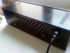
fair enough ! here is some with my 2 Synth from Vermona. i am not really proud of the ugly design... but it works. as i was not sure to be able to finish this project, i do not spend too much money with the design. but now, things are different. i will find a way to make it looking cool :-) moreover, i love this community and i must admit that the amount of knowledge is amazing. best regards
-
Hi, just a short message because my seq V4 is done ! I am really happy of course, and the choise of the v4 was the right one : i cant imagine the seq without the drumtrack, without USB,... Thanks again for your precious advice. Wish you a nice summer
-
Core Stmp32 Module - about J2 jumper - IC6 regulator 7805
mastomo replied to mastomo's topic in MIDIbox SEQ
Hi there, a short message because my sequenceur is done ! I'm really happy of course :-) the trouble I got from my last post there was because of some wrong soldering ..... a silly mistake ..... Wish you a really nice summer ! -
How to kill an STM32 in one easy lesson
mastomo replied to philetaylor's topic in Testing/Troubleshooting
aouch !!! hard news ...