

gomiboy99
-
Posts
192 -
Joined
-
Last visited
Content Type
Profiles
Forums
Blogs
Gallery
Everything posted by gomiboy99
-
From the album: Gomiboy99's Midibox album
-
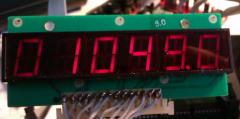
Well I am surprised. It works with a multiplexed display, all 7 segments common. The anodes or cathodes are connected to SR2 7 through 2 (these read right to left so digit 1 is on the right and is the decimal place for the BPM). This saves an extra DOUT for the track position display :thumbsup: Here is the relevant part of my HW file: ################################################## # Optional BPM digits ################################################## # set to 1 or 2 to enable the 3 optional BPM digits # 0: BPM digits disabled # 1: BPM digits with common cathode # 2: BPM digits with common anode BPM_DIGITS_ENABLED 1 # define the DOUT shift register to which the segments are connected (0=disabled) BPM_DIGITS_SEGMENTS_SR 1 # define the DOUT SR and pin to which the common pins are connected # we are counting from right to left # Example: 140.5 BPM: (COMMON1 = .5, COMMON2=0., COMMON3=4, COMMON4=1) # SR Pin BPM_DIGITS_COMMON1_PIN 2 7 BPM_DIGITS_COMMON2_PIN 2 6 BPM_DIGITS_COMMON3_PIN 2 5 BPM_DIGITS_COMMON4_PIN 2 4 ################################################## # Optional Step digits ################################################## # set to 1 or 2 to enable the 3 optional STEP digits # 0: STEP digits disabled # 1: STEP digits with common cathode # 2: STEP digits with common anode STEP_DIGITS_ENABLED 1 # define the DOUT shift register to which the segments are connected (0=disabled) STEP_DIGITS_SEGMENTS_SR 1 # define the DOUT SR and pin to which the common pins are connected # we are counting from right to left # Example: Step 123: (COMMON1 = 3, COMMON2=2, COMMON3=1) # SR Pin STEP_DIGITS_COMMON1_PIN 2 3 STEP_DIGITS_COMMON2_PIN 2 2 STEP_DIGITS_COMMON3_PIN 0 0 And here is a photo, step 01 049.0 BPM
-
I am using a 6 digit multiplexed display so I am not sure if it's possible for me. I will give it a try and report back. I can see that there could be a problem with combining the 2 functions on the digit SR but I wont know until I try.
-
You need the DIN module on J8/9 for the encoder as J10 is used by the control surface and the encoder is connected to the external DIN chain. You only need a single shift register on a DINx1. I can't see a reason why you would need 3 digits on the V4L step display. 16 x 4 is 64 steps so 2 should do. The V4 can do > 64 steps so 3 digits are required.
-
Check my thread about it I found that the PDF in the SEQV4 thread showed the digit segments in the reverse order although the commons are correct. I mailed an updated pdf of the DOUTs for the display to TK. I am not sure if it is available yet but I can send a copy to you if you need it. The SR setup is SR1 for the digit segments and SR2 for the commons. You will need the V55b version of the firmware (available in the thread linked above) to make it all work. Hopefully the BPM display will be included in the next release. I used an encoder I had lying about, I think it's a Bournes one. The DIN setup is very straight forward but you need to use SR1 in the HW file. hope that helps. Tim.. If you are using a common DOUT DIN chain beware that the RC1 and RC2 lines need to be separate for the DOUT and DIN respectively. Check the schematic for the LPC core board J8/9. Looking at the connector from the edge of the board, RC1 is rear row right hand side and RC2 is the front row. That had me going for a bit as I had the 2 RC lines connected together so nothing worked.
-
As with everything, you only get what you pay for. The switch on ebay is designed for mains voltage, do you require the switch for mains or DC? If you want a switch for DC e.g. 9Volts, then this switch will work but the lamp will not light. Tim
-
I had a look at maplin's site, they don't do a DPDT illuminated rocker switch that is suitable for low voltage. A lot of rocker switches have a Neon for mains voltage. Check out Rapid at http://www.rapidonline.com/ or Farnell at http://uk.farnell.com/ Rapid have a good range and Farnell are excellent but have a £20 ex vat minimum order value but it is free delivery(and watch out for stock from their Newark depot which has a £15.99 delivery charge). You will have to check the specific switch to see if the illumination is by separate pins. Tim
-
Thanks TK, I look forward to the enhancement.
-
To wire the switch you will need a DPDT type, this will have 2 rows of 3 pins. The centre pin in row 1 will go to your pin 3, the remaining pins, one will go to 1 the other to 4. The centre pin in row 2 will go to your pin 7, the remaining pins, one will go to 5 the other to 8. The wires to your pin 1 and 5 should be next to each other on the switch and the the same for 4 and 8. The bottom of the switch would look like this: 1 3 4 5 7 8 The power supply would probably require about 500mA, that is the maximum load for a USB port, this may be a little too much for an off the shelf midi cable. However, I would give it a try anyway. You can connect it as you describe, just be aware of the correct polarity. Tim.
-
Hi, just pointing this out as I am not sure if it is a bug or not and it might help avoid confusion for others. The BPM display does not behave as expected in slave mode. The V4 manual states "in slave mode SLA will be displayed instead". The set BPM is displayed in all cases. It also does not matter which midi in is used. From my point of view this is no big thing, I am just pleased to be able to set an accurate BPM via the encoder. Tim.
-
Hi, welcome to the forum. Your concept is interesting. The switch on the keyboard, I assume it is of the slide type, a simple 2 way rocker switch (DPDT or double pole double throw) would not give a USB position to turn off the power. It would do what you want according to your diagram. Please watch out for the potential to feed the keyboard electronics with the wrong or too much voltage. If it has an external supply connector for a mains adaptor input then the keyboard probably has its own regulator, but if it only has a USB socket (aside from midi) the it is likely that the keyboard will only work with a 5Volt DC supply. The midi thru box could be made like this one. Although it shows 7404 chips, 7407 or 74ls07 chips are a better bet. When feeding power along a midi cable you will need to be careful with the current consumption of the device you are feeding. Most 5 way din cable use thin wires and these will not carry more than a few hundred milliamps, the voltage is also a limiting factor here. Feeding AC alongside a midi signal could cause interference to the midi data. Hope that helps. Tim
-
Need tips for troubleshooting CS MB6582
gomiboy99 replied to dreamer's topic in Testing/Troubleshooting
The common pin of the resistor network should be in the square pad on the board. It may be worth checking in case you have not done it already. -
I assume that the DOUT is connected to the organ so as to operate that key on the organ, in which case check the wiring. You could supply the DOUT with +5V and 0V without the core connected, this would help narrow down where the fault lies.
-
TK, I have now started on the BPM encoder for the V4L, I wonder if the external DIN is disabled like the DOUT was? I ask because I have assigned SR1 for the encoder and this disables the Tempo button on the V4L. Thanks in advance Ooops, helps if you wire it up right! It works fine. Tim.
-
Peter, well I thought I was doing the right thing by following the PDF. It appears that this is wrong as the display works when the sequence of segment lines is reversed. So the Dot is on D0 through to g on D7. Thanks for your help. The display works 100%. :smile: The next step is the encoder for the BPM function. Thanks TK for modifying the code, will you incorporate this in the next release? Tim
-
Thanks Peter, I was aware of that, I may give it a try later but my priority is the BPM display, followed by the BPM encoder. I am still having problems, I have verified (again) that the display and DOUT are working but I still get unreadable results on the BPM display. I have found SR1 and SR2 are the only settings that give any kind of display and tried both for each set of outputs. But some segments are off and the DP appears on more than one segment. I have read Hawkeye's post about setting SRs 1 below the actual value but there has been a new version since that post so I wonder if this is relevant or perhaps the fix (if any) was also included in the V4L update. Again any help would be much appreciated. Tim
-
It may be worth trying a different PIC in the second core. Or try reprogramming it from scratch.
-
Well, good news and bad news. I am now getting a signal to the DOUT but I think I have damaged my LED display, the digits are missing segments and don't display correctly. The display does change when I vary the tempo so time to find another LED display for more testing.
-
TK, thanks for the very fast response. I will try this as soon as I can. Tim.
-
I have recently completed my Seq V4L and wanted to add the BPM digit and encoder option but cannot get the display to work although it is working with other kit. The LPC board is running the latest Seq V4L. I have the MBSEQ_HW.V4L file in the root of the SD card and have modified the appropriate section: ################################################## # Optional BPM digits ################################################## # set to 1 or 2 to enable the 3 optional BPM digits # 0: BPM digits disabled # 1: BPM digits with common cathode # 2: BPM digits with common anode BPM_DIGITS_ENABLED 1 # define the DOUT shift register to which the segments are connected (0=disabled) BPM_DIGITS_SEGMENTS_SR 9 # define the DOUT SR and pin to which the common pins are connected # we are counting from right to left # Example: 140.5 BPM: (COMMON1 = .5, COMMON2=0., COMMON3=4, COMMON4=1) # SR Pin BPM_DIGITS_COMMON1_PIN 10 7 BPM_DIGITS_COMMON2_PIN 10 6 BPM_DIGITS_COMMON3_PIN 10 5 BPM_DIGITS_COMMON4_PIN 10 4 The problem I have is that whatever shift registers I assign for the segments and commons, I get nothing on the display and there is just a logic 0 on the SO pin on the DOUT. I have signals on RC and SC and all wiring is ok from the LPC core. The DOUT is a known working module and the display is fully functional and wired correctly. I have tried shift registers from 1 to 16 in various combinations but nothing works. Using 1 to 8 causes the LEDs on the control surface to act strangely because they are assigned to those shift registers. I have spent a lot of time tracing signals back to the LPC board and everything seems to be in order. I have even swapped all of the ICs associated with J8/9 and the DOUT and still no change. I don't think I have missed anything, read the documentation several times and it looks to me like it should work - even the docs say so. Any help would be greatly appreciated. Tim.
-
I have spent a lot of time trying to get the BPM digits to work but without success, I won't post here but I will open a new troubleshooting thread. Thanks to TK and Hawkeye the issue is now solved.
-
Where to buy 0.1 inch (2.54 mm) pitch ribbon cable?
gomiboy99 replied to Sauraen's topic in Parts Questions
It is not cheap here in the UK, although the prices are for 100 feet. It may give you a clue as to what to search for. http://www.toby.co.uk/content/catalogue/products.aspx?series=L04a-xx-PABB-100F -
Has anyone successfully added the BPM digits to the V4L?
-
Need tips for troubleshooting CS MB6582
gomiboy99 replied to dreamer's topic in Testing/Troubleshooting
595s are for outs and 165s are for ins. Make sure that all of the diodes are the right way round. -
Have you checked for solder bridges with a magnifying glass or continuity tester?