Leaderboard


Popular Content
Showing content with the highest reputation since 01/27/2025 in all areas
-
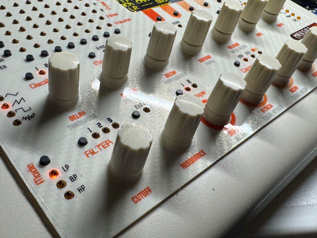
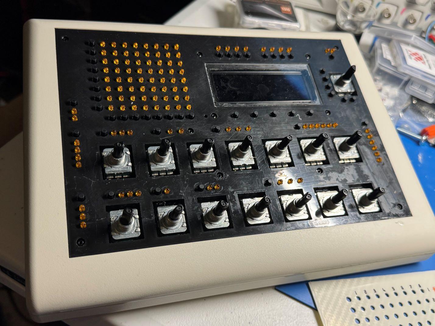
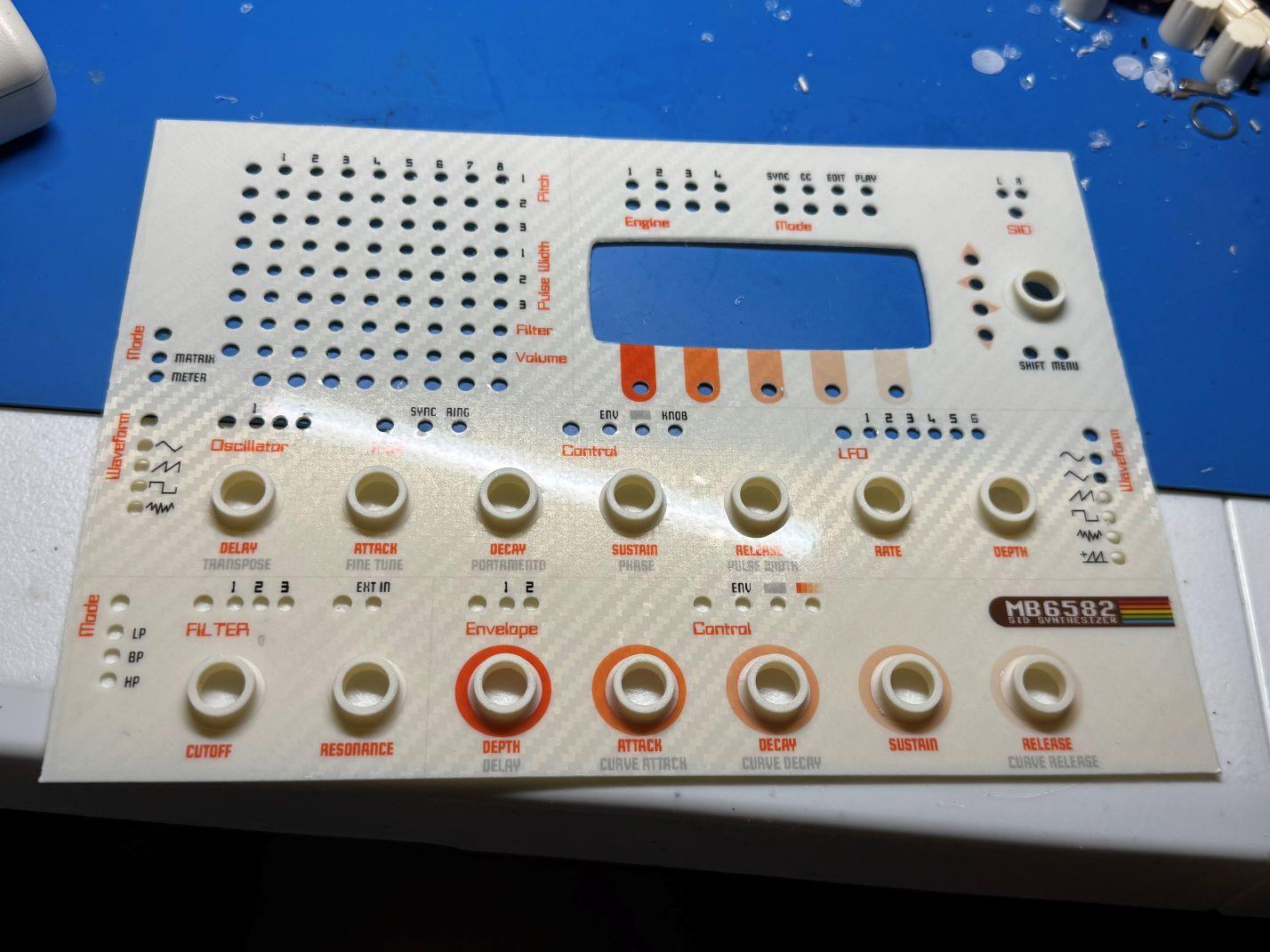
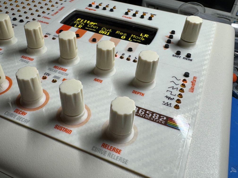
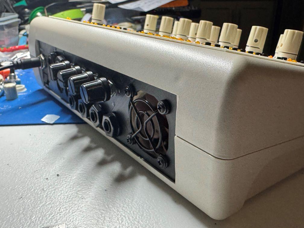
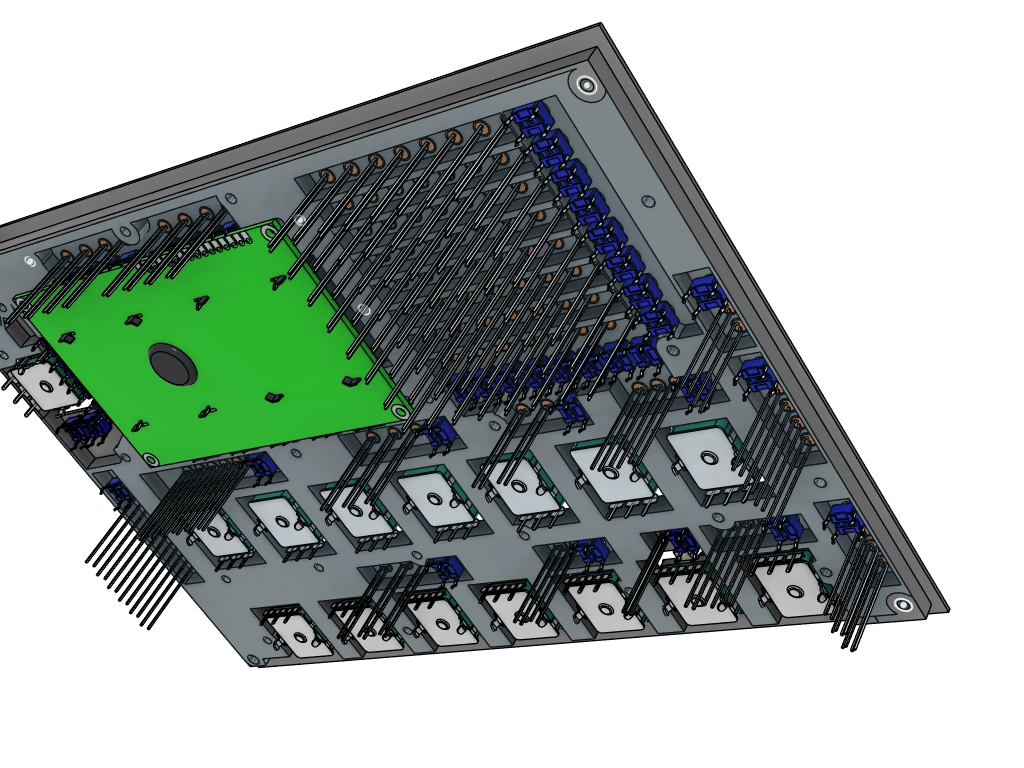
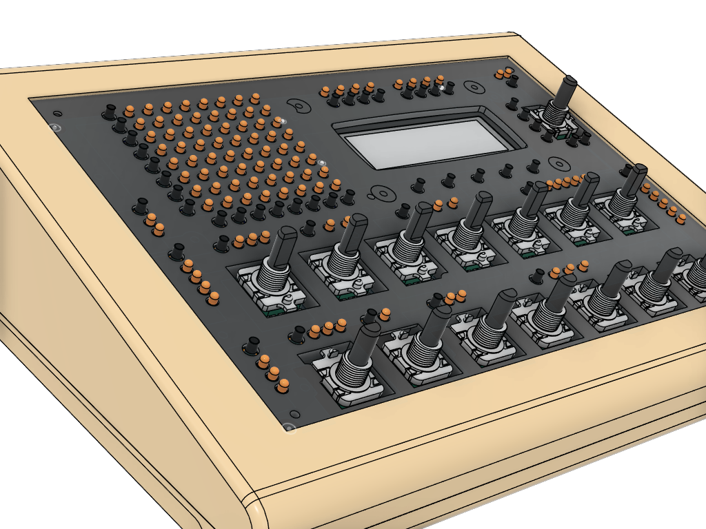
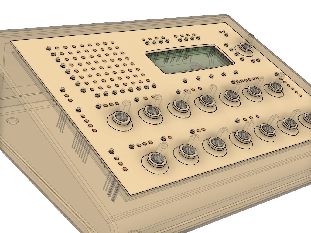
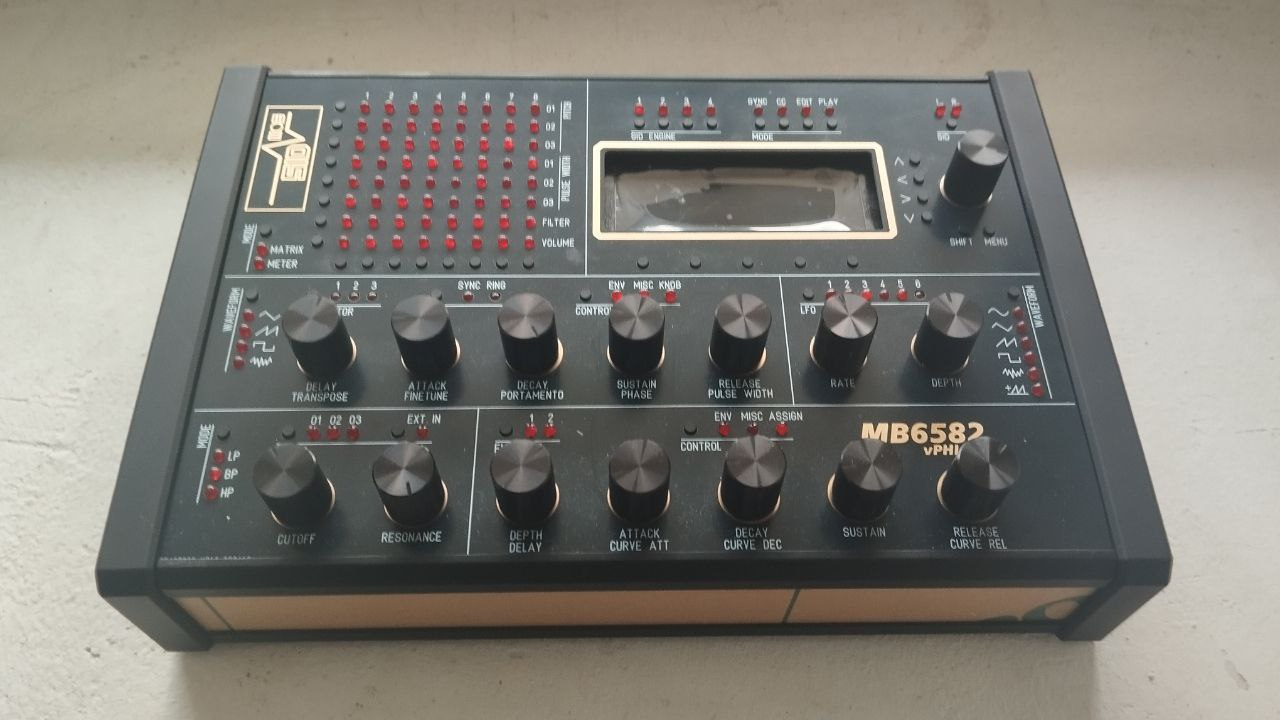
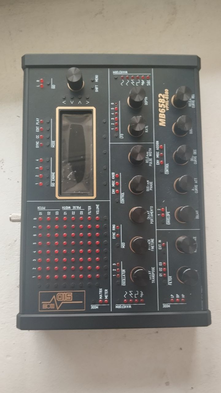
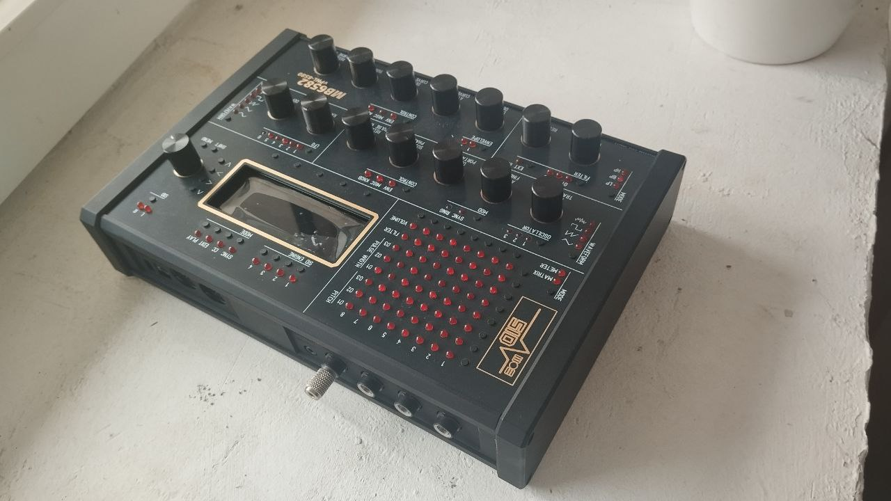
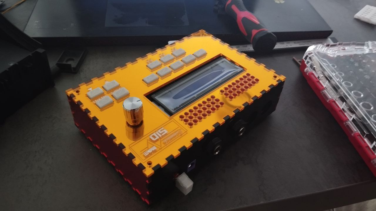
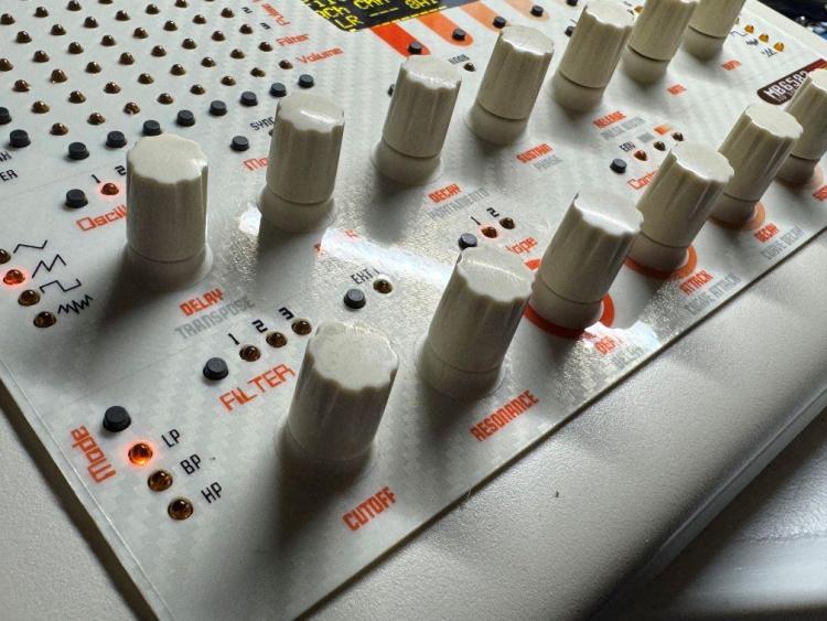
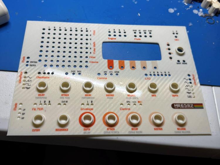
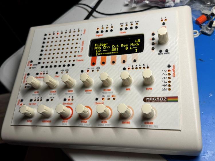
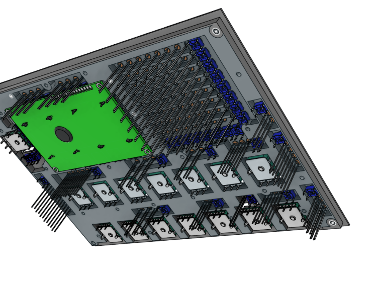
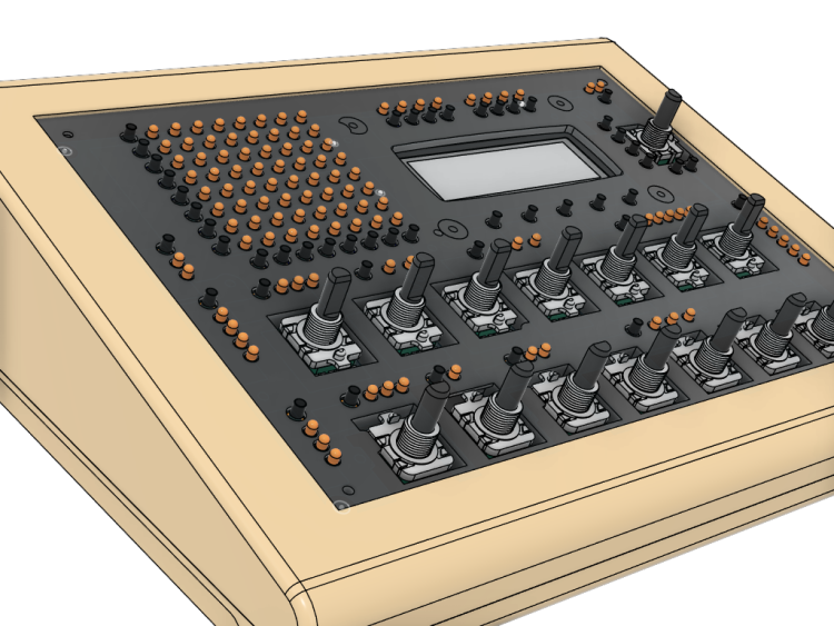
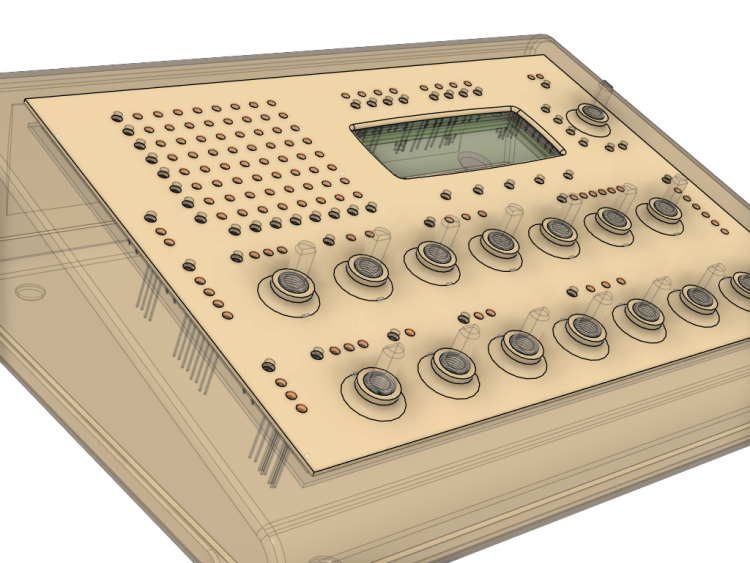
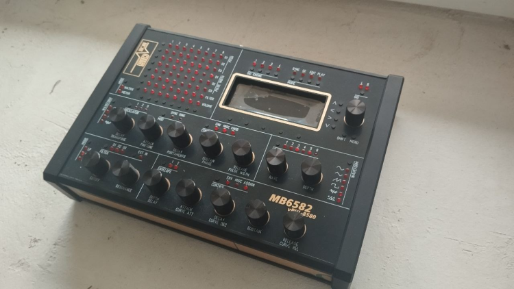
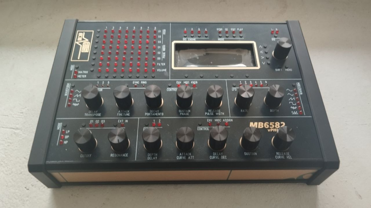
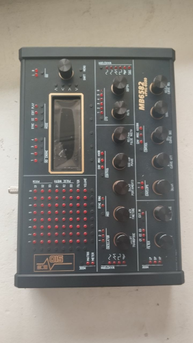
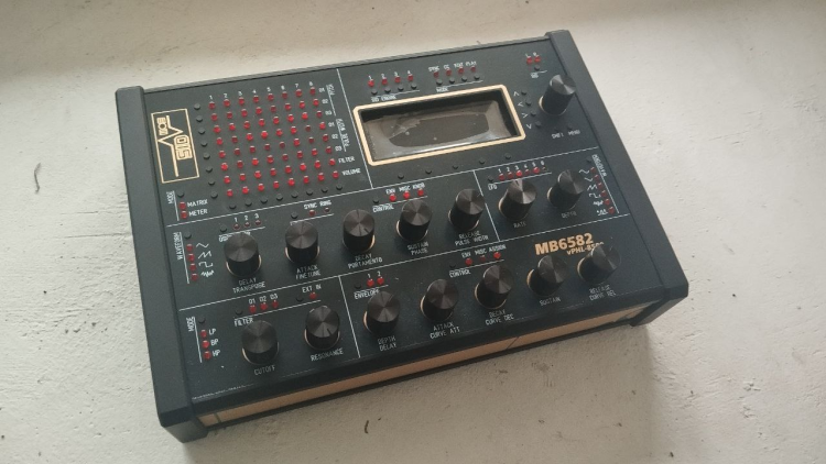
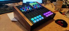
Hey everyone, just wanted to share my latest build since I'm sure there are some 3D printing enthusiasts here like myself. I bought the parts for an MB6582 about 5 years ago, if you remember Meeblip was selling those 8580 SID chips and I picked up 8 of them, and then put everything into a box in a closet . 3D printing has come a very long way since the original MB6582 was created by Wilba. I read that the JB Weld solution may or may not be holding up great after all this time. Also, I wanted to use a Newhaven OLED which is much thinner than the original LCD. I thought there must be a solution to lower the gap distance so why not create some type of spacer for between the front panel and the PCB? I designed all parts in Fusion360. The PCB screws directly into the spacer using M2.5 nuts/screws and plastic screws. The top of it has a flange that rests in the panel groove for the PT-10. Total spacer height is 5.7mm which is the height of the base of the encoders. The front panel is another 1.25mm. Everything is printed out of ASA, which is very strong and heat resistant. I designed the panel graphics in Inkscape and printed on translucent vinyl. I used Davies knobs with small printed skirts to cover up the threads of the encoders since they were exposed. I do not have a vinyl autocutter but I do have an exacto and lots of patience Overall tried going with a 80s beige computer look. A build plate for my printer created the carbon fiber effect on the panel. I'm happy to share the 3D files if anyone could use them.


 3 points
 -
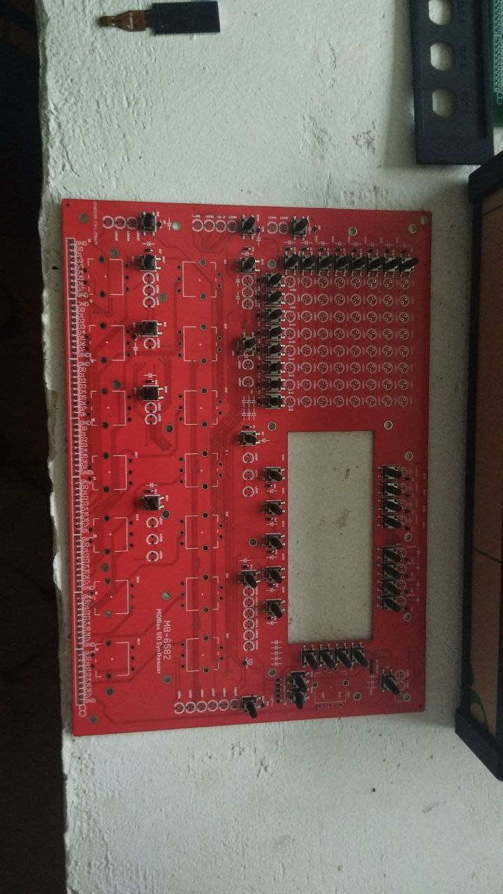
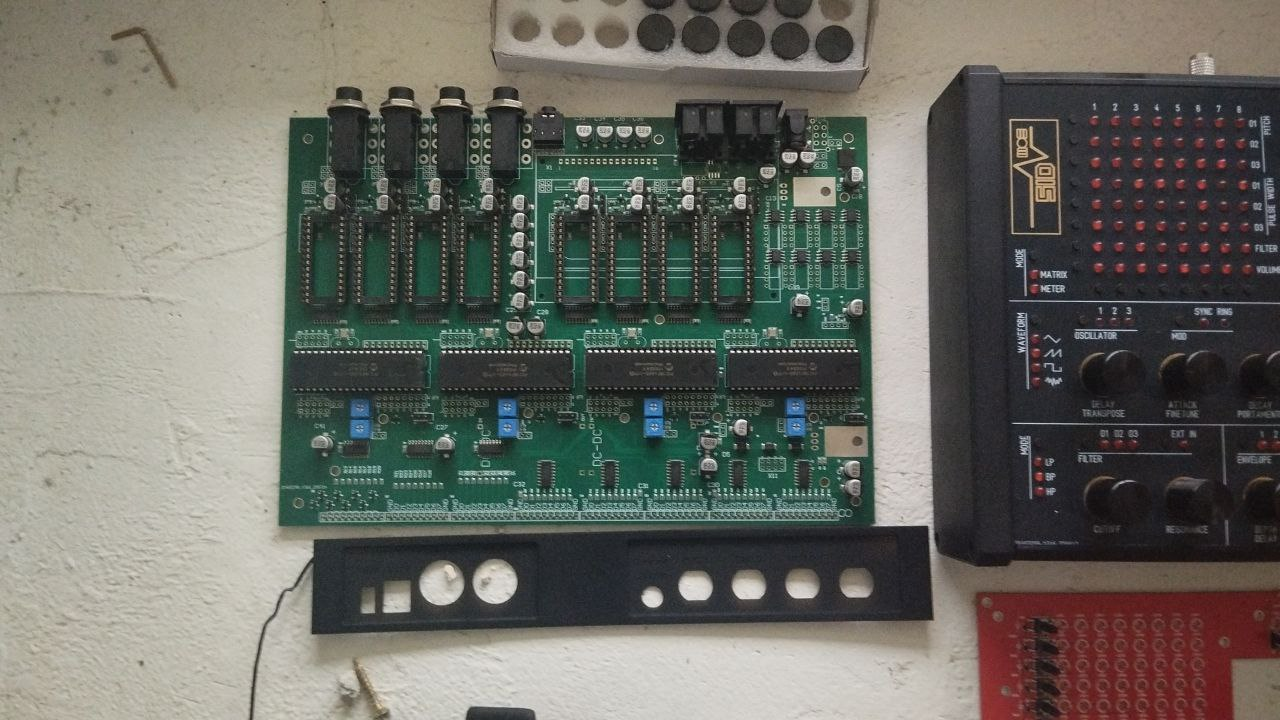
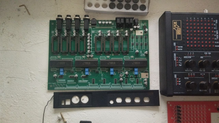
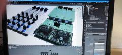
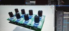
Hello everyone! Over the past few months, I’ve engineered a brand-new MB6582-style synthesizer, deeply inspired by the original Midibox MB6582 but redesigned completely from scratch for improved reliability, easier assembly, and modern component availability. Key new features: Premium ENIG front panel PCB - durable, professional finish 4 PIC cores onboard - full MB6582-compatible architecture Factory-manufactured PCB set, including the front panel Supports ArmSID, Kung Fu SID, or original 6581/6582/8580 chips Clean internal layout, solid build, and high-quality components Prices: Base unit: 420 EUR + shipping With Kung Fu SID set: 499 EUR ArmSID pricing available upon request. Availability: The license allows producing 10 units, so I’m offering 9 units for sale. 1 unit is in stock right now Additional units can be assembled in 3-4 weeks If I receive permission to sell more broadly, I plan to lower the price and release all design files as open source I will make a separate thread in Latest News or somewhere else Photos PCBs and components:


 1 point
 -
From the album: S.M.A.K.
MBSID-6582 NES gray colour scheme with flat headed yellow LEDs and Caps from Elektron. Pac-Tec 10 Case1 point -
Thanks for keeping this projects alive I will try to buy one of them next month if its possible again thanks so much for your work Best regards1 point
-
Hello how much will cost the mb6582? and also If you plan to build a sammichFM let me know1 point
-
Hi! Answered in PM. Yes, sammichFM can be ordered by dropshipping. Only a bare PCB can be ordered currently. Also coming soon - a new MB6582-compatible synth Inexpensive, fully compatible, affordable, technology optimized Will make a new thread soon
 1 point
 -
Apologies everyone I just saw these messages. I will make a note of gathering the files tonight and uploading them to the appropriate section here (Thanks Smithy). Thanks everyone for the kind words :)1 point
-
From what I gather from the manual and changelog, this LED indicates whether you have selected a „positive values only“ waveform for the LFO (instead of applying the default workaround by showing waveform LED + Random LED). It does not indicate that the value of the LFO is currently positive.1 point
-
1 point
-
Prompted by a message from freddy, I've attached the project files below. They contain the source and the binaries for the bootloader and the main code. 1.05 is the latest version - there was a fix in the bootloader and the main code. I included some memory in the final hardware design but never got around to doing anything useful with it. I had plans to save one or more demo tunes as MIDI files and perhaps save some settings as profiles for different scenarios - my interests had moved on before that happened. You can find more project info at https://web.archive.org/web/20210206041027/http://www.grapevyne.com/pic.projects/ - the documentation links are all active so you can download the magazine articles and also my original source for the articles (a few errors crept into the magazine article during editing). mistralXG project files.zip mistralBoot.zip1 point
-
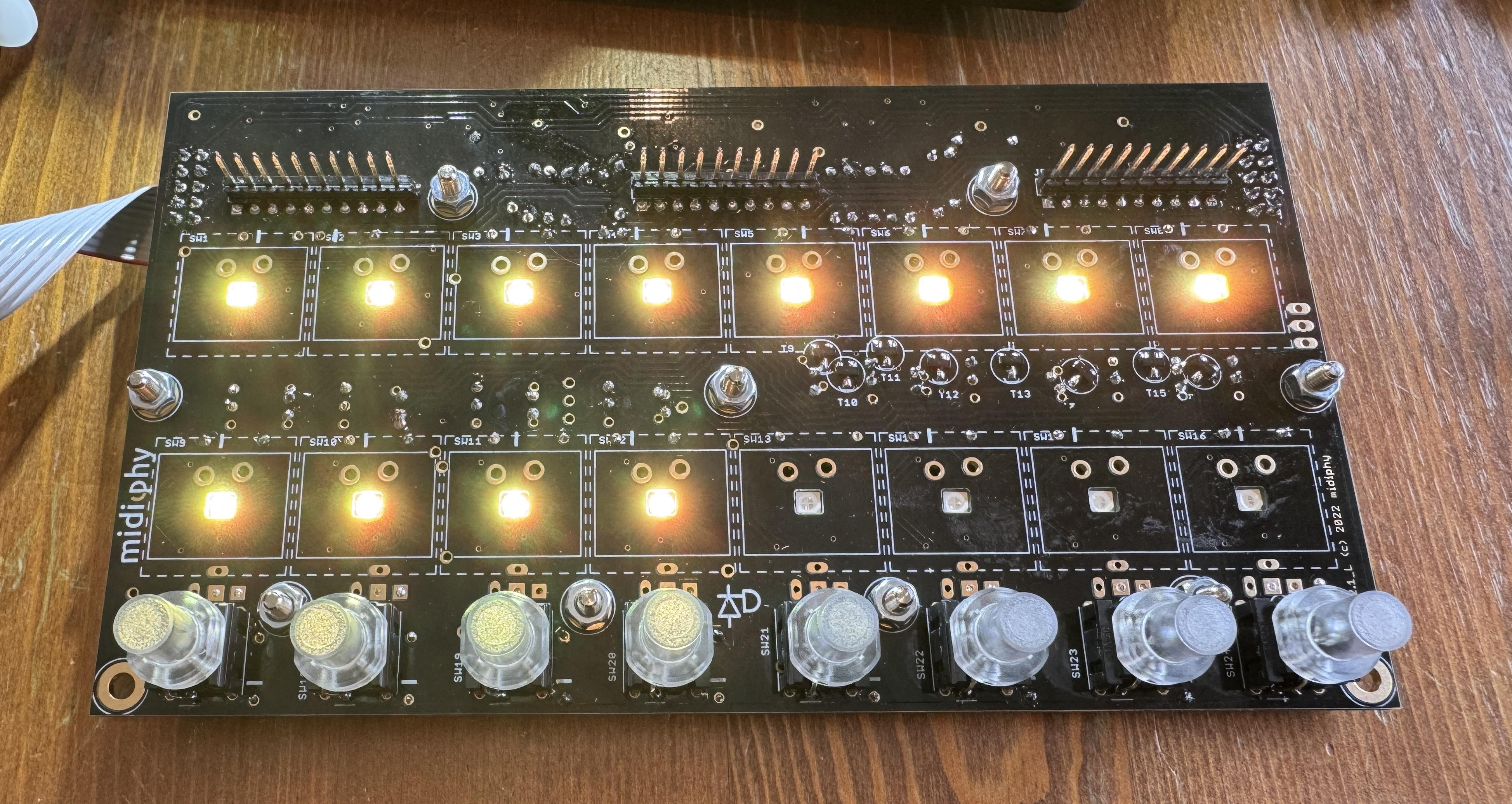
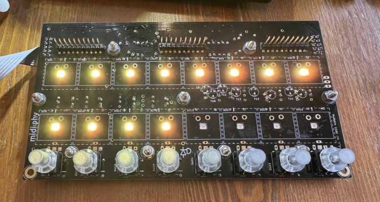
Hi all I am having a very hard time making any progress with a problem with my left LeMec board. When I first assembled the JA and LeMec boards and tested them, everything was working on JA board and the two LeMec boards except: - encoder 3 on left Lemec board was not registering depress events - encoder 8 on left LeMec board was generating garbage counter values when rotating. Since then I have gone backwards and been stuck for over several weeks with no progress. I first tried to solve the issues above with reflowing the ICs on left LeMec board but that didn't help. I then reflowed the ICs on the core, and after that, I am in this worse state with left LeMec board - encoder 8 does not register turns - none of the encoders are registering push events - 4 leftmost buttons on are not registering push events - 12 of the 16 LEDs light up immediately upon powering up as seen in attached pic I haven't bothered testing the Matias switch events as this is enough wrong already I have reflowed the ICs, diodes and transistors on that board multiple times, and on the core board too, and nothing is changing. The only advice I get from Midiphy is to reflow/check for dry joints/shorts which I have done over and over. It would help to have proper circuit diagrams to try to chase down likely culprits instead of messing with everything all the time. If I just connect the JA board to core and run the seq_l test, that is still testing fine for everything. The right LeMec board is out of the picture for now; I think it was all working well at least. Any help will be most welcome as I am close to assuming I just have to abandon this and write it off as a very expensive exercise in frustration and futility. Thanks Graham
 1 point
 -
To use Studio on newer Ubuntu Desktops you need to install the old libwebkit2gtk-4.0.so.37. To do so create a sources.list file for apt containing the following line: deb http://gb.archive.ubuntu.com/ubuntu jammy main And install the lib. sudo apt update sudo apt install libwebkit2gtk-4.0-dev After this delete the sources.list file. More infos on https://www.weigu.lu/music/midibox_hp_2x2/index.html1 point
-
II replaces the remaining ICs and its working! Woohoo!1 point
-
Reflowed the ttasnsistors on the top side and now I am back to 12 LEDs on. I'm assuming the LEDs shouldn't be on, but otherwise that feels like an improvement as it means I get mattias switch events for 12 of 16. I'm also getting events for depresses on the right 4 encoders although they seem a bit random in the actual event details. I've also replaced IC2, IC3 and T3 based on advice from ChatGPT but that made no difference.1 point
-
Thanks, perhaps I'll shoot over to the UK ;-) I've rebuilt the core board now and I'm back where roughly where I started. At least I feel confident I have eliminated the core as a possible cause; the problem must be with my LeMec board. Done some more reflowing on that board and now: - just 4 LEDs light up on power up now - all encoders generate counts when rotated but not depresses - botton left 4 buttons generate no events; bottom right four are working - mattias switches generate events for the four that have illuminated LEDs but not the rest1 point
-
This looks amazing! With some of the older chips like vintage vca, filter or delay chips you really have to be careful regarding heat and also (or even more so) static discharge. Nowadays with most ics these issues have long been solved by modern manufacturing processes and built in safety measures. I had to lear the hard way that this is not the case with chips from the 80s... So the heatsink is probably a good idea, as would be any way to allow for some airflow. On the other hand, i have removed the fans from some of my gear with no issues at all, as commercial units have to consider every worst case scenario (crowded rack in hot environment). So if you know how you use your gear you can get away with things that could not be allowed for every scenario.1 point
-
Cool solution, looks great! The skirts for the knobs are a nice touch. One thing I wonder about is if heat would build up here, as the free air space in the case is less and the panel is also an insulator. The SIDs are on another PCB of course.1 point
-
With velocity bars there is more info displayed and the spacing is more uniform. The hyphen/minus as a spacer for natural notes helps to connect them; with spaces it is more confusing. Do you really use those low octaves so often @anonyme-x22? If it bothers you, a workaround is to transpose either on the SEQ or your synth.1 point
-
Hello, When i mute part, i can do it by bottom row (normal known behavior), but also the top row. So it's confusing. Being able to mute only on bottom row will make the workflow more consistant. Or it could also being interesting to be able to mute differently between upper and bottom row. Like top row track 1-16 mute. Bottom row group 1-4 mute. Thanks in advance, Have a good day, Rgds,1 point
-
MB-6582 SOLD Selling these as I no longer use them. I assembled the MB-6582 myself. It has 6x 8580 SIDs installed, and could use some TLC: - The encoders occasionally skip counts when adjusting them. I think this is just down to a bad batch so replacing them should fix it - Some of the standoffs that attach the front panel to the CS PCB have come unstuck and need to be reglued The SEQ V4 works perfectly €500 for either unit I am based in Spain
 1 point
 -
Hi Niles, I still have original mb6582 encoders, bulk ordered and sent by Wilba. Working perfectly! Would you like some? Best1 point
-
Arrived and kicking. Thank u for your service ❤️1 point
-
Confirmed over here, no humanizer being applied to CC’s. I tried with an empty track sending layer A as CC on buss 1, and another track listing to buss 1. The listening track was responding to the cc’s, but humanizer did not effect the CC’s. Then moved the cc to layer B (usually the velocity layer) and still no changing of CC’s sent. steve1 point
-
New top as requested PM me please, or I can send the details as well.

 1 point
 -
From the album: ModulBox Ng V2
1 point -
From the album: ModulBox Ng V2
1 point -
From the album: ModulBox Ng V2
1 point -
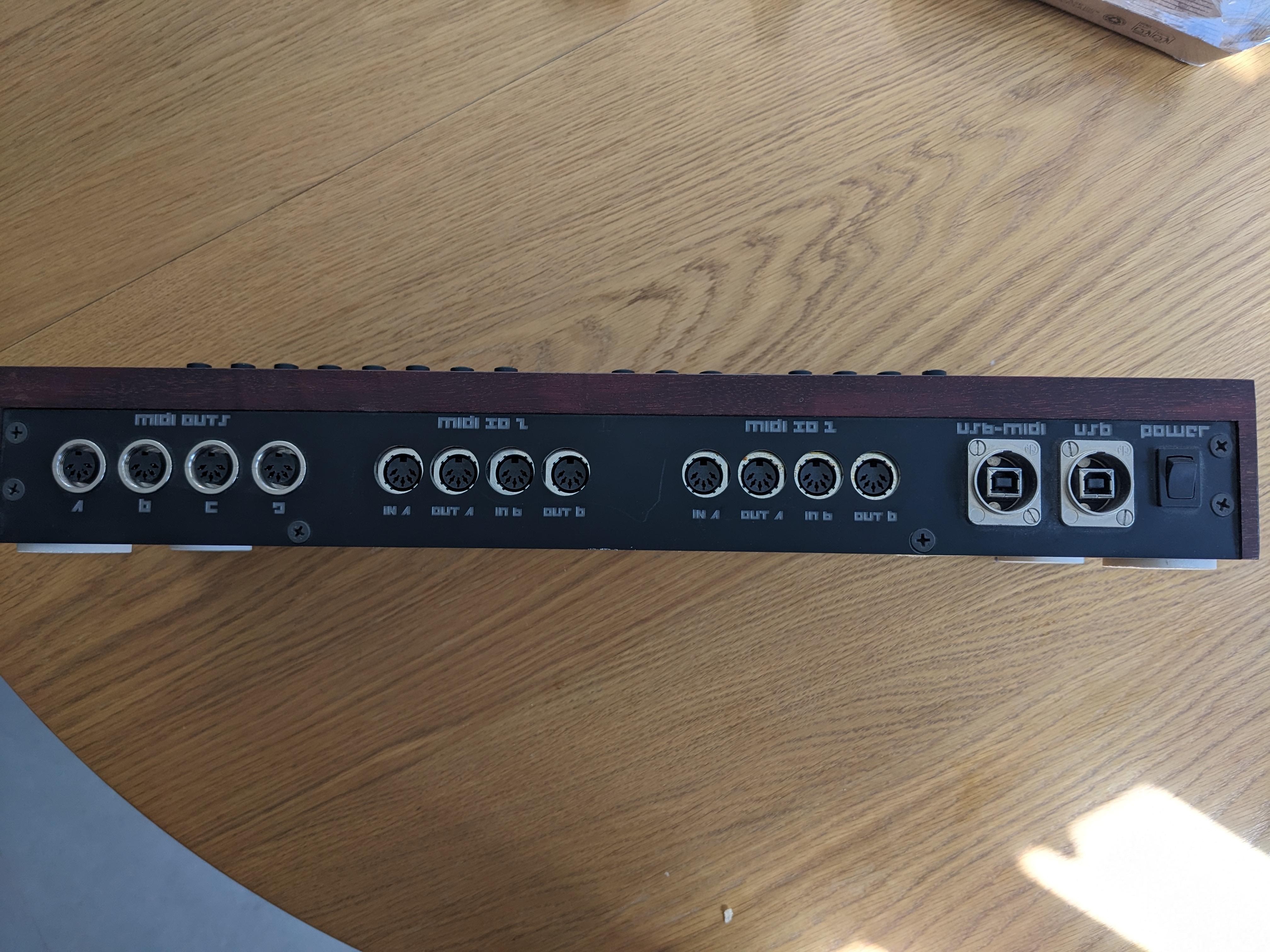
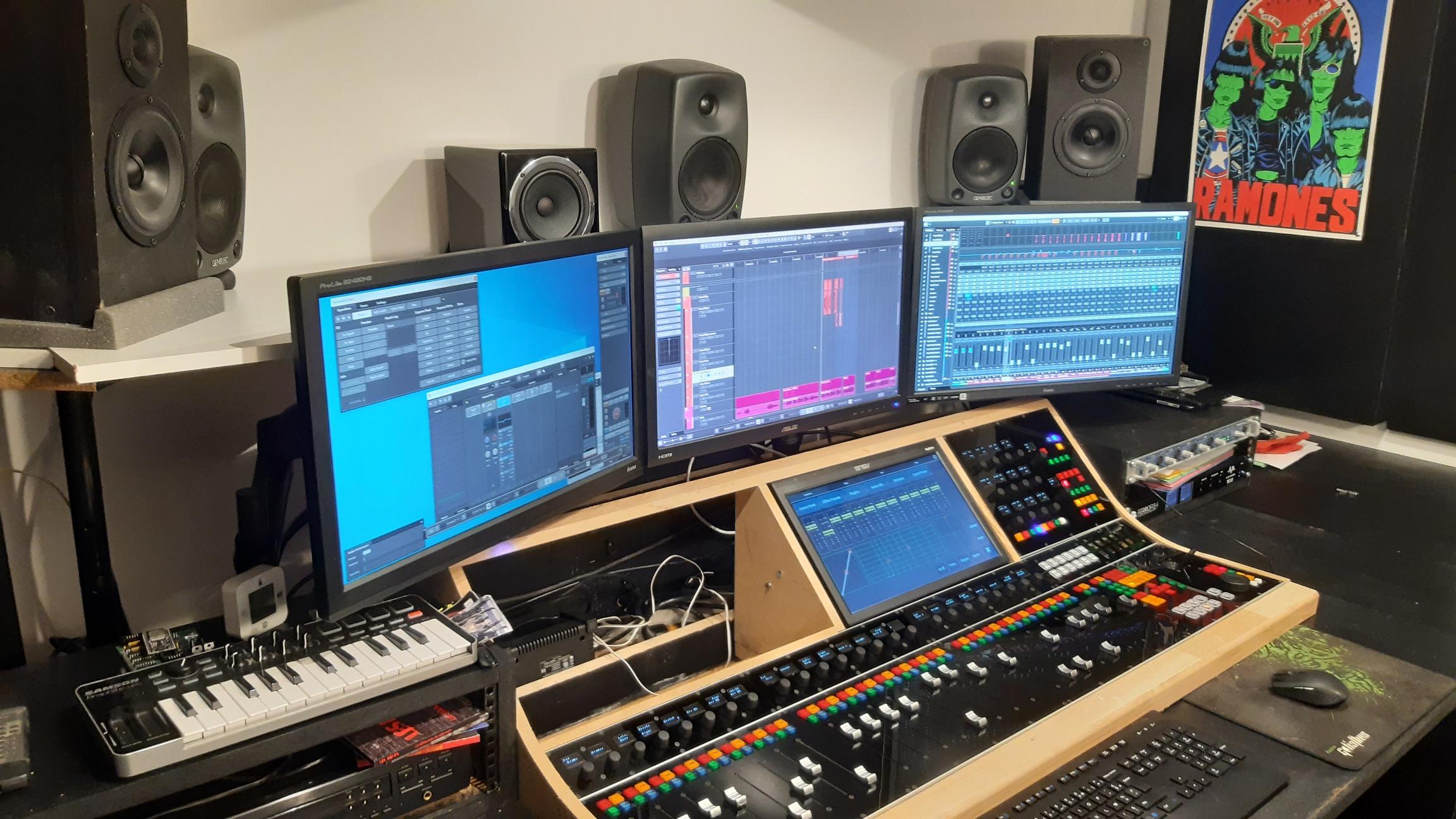
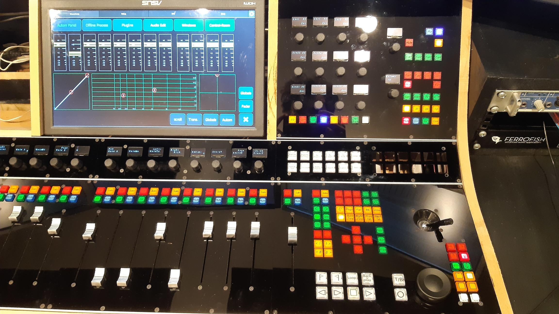
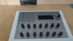
Hi everyone! Quick update here. I finally finished my controller and installed it in my small control-room. Here it is. I really like the way it turned out, i'm working with it since 2 weeks now, and it's a real bonus to the ergonomics. It still have room for improvements but that was expected and i will continue to work on it in the next future. I'd like to thank everyone on this forum who helped me build this and a BIG thanks to TK and all the midibox team. Without this place I would have never been able to even start this project. Cheers, Thomas

 1 point
 -
Good. Maybe someone need good midi samples for beatmaking www.lucidsamples.com/edm-samples-packs/278-edm-magical-midis-vol-3.html and https://www.loopmasters.com/search?q=midi1 point
-
for those who don't find a sd card socket for the core stm32F4. you could use micro SD card and the ADAPTATOR will be the socket like:http://www.ucapps.de/mbhp_sdcard.html first solder unused component legs to the adaptator: solder to the core but leave some space to the board for avoid short (be carefull pinning): you could fix it (glue) if you want (not done for me legs are sufficiant) et voila!1 point