FantomXR
-
Posts
1,035 -
Joined
-
Last visited
-
Days Won
22
Content Type
Profiles
Forums
Blogs
Gallery
Everything posted by FantomXR
-
No, I don't use that. Hm... strange. At least the LED rings do not update. I didn't doublecheck with the controllers itself. I'll investigate .... Thanks for adding the load command!! ;-)
-
Hm... I can try that. I think I tried already something like this. I ran into a problem, that some controllers have range=mapx and RECEIVERS don't seem to support ranges. Anyway: I'll give it a try again.
-
Hey people, I have a question regarding banks: I have my workstation set up with different banks (see the other thread Story of keyboard build). The idea was, to assign the banks to different controllers in my live-host on my computer. So f.e. the first bank controls the volumes, the second bank controls the drawbars, etc. Now it's the case, that every patch in my live-host contains different settings for drawbars and volumes of course and when I select this patch all these values are send out by the live-host to the MIDIbox. The "problem" is that the MIDIbox only listens to that bank, that is selected and the other banks do not change their values. Is there a workaround for that so that the MIDIbox listens on all banks for value-changes? Thanks, Chris
-
Dear TK, sure! It's not a problem now calling it manually :-) But I have another question: I have some LED-rings here and I'd like to use one of these LEDs as status-LED for the switch of the encoder. I configured the encoder like this: EVENT_ENC id=1 fwd_id=LED_MATRIX:8 type=NRPN chn= 1 nrpn=301 range= 0:127 led_matrix_pattern=1 And the switch like this: EVENT_BUTTON id=101 hw_id=32 fwd_id=LED:1127 radio_group=1 button_mode=OnOnly range=1:1 The switch itself is working but as soon as I move the encoder the switch-LED goes off. I thought it has something to do with the led-matrix-pattern. But as you can see the last LED is not adressed here: LED_MATRIX_PATTERN n= 1 pos= 0 pattern=0100000000000000 LED_MATRIX_PATTERN n= 1 pos= 1 pattern=1100000000000000 LED_MATRIX_PATTERN n= 1 pos= 2 pattern=1101000000000000 LED_MATRIX_PATTERN n= 1 pos= 3 pattern=1111000000000000 LED_MATRIX_PATTERN n= 1 pos= 4 pattern=1111010000000000 LED_MATRIX_PATTERN n= 1 pos= 5 pattern=1111110000000000 LED_MATRIX_PATTERN n= 1 pos= 6 pattern=1111110100000000 LED_MATRIX_PATTERN n= 1 pos= 7 pattern=1111111100000000 LED_MATRIX_PATTERN n= 1 pos= 8 pattern=1111111101000000 LED_MATRIX_PATTERN n= 1 pos= 9 pattern=1111111111000000 LED_MATRIX_PATTERN n= 1 pos=10 pattern=1111111111010000 LED_MATRIX_PATTERN n= 1 pos=11 pattern=1111111111110000 LED_MATRIX_PATTERN n= 1 pos=12 pattern=1111111111110100 LED_MATRIX_PATTERN n= 1 pos=13 pattern=1111111111111100 LED_MATRIX_PATTERN n= 1 pos=14 pattern=1111111111111101 LED_MATRIX_PATTERN n= 1 pos=15 pattern=1111111111111101 Do you know what I'm doing wrong?
-
Ah okay! Is it possible to load another NGC by pressing a button? :) The reason why I ask: I now had a few times the strange behaviour that my default.ngc was partly overwritten by the "stock" default.ngc, that MIOS installs when no default.ngc is available. I don't know where that comes from. Using another NGC is just a workaround.
-
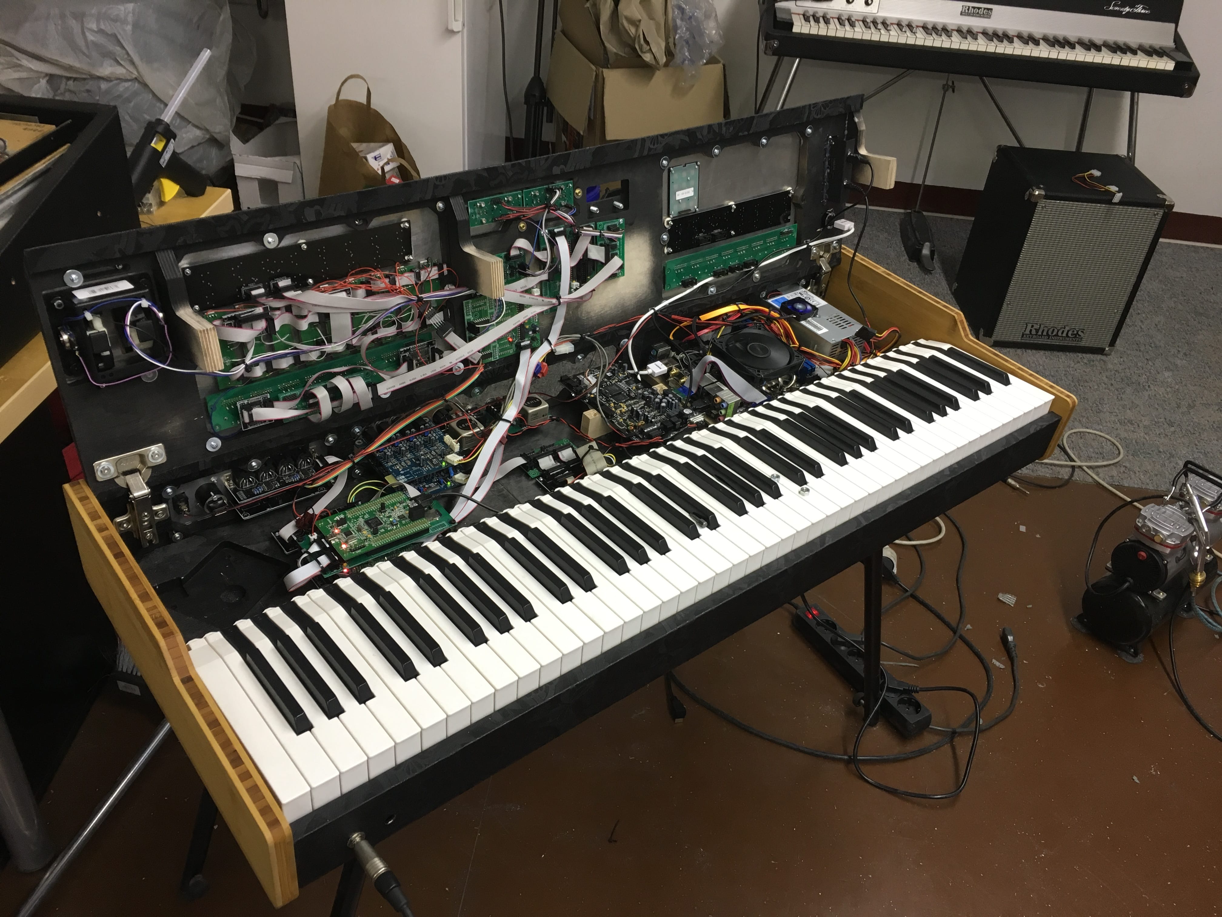
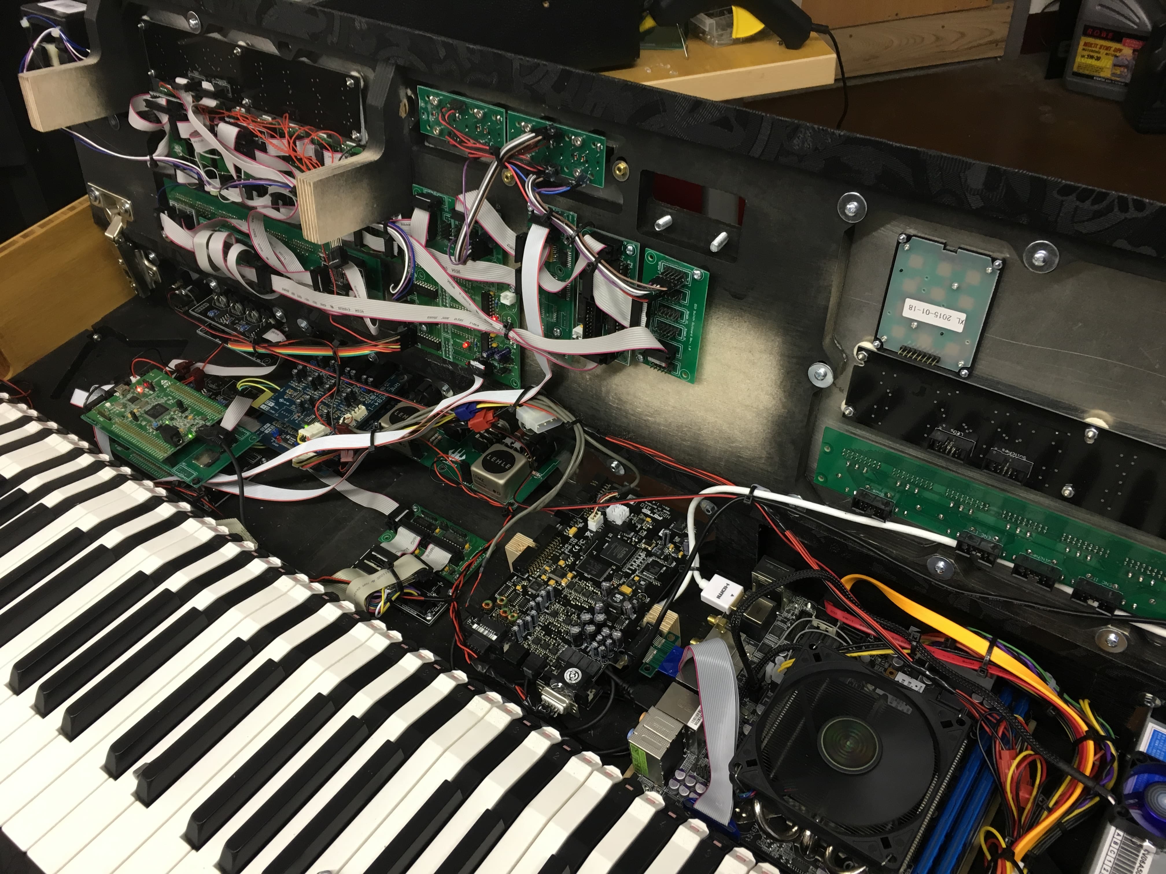
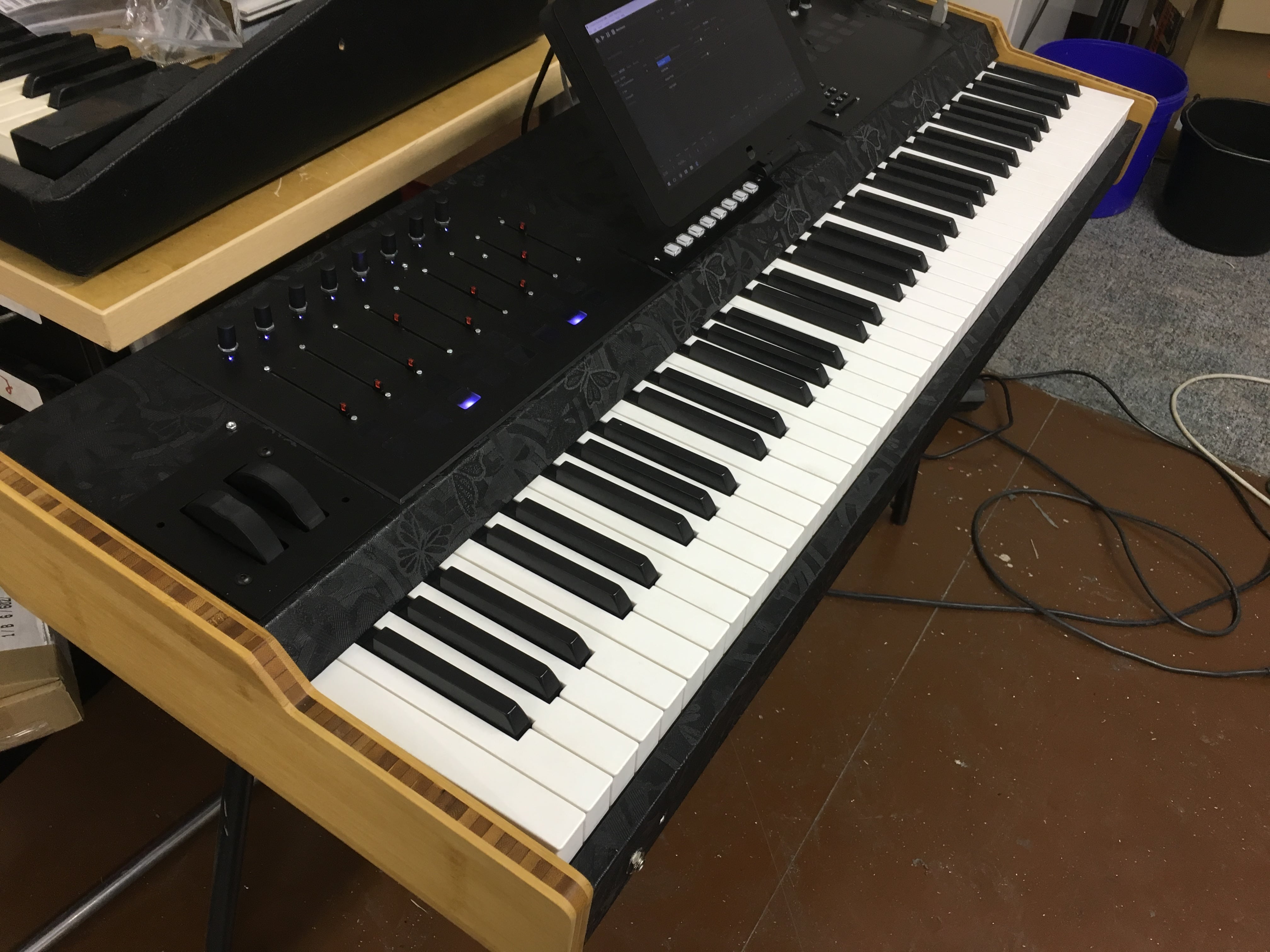
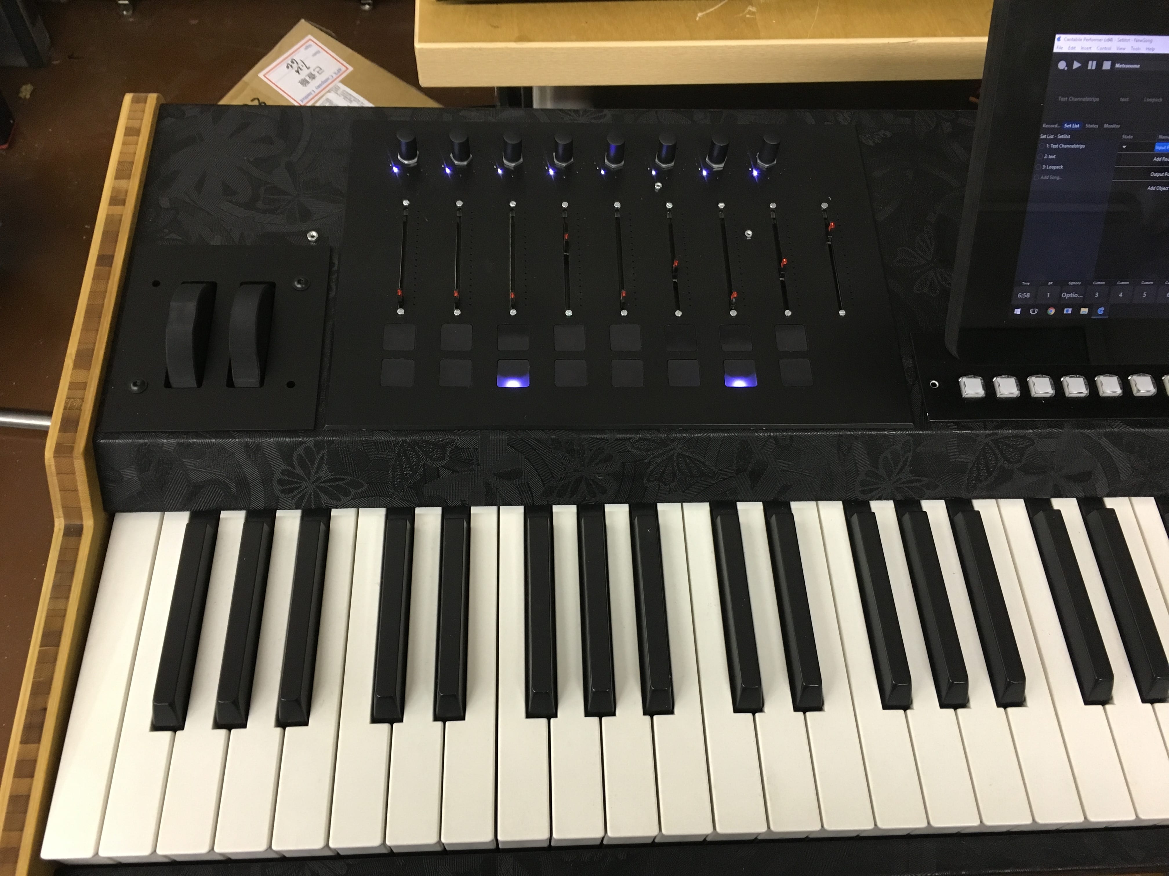
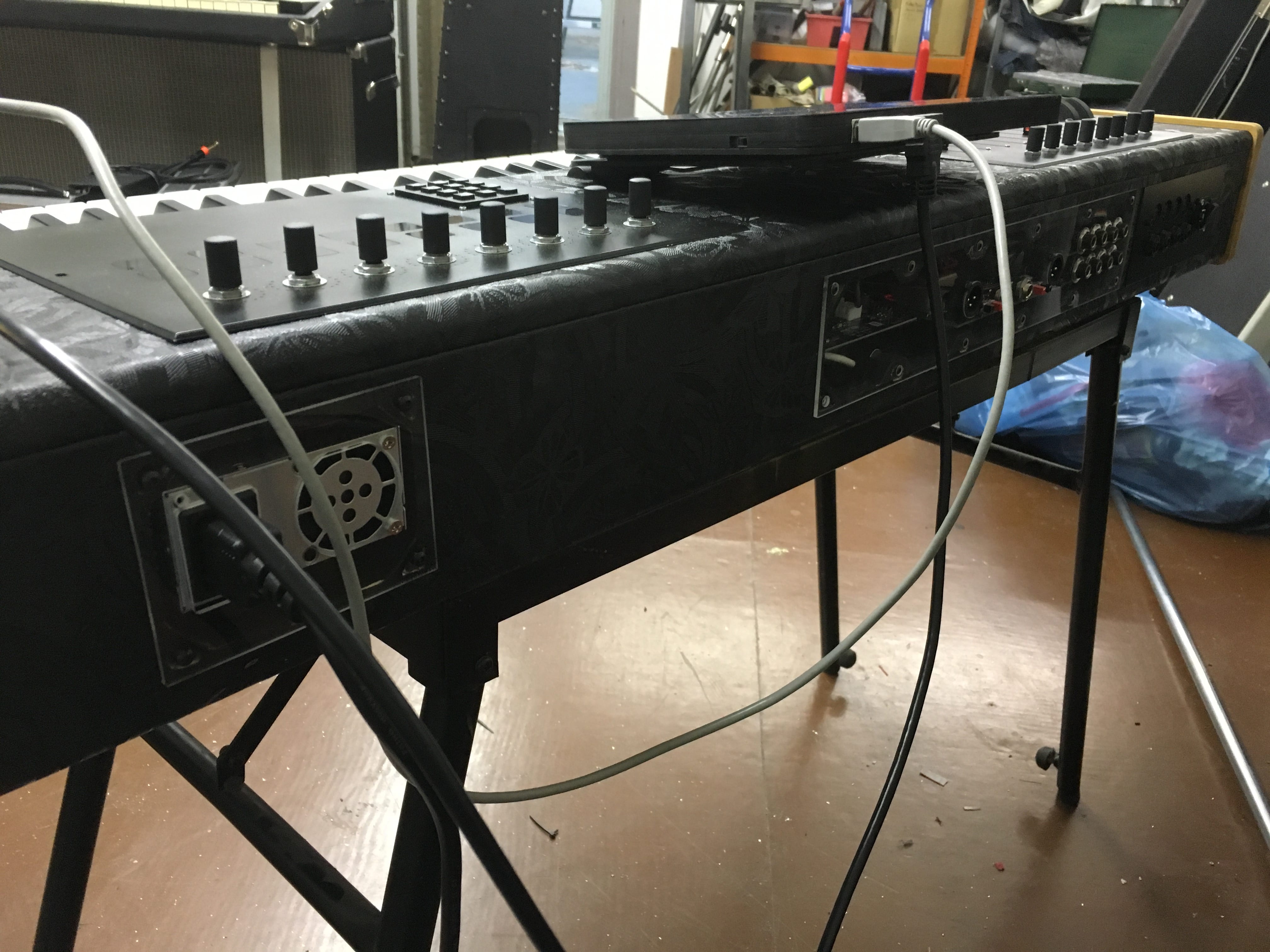
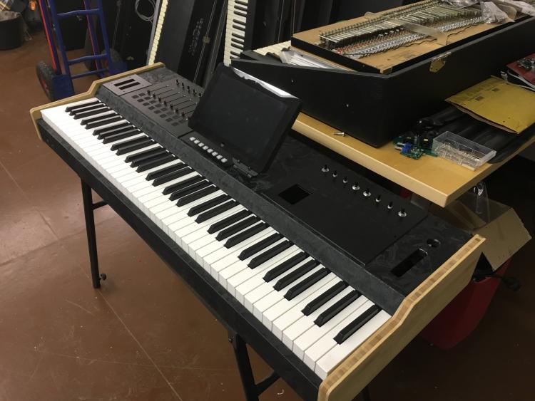
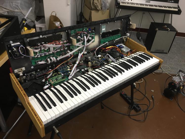
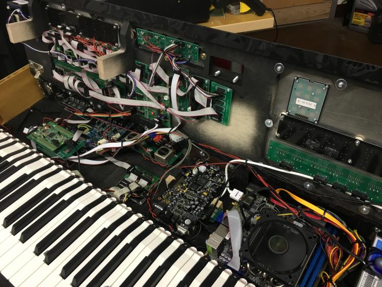
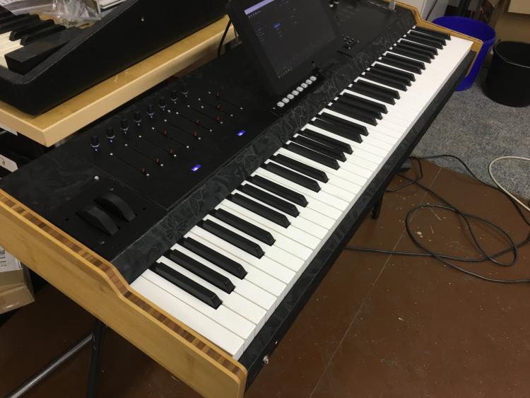
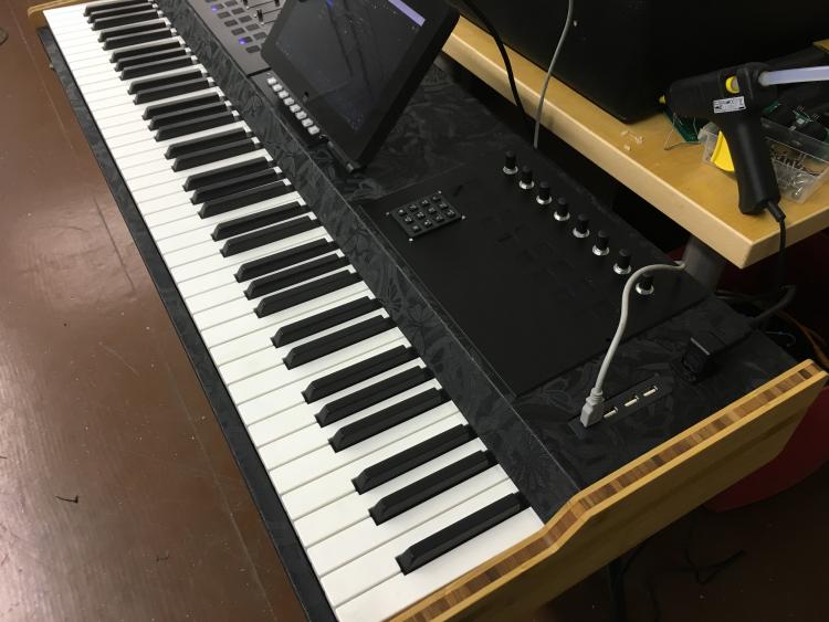
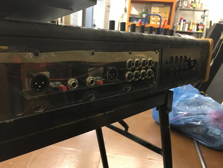
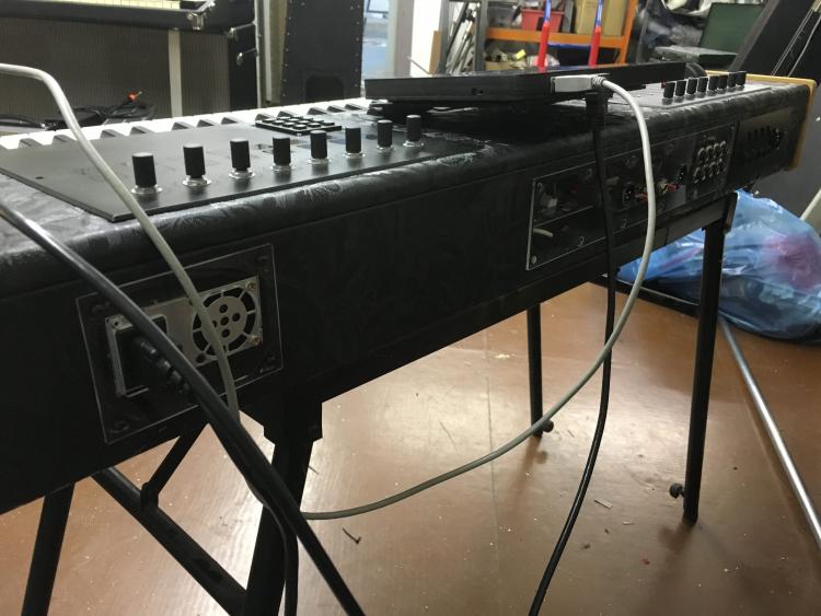
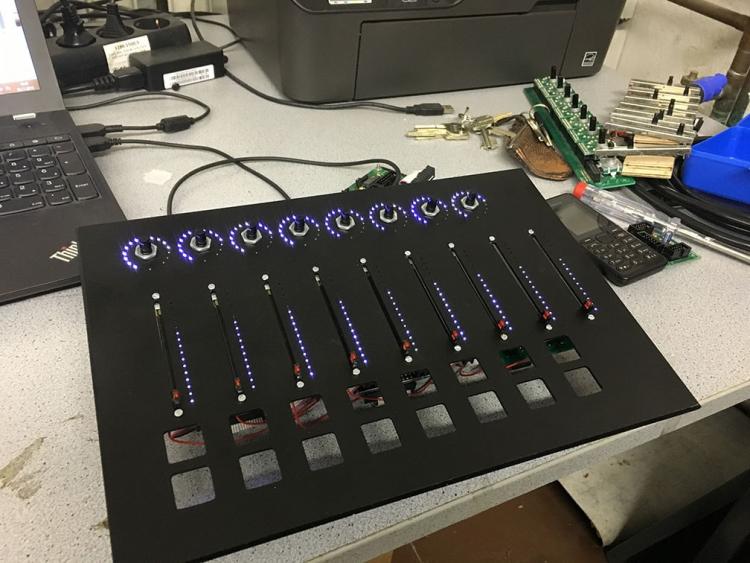
Hey people, in this thread I'll post time after time updates about my latest keyboard build. Also I'll use this thread to publish eagle-PCB-layout-files and schematics. But please be patient. Uploading and documenting all that stuff is highly time consuming and it's right before christmas. So far everything works great, but the work under the hood was really time consuming because I used a lot of modules... some available from Tim, some I did on my own. I think modules are great if you need high flexibility... and all the modules are working perfectly. But if it comes down to save space and wiring, modules are a mess. Anyway... here we go: So I was tired using a laptop, a soundcard, tons of cables and all that stuff on stage. So I thought: What if I put the computer into the keyboard? It was quite successful. I used an Mini-ITX mainboard from Gigabyte, an i5-3570k (I'd go with a better i7 if I hadn't had that i5 before) with a low profile cooler. The mainboard is equipped with 16GB of RAM. Also I integrated two Samsung SSDs with 500GB each. The whole thing is powered through a Seasonic SS250U power supply. As soundcard I use a PCIe card from RME HDSPe AiO. Because this only has two audio in/outs, I also bought two expansion-board that gives me another four in and outs. The first two analog-outs are going through a self-made DI-box with high quality LEHLE-transformer... absolutely great stuff. This DI-box features also a 20dB PAD and a GND-lift. Let's hand over to the MIDIbox-side: I use two cores. One of them only takes care of the keyboard scanning. It was very important to me to not make a compromise on this. This core is connected via MIDI-out to the MIDI-In of the other core. Both cores are STM32F4 based. I used my own PCBs for that. @TK. Is it a problem if I publish those schematics and layouts for the core? I know that the official core is not published yet to cover the costs for PCB production and development. The PCB I developed only contains the connectors I need: it has J8/9, J19, J10A, J11 and J30 (as far as I remember... don't have it right in front of me at the moment). I tried to get a smaller footprint of the whole PCB. It also features a MicroSD-card slot instead of the SD-card-slot in the official PCB. My keyboard has nine analog faders build in... they are not motorized. I don't need that for now as they are much more expensive and also take more space. Also they are more difficult to wire up and connect. At first I did some tests with the AINSER8. But after a while I gave AINSER64 a try with the result, that it has less jitter than the AINSER8. The faders are a lot more quiet than with AINSER8. As I needed more than 16 analog inputs this was needed anyway. I power the AINSER64 through the core and the core receives it's power directly from the seasonic-power supply and NOT via USB. I needed some LEDs to visualize the status of my faders. A long long time ago I wanted to start another LED-fader-project but never finished it. So I had a lot of those LED-bars laying around... I took them and putted them into the board... works and feels great! On the next revision I'd try to use one big PCB for all 9 LED-bars to safe wiring and time for mounting. Now I used two 10pin IDC connectors (with only 8 pins of each are connected to the LED-bars = 16 LEDs). I did some mistakes when assembling the LED-PCBs... now sometimes some LEDs don't work... anyway... I can live with that for now. @TK. How about the WS2812 or APA102-LEDs? Do you think it's worth using them as LED-rings? I'm not sure what the status is and if they are supported in that way by MIDIbox. Would be a great alternative but they take a lot more space than 0603 SMD LEDs of course. The LED-bars are connected to small modules I did based on @novski designs. Those small modules are equipped with one or two DIN / DOUT modules. They work great and the advantage is, that I can stack them directly on the pinheader of the PCB... no cables needed! A bit hotglue and you are ready to go. I also have 8 encoders on each side of the keyboard. The right side is not connected yet... not sure if I do need so many encoders ;-) Of course they are also equipped with LED-rings. While the LED-bars where assembled by factory (I think I used SEEED) the encoder-rings came blank... so it took me a looooooong time adding 128 0805 SMD LEDs to all PCBs... at this time I had not have my reflow-oven... with this one that might be an easy task :-) The encoders (and the switches of the encoders) are connected to a 4xDIN board from novski. I'm not sure if this board really works well. Sometimes if I set debug on, MIOS lists tons of EVENT_BUTTONS. I'll need to investigate that. Maybe it has something to do with RC1 / RC2 lines. Underneath the faders I have a set of 2x8 buttons. I'm not really happy with them. I did the caps by myself and this was a really shitty work... next time I will use tact-switches that already come with caps f.e. TC011 like I did in the 1x8 button-row right in front of the player / underneath the display. For the buttons I designed a DIO-breakout-board. This breakout-board splits the matrix configuration of the 2x8 pinheader of the DIO-module to a more usable 2x5pin header-configuration with the row on pin 1 and the switch-lines on 3-10. With this way it's very easy to connect tons of buttons to a MIDIbox. . Same for the LEDs of the buttons. I used a DOUT-module with ULN2803 as LED driver (btw. I drive all LEDs with ULN2803 and do NOT use a resistor before or after the LEDs. As those LED-lines are scanned, a limiting resistor doesn't seem to be necessary). That's mainly it... the keyboard has two MIDI I/Os on the back as well as four pedal connectors for two switches and two expression pedals. The touchscreen in the middle is a 10" capacitive screen... that works awesome!! That's the story for now... like I said I'll try to keep this thread alive and add the PCB layouts and schematics later on. Thanks for reading!! Best, Chris

-
Hi TK, I try to load automatically another NGC file when the MIDIbox boots up. I tried to use a NGR-script which includes the load-command (like documented on ucapps). But if I do so, the terminal gives me the message, that the LOAD-command is no longer supported... hm... I remember that this worked some time ago... Is there any other command that replaces the load-command? Thanks, Chris
-
Hey TK, sure! I can test that! I'll give you feedback asap. Thanks, Chris
-
Control surface PCB for 16 encoders/LEDrings Bulk Order
FantomXR replied to Fairlightiii's topic in Bulk Orders
@themitchell Yeah! Alright... I'll go through my files later this week and will upload the files. If you don't want to solder by yourself you can order those PCBs also assembled from a china-supplier like elecrow or seeed. -
Dear TK, yes! The only reason why I asked is the speed. I know.. 1ms is not much... but I try to save latency whereever possible. So if you could provide such a feature, that would be really great! Thanks, Chris
-
Hey people, I have a keyboard that has two MIDIbox cores build in. It's because I use one running MB_KB for highspeed-keyboard scanning and the other one running NG for the controllers. So I'd like to ask if there is a way to chain those MIDIboxes without using a MIDI OUT -> IN - chain! Thanks, Chris
-
Hm... does it make a difference if you replace din_inverted=on with din_inverted=1? I used a 76key Roland synthkeybed in the past which has also DF layout with inverted diodes. That worked pretty much okay... except for the velocity... it seems that the velocity gets scanned a lot slower when using inverted keybeds... the resolution was quite low. But that's a while ago...
-
Ich hab mir das Bild deines zweiten Posts nochmal genauer angesehen. Wenn die Beschriftung, die dort steht, die Pinbelegung des Anschlusses darstellen soll, so ist es klar, dass das nicht funktioniert. In den Adapterzeichnungen von TK ist ja klar ersichtlich, wo welcher Kontakt sein muss. T0-T7 ist dabei wohl gleichzusetzen mit K0-K7 auf deinem Board. Ich würde mir auf Lochraster oder Breadboard einen entsprechenden Adapter bauen und mit Jumperkabeln testen. Damit kommst du recht schnell ans Ziel.
-
I have a bug report: fwd_id=LED_MATRIX:x does not work for EVENT_AINSER. I have some LED-bars next to the faders... if I use this code: EVENT_ENC id= 1 hw_id = 1 bank=1 fwd_id=LED_MATRIX:1 type=CC chn= 1 cc= 16 range= 0:127 it works perfectly. And if I use this code: EVENT_AINSER id= 10 hw_id = 10 bank=1 type=CC chn= 1 cc= 80 range= 127:0 fwd_id=LED_MATRIX:1 nothing happens. Of course I configured the AINSER correctly... the fader does work but the values are not forwarded to the LED_MATRIX. I tried to use some EVENT_SENDER / RECEIVER code to get a workaround but that wasn't working too... Thanks, Chris
-
Ist die Tastatur eventuell invertiert? Ich würde mal testweise den Jumper auf dem DIO umstecken und die Konfigurationsdatei entsprechend ändern.
-
Control surface PCB for 16 encoders/LEDrings Bulk Order
FantomXR replied to Fairlightiii's topic in Bulk Orders
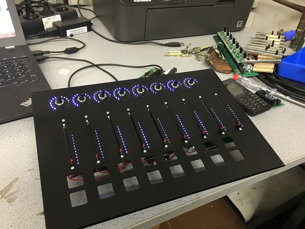
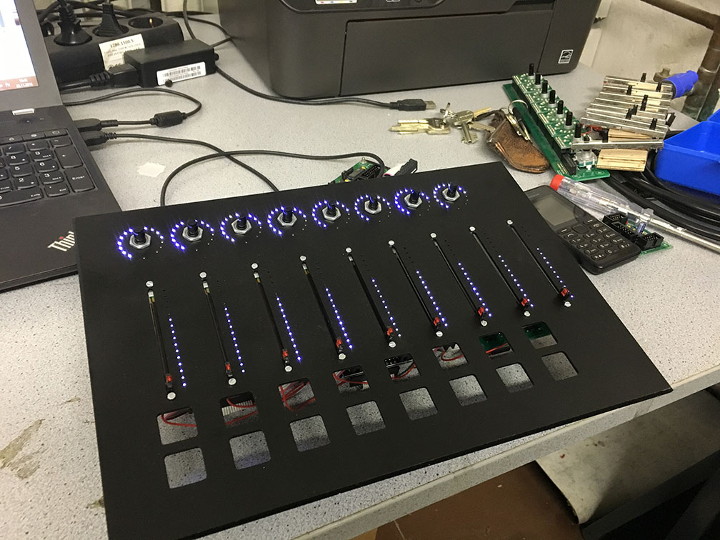
If you are able to do SMD soldering, you can simply use my designs. I need to update my wikipage... if you are interested in the designs. They are all working.... and they look like this: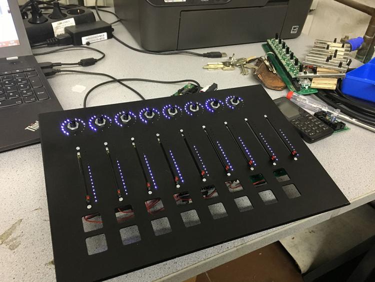
-
Hey people! The NG manual says that it's possible to dim LEDs which are in a matrix. I now have some LED-rings for encoders and I'd like to dim them to get a smooth transition between the LEDs. Is that possible? Here is what I've tried: RESET_HW DOUT_MATRIX n= 1 rows=8 inverted=1 sr_dout_sel1= 1 sr_dout_r1= 2 sr_dout_r2= 3 EVENT_ENC id= 6 hw_id = 6 bank=1 fwd_id=LED_MATRIX:6 fwd_to_lcd=1 type=CC chn= 1 cc= 21 range= 0:127 offset= 0 ports=1000100000001000 EVENT_LED_MATRIX id=6 type=cc cc=21 dimmed=1 colour=0 ports=1000100000001000 Any hints on this? Thanks! Chris
-
Hey, I used the newest version of NG. Any keyboard related changes I made in the NGC file do not influence the keyboard-signals. If I enter "kb 1" in the terminal, it also shows totally different values than I entered in the NGC. If I make the changes via the terminal (f.e. set kb 1 slowest_delay 1000) it works.... but I can not save this value via store or save. I tested also with an old version (1.34b). There it works perfectly. Thanks, Chris
-
Hi TK, as stated in another thread, the STM32F4 used on the latest core seems to be an "end of life" product. Is there any replacement you plan? Thanks, Chris
-
As far as I know I have no 1pc-board. Only for 8pc. And I don't believe you will be under $6 p.pc. if you do the PCBs by yourself including the OLED and don't forget about the soldering...
-
You are totally right. But by using my breakout-PCB and the little display-adapters you will save a lot of soldering. Of course it doesn't make sense to use this kind of connection if you are just looking for one or two displays for your midibox. But if you need 8 or more, this will make things a lot easier. Anyway: My PCBs can be downloaded and manufactured by any PCB manufacture out there if someone is interested in using this. I uploaded the layouts a few posts above.
-
Hey, my design worked! I didn't have any problems with it. But: It's very hard to solder flex-cables by hand (as there are no sockets which have the same pin number than the displays). That's why I decided to spend a few bucks more and use displays with pinheader and created a breakout solution.
-
... this was too easy... didn't see it :-) I'll try it! Thanks!
-
Awesome!!!
-
No, I read somewhere in the forum that the host-mode will be supported by every application. My core is running NG. I assume that I'd need to configure the midibox before connecting a usb device to it? Because I (of course) can not access the midibox via the MIOS Studio anymore when using the usb host mode.