

jaytee
-
Posts
352 -
Joined
-
Last visited
-
Days Won
15
Content Type
Profiles
Forums
Blogs
Gallery
Everything posted by jaytee
-
I made a small batch of custom MB-6582 panels a couple years back. They’re black with white print, have a little “MB•6582” logo on them, and have a trippy graphic behind the mod matrix. I sent out four sets of panels to forum members for their own builds. Just curious if anyone ever got theirs put together. I want to see my babies out in the wild ;)
-
Also: Pictures are working now, looks good! Those filter caps are a little hilariously big, lol. And I love the rainbow knobs on the other synth! Reminds me of the original C64 marketing logos. I wanted to do something similar, but it’s relegated to just the feedback knobs around back.
-
I had originally planned on a standard barrel jack for power. I ended up going with the 7-pin DIN for a few reasons. Probably the main reason is that the header pads for a panel-mounted power jack are close enough to the edge of the board that they kind of interfere with placing a panelmount jack at the same location. You might be able to get around this by placing the jack higher up on the rear panel or elsewhere on the panel altogether, by using angled headers instead of straight, or by simply wiring the jack directly to the board (though this list option will make servicing in the future more difficult). The above hurdle could have probably been surmounted, but lo and behold, a 7-pin DIN connector randomly fell into my lap. I had been asking around for a source on the OG power switch, and a kind forum member hacked off a piece of original C64 PCB for me that contained both the DIN jack and the switch. Obviously this won’t be the case for y’all, but having the part in hand made the decision a bit tougher. Other, minor reasons I went with the DIN jack: no need to redesign that part of the panel (I had custom panels made but I didn’t want to change any more than I had to), and no possibility of using the wrong voltage/polarity power adapter ever. Attaching the new jack to a power adapter was really easy; don’t let that be the only reason you shy away from the DIN connector. That all said, if the part hadn’t magically appeared for me like that, I’d have probably figured out how to use a barrel jack. I’m afraid I can’t advise on how to adapt the DIN sized hole to a barrel jack though, that’s a tough one. I had planned on custom panels from the beginning.
-
Pictures not working for me
-
https://www.taydaelectronics.com/connectors-sockets/midi-connectors/5-pin-midi-connector-female-right-angle.html 32¢ apiece. Tayda also has 15-16% off coupon codes on their Facebook, which brings the price down to ~28¢ apiece. No MOQ, though they require a minimum total order of at least $5. Still better than buying 500 at a time.
-
Ask all the questions you like! Not like this forum is super busy anyway. I’m away from my synths at the moment, but I have a Mix Out jack wired up. IIRC, I used 10k resistors (pretty standard for passive mixing), but I’d have to double check that. I use the mix jack almost exclusively and I haven’t noticed any issues with output level.
-
Short answer: trust the MIDIbox build docs. It’s supposed to be a 22nF cap. Long answer: it’s fine to experiment with different values and types of caps. You should be socketing this cap anyway so that you can easily install 6581 chips at some point in the future, but that also makes it easy to experiment with different caps and see what sounds best to your ears. There are also a couple values in the MB SID firmware that let you calibrate the filter response. IIRC, you can adjust the response range as well as choosing either linear or log response (the latter depends more on which SID chip you have, but go ahead and try both to get an idea of the difference). Back to short answer: just stick with the recommended 22nF caps. The SID filter is never gonna be stunning or full of character, and the 22nF caps are known to work well.
-
Time to revive the old 2044 MIDIbox project: http://www.midibox.org/dokuwiki/doku.php?id=ssm2044_pcb
-
Grab an old CD case, score the front with a razor until you can make a clean break, epoxy it to the inside of your panel.
-
For cheaper parts with cheap shipping to US, I like Tayda (very cheap, regularly has 15% sales announced on Facebook, easy to order common parts like resistors and caps, but sometimes low quality, no-name parts), and I’ve been digging Arrow lately too (free shipping, often has lower prices on same parts as Mouser, only downside is hilariously wasteful packaging).
-
25V should be fine for averything. If you’ve got a power supply that puts out more than 12V, you may want to go a bit higher just for the power caps.
-
I would offer, but I’m in the US. I’m sure you can find a builder more local to you, but if all else fails shoot me a message.
-
https://www.sparkfun.com/products/11448 Something like these should work. Again, I’m not sure about current draw compared with “normal” LEDs. Might require some trial and error with the resistors in the LED matrix.
-
If I still had a spare set of the panels I made with the trippy graphic behind the mod matrix, I would send you one for free if you promised to install rainbow blinky lights in it. ;) On a more serious note, what Hawkeye said is right on the money. If you’re talking about the kind of LED that has just two leads and color-changes automatically, it can probably be done (no idea what kind of current those things draw though). It would be a masterpiece of rainbow barf and I heartily approve. If you want to actually control the color changing, or you want to use LEDs with more than two leads, you’re not going to be able to do it with the current MB-6582 PCBs. Would require a redesign of both the circuit board as well as a fair few code changes, I would expect. Way more work than I’d be willing to do, but again, I encourage any and all rainbow barf-themed projects, so I say go for it! ;)
-
Honestly that’s impressive that you got it off at all and only killed two pads in the process.
-
Just wanted to drop this link here: http://midibox.org/forums/topic/14564-building-the-mb-6582-control-surface-photo-tutorial/ It’s a bit hard to find over in the “Tips and Tricks” forum, but is an excellent resource on putting together the control surface part of the MB-6582. I followed this guide almost exactly.
-
Ah, you’re absolutely right, I missed that it was just a single core module and SID module. They mentioned multiple PSU options and my mind immediately went to the option a, option b, option c, etc from the Mb-6582 documentation. 7805 will work fine then, lol. The MB-6582 is a current hog but a single SID is pretty manageable. The switching regulator isn’t any more complex though—it’s a drop in replacement—but it’s *way* more expensive and not at all necessary for a small SID synth. Pay me no mind, I’ll back out ;)
-
I have noticed a few recent questions about how to power the MB-6582, so I figured I'd give this thread a little bump to make it easier to find. Additionally, I went ahead and added this tutorial to the wiki like I promised I would over a year ago. It's live now, and I went ahead and edited the main page to add "PSU Option E" to the list of power options. Hopefully this makes things easier on novice builders. Incidentally, I also cleaned the main MB-6582 wiki page up a little, removing some severely outdated links and adding links to the Modular Addict MIDIbox store. No more link to Wilba's 6582 megasale that hasn't been happening for over 10 years!
-
made a mistake
-
To clarify, your PIC *must* have the MIOS bootloader burned to it *before* you can upload over MIDI. If you ordered your chips from a vendor who pre-loads the PICs with this bootloader, you’re good. If you ordered blank chips, you need to use a special PIC programming tool to put the bootloader on first.
-
made a mistake
-
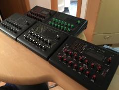
Just edited my post with a link to some pictures I took while I was trying to sell the excess. Ill snap a couple more right now though. Those pictures were taken to emphasize the flaws, as I was trying to be fully transparent about selling them, and don’t include any photos of the finished synth. IMHO, it came out looking pretty good. edit: forum software hates my pictures (too big?) but here’s a link to some quick photos of the finished synth: https://imgur.com/gallery/a7Zsgz2
-
Now that SmashTV has closed up shop, I’m not sure about this one. You might make a post in the classifieds forum here, or maybe someone will see your post here and offer you some. Can’t hurt either to email Modular Addict about whether they’d consider carrying them; they were extremely responsive when I suggested they carry the MB6582-specific knobs. My suggestion: don’t use a C64 power supply. The originals will flake out on you, the replacements are pricey, and overall, it’s completely unnecessary and impractical. I wrote a detailed guide on how to modify the MB-6582 to run on a single-supply, based on altitude’s original work on the subject. edit: Here is the relevant tutorial. Really can’t recommend this enough. http://midibox.org/forums/topic/20376-one-mb-6582-one-power-supply-a-tutorial/ The tutorial mentioned above on how to use a single-supply also explains your options for a mixed SID environment. It’s a pretty trivial change if I remember correctly. I think 6581s run a bit hotter than 8580/6582s, but not significantly so, and installing the power option without actually installing 6581s has no downside except for the added cost of another Vreg. That said, I agree with the poster above who suggested sticking with an 8580/6582-exclusive setup. I know some people are in love with the 6581 sound, but the 8580 is (IMHO) the superior choice for use in a dedicated musical instrument. Lower noise, better filter/resonance, full use of combined waveforms... As well, I gotta agree that it’s nice to have four full stereo voices that all sound alike. Anyway, that’s just my totally subjective opinion on the matter; no matter what you choose, it’s not hard to implement the power supply. As far as I know, yes. Their boards are identical in design to the most recent Mb-6582 boards from Smash. I don’t know much about swapping out the LCD, but I know folks have done it. Run a search of the forum and you’ll find threads about it. IMHO, not really worth it. My LCD was affordable and looks pretty great; there’s no practical reason to “upgrade” and there’s very little cosmetic reason even. I’ll find a link to the one I used. I really like it. It’s audible “in the room” so to speak, though quite quiet still, but more importantly, I cannot hear it in the MB-6582’s output. edit: the fan I used can be found here: https://www.amazon.com/dp/B00NEMGCIA/ref=cm_sw_r_cp_api_aTqOBbTFRP1N8 That said, it’s probably not necessary. Heat sinks...for the SID chips? I didn’t bother; I don’t think most folks bother. If you’re installing a fan, I definitely don’t think it’s necessary. If you’re using 8580s, probably not necessary. If you forgo the fan *and* install 6581s...I would still rank it as “probably not necessary though not a bad idea.” Sorry though, I’m not sure which heat sinks would work either. Yeah, the panels are definitely the single most expensive part. There are a few options though. The acrylic could work. Not sure how well JB-Weld adheres to it. Importantly, none of the controls are panel mounted, so the panel itself won’t be under much stress. I’ve seen some MB-6582s encased completely in acrylic; not sure if I’ve seen any using the PAC-Tec case with acrylic panels though. Julian, a fellow MIDIboxer, makes high-quality panels. That might be the £85 option you saw—thebeast.co.uk or something? Pricey, but by all accounts worth it. Front Panel Express is also pricey, but also high quality. Could be a good option if you want something very fancy and customized. What I found to be the most cost-effective option, and what I used on my own personal MB-6582, is having PCBs printed on aluminum, with the soldermask as the main panel color and the silkscreen for my labels (you can even go crazy and use a copper layer for additional decoration). AllPCB in particular can print PCBs on aluminum, though even the normal PCB material makes a decent panel. The initial order is about as expensive as going with Julian or FPE, but the minim order is 5 panels, so if you don’t mind waiting, you can make most of your money back by selling the extra panels here on the forums. This option is nice because you can fully customize your panel at almost no extra cost. One caveat: these are still PCBs, from a PCB maker, so they are manufactured and shipped as if they would never be seen by an end user. Expect blemishes, scuffs, and small imperfections. I am 100% happy with how my panels turned out, and I can’t see the imperfections unless I get up close and inspect, but if you’re the type who demands total perfection, maybe not the option for you. Hoo boy. Those fucking power switches... I went through hell to track one down. The switch—along with the 7-pin DIN power port that is no longer necessary if you’re not using a C64 PSU—make a strong argument for customizing your rear panel. What I ended up doing was salvaging a switch and DIN connector from a busted C64. I might not have gone this route, but a forum member offered them to me, and I figured “what the hell?” They fit the PCB foot prints (cuts down on wiring) and they fit the existing panel designs (though it’s not a big deal to alter those designs). So if you have a busted C64 handy and don’t mind butchering it, it *is* a pretty handy option. If you don’t have access to those original parts, I would go with panel-mounted parts instead. The switch does have a modern equivalent, but I had trouble actually tracking down someone who actually had them for sale. BE CAREFUL. There is an easy-to-find part that *looks* like an identical match, but actually is not; the pins have a slightly different spacing or oft height or something. Instead, just get a standard toggle switch and modify the rear panel design to accommodate it. Same goes for the power jack. I don’t think 7-pin DIN ports are impossible to find, but they aren’t exactly common, and if you’re using a single-supply PSU, all you need is a standard power jack. I used the 7-pin DIN because I had it handy, but it required me to buy a male DIN plug and modify my power cord. A standard panel-mounted barrel jack is probably the better option. If you do a PCB panel, modifying the panel designs before having them manufactured is not as scary as it might sound. I had zero experience with PCB design software or panel design before I started, and I just learned along the way. I didn’t end up modifying the power switch/jack parts of the panel, but I did alter a few other things about my panels and it went quite smoothly. I added some graphics, text and mounting screwholes to the front panel, and on the rear I added a 1/4” “Mix Out” jack with label, right above the power switch. edit: here is a thread with some information about the correct switches, as well as a few other notes on the BOM that might come in handy: http://midibox.org/forums/topic/20281-mb-6582-bom-questions/#comment-176598 edit: and here is the thread where I was selling my PCB panels. I’m all sold out now, but it has lots of pictures to give you an idea what these types of panels look like in the end. http://midibox.org/forums/topic/20402-fs-cheap-mb-6582-panels/#comment-177811 Congrats on the impending MB-6582!
-
Sorry if I missed this, but how much SMT soldering is there? I prefer thru-hole, not so much because of the soldering but because I can actually see the components... This looks amazing, but it’s definitely the “deluxe.” Not sure I need a sequencer with $120 worth of displays in it. ;)
-
 I always thought my sammichSID was my favorite synth, so I built an MB-6582 so I could have my "sammichSID" plus three backups...but now I'm realizing I need a backup MB6582 or several.... Although, I will say I really like the direction the FPGASID project is headed.

