

jaytee
-
Posts
352 -
Joined
-
Last visited
-
Days Won
15
Content Type
Profiles
Forums
Blogs
Gallery
Everything posted by jaytee
-

Possible new case option, without needing Heidenreich group buys
jaytee replied to julianf's topic in MIDIbox SEQ
Yeah the V4+ is leaving me in a quandary. On the one hand, it looks awesome and will probably represent the new "standard" SEQ build. On the other hand, if the Wilba CS PCBs every come back into stock, I'll be pretty hard-pressed to opt out of a build that is documented and ready-to-go, as opposed to the SEQv4+, which is still being planned and is not guaranteed to ever see the light of day (no offense to those working on it, I have faith in you! I've just also seen a fair number of ambitious MIDIbox projects proposed and get tons of attention before ultimately being dropped for being too ambitious). But don't recess the nuts! Go big or go home! -
Possible new case option, without needing Heidenreich group buys
jaytee replied to julianf's topic in MIDIbox SEQ
That looks fantastic. I am not usually a fan of exposed screws on wooden parts, but I actually really love those chunky end-nuts you put on there. Estimated price? -
If you wire things up exactly as shown here, C3 is only connected to the output of the 5V regulator, so a 16V rating is fine. It does occur to me that C1 (listed as 16V or 25V in the official BOM) should definitely be rated for 25V minimum (maybe even higher), especially if you're running mixed SIDs and therefore need a 15VDC wall wart. I'm pretty sure the one I have installed is still just a 16V, d'oh!
-
It seems to me that at the very least, this setup poses no greater risk than the original power setup, and in many ways reduces the risk. In the old design, the 5V line came directly from your PSU, so if it went haywire, it exposed the MB-6582 internals directly to whatever it was outputting. In this setup, everything past the power section is behind regulators at least. Wrong polarity will probably blow something in the power section, though I think the regulators protect everything else in that situation. If you wire up your own 7-pin DIN wall-wart like is shown earlier in the thread, it'll be pretty impossible to plug in something of the wrong polarity unless it's a mistake in your wiring; I say just be extra careful. Overvoltage is tolerated up to a point; check your regulator data sheets to see what kind of voltage input they can tolerate. If input voltage goes beyond that, they'll either shut down or break. I'm not sure what the failure mode of these regulators is (i.e., if they leave an open circuit, short to ground or short to input voltage), but in any case, they'll do the same thing in the old design too. The only protective measure that this setup removes is the bridge rectifier, which would technically protect against polarity reversal, but is really meant to rectify the 9VAC from the C64 PSU. The original design has no polarity protection for the 5VDC line, for instance, aside from the keyed power connector. If it really worries you, you could probably leave it in—sammichSID has a bridge rectifier alongside a single DC supply, for instance, but that's because it uses a standard barrel connector and could therefore be connected to any number of power supplies. The DIN connector on the MB-6582 prevents that. IMHO, it's safe enough. Maybe someone else can chime in with additional protective measures you could take.
-
I don't think there's any significant advantage to powering your MB6582 with a commodore64 PSU or especially a clone of one. As I understand it, it was built to run from the C64 PSU mainly because people building SID synths were expected to already have at least one lying around from a murdered C64, and because alternative methods for getting a regulated 5V supply at the time of design were either bulky, noisy, or hot. Nowadays, I don't see much reason for not going with a single voltage power supply and an internal 5V sVreg. It will certainly be cheaper than this solution, and I don't see any reason the C64 clone PSU would be superior. It makes sense for powering a C64, though! Check out this thread: and see what you think.
-
"oscillators are not completely silent once a note has been played"
jaytee replied to fallenturtle's topic in MIDIbox SID
There may be software tricks to get around it; I think it's somewhat related to the ADSR bug, so maybe the same workarounds apply? -
Just curious, what other parts (if any) did you order from Tayda? 99.9% of the time, Tayda parts are OK, but every once in awhile they'll send out bad batches of parts, and sometimes those parts are not truly broken but just way out of spec. Just a random thought, maybe you get lucky.
-
Rats, it would have been handy if C4 were the issue. Definitely still try a different outlet and adapter. And it seems unlikely, but maybe try replacing C1, or perhaps even upping the value slightly (3300uF)? TBH, we are rapidly approaching the limits of my knowledge here. If none of the above solve it, it may be best to start a new thread, since it would seem that your power section isn't the issue. Hopefully that will attract the attention of any folks who know PICs and/or Core8 modules better than I do.
-
Also, this probably isn't the issue, but looking at your solder side photo, there seems to be a few stray flux and solder blobs on the board. None that look like they're your issue, but it can't hurt to clean things up and go over it with a magnifying glass on the off-chance you have a tiny short somewhere.
-
Also, unrelated to your current issue, but possibly going to save you trouble in the future... As currently wired, you will not have a working 12V rail. I noticed in your earlier picture that all your jumpers were set for 9V operation, so maybe you're already aware, but right now, your 12V regulator doesn't have anything going to its input, and even after jumpering the connection, a 12V wall-wart won't be able to drive the 7812 properly. If you're planning to use only 6582/8580 SIDs, no change is needed.
-
The only thing jumping out at me from the photos is that you've left C4 (100nF) unpopulated (looks like V1 covers up the pads). C4 is in the original Core schematic (designated there as C3, confusingly enough), it does connect to the possibly problematic 5V rail, and it's the only notable difference between our builds, so it's worth a shot. Maybe you need to surface solder it to the backside to avoid desoldering your sVreg? Off the top of my head, perhaps the switching Vreg introduces some high frequency noise that mucks with the PIC, and C4 filters that out. It's possible that the troubleshooting document you posted never anticipated the use of switching supplies or regulators, and was therefore focused on the low frequency ripple that the big cap would smooth out. Also, just to check, you are getting a good 5V supply, correct? If you haven't checked since you started having issues, check that now, just to be sure.
-
The K2000 really is a fantastic synth, but I just don't find myself using it much. Between that and a general desire to go all-DIY with my setup (and with that, - need to find my TTSH build), it's time to say goodbye. Ive been trying to sell it for a month or two now, but my motivation level has only just risen above "barely attempting" so I'd like to give it a little more time to sell as a whole unit. If I don't get any nibbles soon, though, the sampling section is yours. Feel free to give me a nudge if you still see this up in a few weeks and haven't heard from me.
-
Even the 1.5A sVreg might choke with an excess capacitance load (it does mention this in the datasheet IIRC). I can't say for sure as I never tested. Even the 1A version worked once I pulled C3 (though I never tested it with LEDs). Anyway, looking over the Core8 schematics, I'm reasonably sure that C3 is not your issue, as the MB6582 C3 is not equivalent to the Core8 C5 when wired up according to the instructions in this thread. The Core8 C5 (and the MB6582 C3 according to the original power setup) is on the input of the 5V regulator. If you've wired everything according to the instructions here, C1 on the MB6582 takes that role, while C3 is now on the output of your 5V regulator (taking over the role of C4 on the Core8 board). In other words, if there's a capacitor to blame (and your wiring job is correct), I would look to C1 first rather than C3. Is it in backwards? Soldered correctly? Missing any jumpers? Barring that, what kind of power adapter are you using? How's the wiring where you live? It seems to me that if a too-small decoupling cap on the power rail can disrupt MIOS, then an abnormally noisy or otherwise poor-quality power source could cause the same symptoms (just a guess). If you can post some close-up, in-focus shots of your board's power section (top and bottom), there might be something there one of us could spot. I would also try a different adapter and a different outlet (in a different building if possible). Let's knock out some of the easy troubleshooting steps before we start mucking with component values (especially since my board and others work fine with these component choices).
-
If you want to try putting the 2200uf cap in while you get MIOS loaded, it should work ok. (Edit: Looking back over the schematics, I dont believe this will solve your issue.) Or at least, it worked fine for me until I installed more than six SID chips; only then did the switching regulator start to choke. OTOH, I haven't had trouble uploading MIOS since changing C3 to the smaller value, so I can't really say what the issue is.
-
"oscillators are not completely silent once a note has been played"
jaytee replied to fallenturtle's topic in MIDIbox SID
I use a software gate but yes, they're all basically equal for this purpose. The downside is some loss of dynamic control. In a mix you won't likely notice anything, but solo, you might hear the signal getting turned on and off by the gate. It's a trade off between that and the VCA leakage. -
SOLDSelling my beloved sammichSID. No SIDs included (though I can share some tips on where to find them). I always swore I'd never sell this synth, and I wouldn't have, except that I just finished building my MB-6582. I pulled the SIDs from the sammichSID to fully stuff the MB-6582, and as much as I love this little guy, I just don't need another SID synth around. This was the first real big DIY project I ever did, so there may be a couple soldering joints that don't look pretty, but it powered on the very first time I tried it and it has never given me even a hiccup in the five years since. $400, which is what I paid for the kit. No trades, but I may be open for negotiation. Again, just to be absolutely, 100% clear, there are no SID chips included with this sammichSID; you will need to source them yourself if you want this synth to make any sounds (in the meantime, the synth still turns on and works, so you can always blindly design new SID patches ). Edit: also selling some non-midibox gear, happy to combine shipping/negotiate prices for package deals if anyone is interested: CZ-101 $150 Kurzweil K2000RS with a couple minor issues $250 Beat707 x0x-style MIDI drum sequencer $150 Edit: added some photos


-
For the last four or five years, all of my MBSIDing was confined to a sammichSID. Since there's only one core in a sammichSID, I never used or tried to learn ensembles much. All I really understood was that a few global settings are stored in the Ensemble section, and that if my patches were acting weird for some reason, it was probably because I had accidentally switched Ensembles. I've just built a fully-stuffed MB-6582, though, so it seems like it's time to figure out ensembles. I understand the basic premise, I think. An ensemble is a snapshot of what all four cores are doing, right? Just one patch for each core, plus the global settings? What I'm more curious about is how folks are using and storing ensembles. E001 seems kind of useless, since it's liable to be overwritten with the firmware. So I guess E002 should probably be my default. Set up global settings to work with my hardware setup and use E002 as a scratchpad; then copy to the next available location every time I come up with a setting I like? Do folks find that they set up ensembles very often, or do most folks tend to deal with patches on a core-by-core basis and only set up an ensemble as strictly necessary? This is really my only multi-output, multitimbral synth, so I'm not entirely used to this in my workflow is all, just looking for ideas as to how others use this feature. TBH, the primary drives behind wanting an MB-6582 were the control surface and the super-poly mode (plus, as long as the hardware supports it, I may as well build the most badass synth I can!). The ability to run four MB SID cores independently is just a really nice bonus that I'm not sure how I'll utilize.
-
@ChinMuzik, you may also want to check out this thread on the topic. @jjonas used some very tiny headers that seem to work well, although apparently the crimping tool for them is expensive. It also seems that the cheaper and more common DuPont-style will work (tightly) on the CS board, just not the base board. Personally, the more I thought about it (and the more I thought about how I use my other DIY instruments, especially my sammichSID), the more I realized that I wasn't likely to be opening and closing the case very often once it's all built. With that in mind, I just soldered a whole bunch of individual wires, cut and stripped to the same length (got the idea from Altitude) . It was time-consuming, but probably not worse than crimping 60 wires would be. This way, it's perhaps slightly more prone to failure than using connectors (which I think is well-mitigated if I rarely open the case again), but one wire failing is trivially easy to replace.
-
I'm sure it's possible to disable the sammichSID LEDs in the firmware, but I couldn't tell you where. You can use any MB SID firmware with any SID chip. The only difference as far as I'm aware is the default filter settings are calibrated for one chip and not the other, but this can easily be changed in the MB SID menus on a per-ensemble basis; no need to muck around in the code. Even if you don't change it, it will still work fine, you'll just find that the cutoff controls don't have a very useful range of values. Personally, I don't like the default 8580/6582 values anyway. You definitely want the exp conversion on, but I don't know why the cutoff defaults to such a small range for the 8580.
-
"oscillators are not completely silent once a note has been played"
jaytee replied to fallenturtle's topic in MIDIbox SID
Yes, this is a bug of the SID chip itself, they all do it. I usually run my MB SID through a noise gate. -
Looking over the documentation, I'm convinced that J73 is basically vestigial, left over from when the design of the MB-6582 was mostly hypothetical. Wilba seems to have really tried to make the power section as versatile as possible, to allow for a number of different power configurations, but in the decade since the design was released, most folks seem to have opted almost exclusively for one of about three common options. The only scenario in which you don't need J73 is one where you're using a PSU that supplies separate voltage rails right out of the box, *and* you're not using the on-board switch. In this scenario, you'd just connect all respective supplies to J4, which is a direct connection to the different rails and bypasses the entire power circuit and switch. Even in this scenario, bridging J73 is unlikely to make any difference, as it will only connect a couple smoothing caps to the 5V line (if they're even stuffed). Those extra caps may be beneficial (smoothing out the 5V rail somewhat) or they may cause problems (if your 5V supply comes from a switcher that doesn't like excess capacitance), but no matter what, it's quick and easy to get working. Basically, unless you're doing something funky in your power section, just put J73 in.
-
Check out the gallery images that @urtzurd posted (on main page of forum). You can see that the female connectors are pretty short, especially compared with the more common DuPont-style. I said it in the gallery comments, but it bears repeating: these are some of the cleanest MB-6582 internals I've seen. Looks damn great.
-
All connectors with molex headers, nice but too tight
jaytee commented on urtzurd's gallery image in Finished MIDIboxes
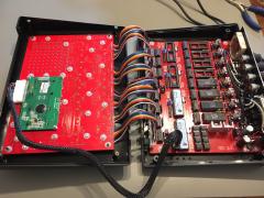 This is some of the cleanest looking MB-6582 guts I've ever seen. Bravo.
 -
This is a five year old thread. You'll have to wait for them to come back in stock at @smashtv's shop like the rest of us.
-
I think cracking the adapter open is probably a dangerous idea. Small chance you'll ever get it back together. I would either deal with the smaller gauge (after it's all built, how often are you going to be looking at the plug?) or install a panelmount 2.1mm barrel jack in the MB6582 so you can just use a stock adapter.
