

Phatline
-
Posts
1,285 -
Joined
-
Last visited
-
Days Won
72
Content Type
Profiles
Forums
Blogs
Gallery
Everything posted by Phatline
-
i can only speak for the JDM-Burner: when you upload MIOS8 you set the ID in the Uploader Program "ICProg"... i dont know how that work with this newer USB-"Burners"... look for ID value: its in HEX http://www.ucapps.de/mbhp_jdm_expired.html
-
https://vimeo.com/115565118 Freetekk vom Tekkstar...
-
its Done!!! and its a mod-ing dream... so its never done... the basic program is on it, now its time for more programming... bankstick, savings of routings, then routing banks for song-parts...roll routings, flame, tempo delay, mute... and at last a vca on the master...
-
From the album: TekkStar (Tama Techstar Midification)
connected to a korg Electribe Rythm MKII- which acts as Sequencer... -
From the album: TekkStar (Tama Techstar Midification)
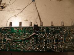
yes a fiew mods i want to make... but i need more pots and switches to do that... -
From the album: TekkStar (Tama Techstar Midification)
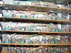
wires wires wires... i dont like that sandwitching... but it works... -
From the album: TekkStar (Tama Techstar Midification)
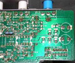
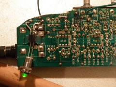
Very long Reverb time... Replace R306 with an 1MOhm Linear Pot then replace the useless "Reverb-time"Pot "VR32" with fixed 2x 47K Resistors (the pot is 100K and u can use it for other mods!!!) -
From the album: TekkStar (Tama Techstar Midification)
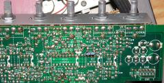
well have mode alot... not all what i want (lack of Switches and Pots...i have to order...) -
From the album: TekkStar (Tama Techstar Midification)
100K Resistor paralell to D5, switchable... causes a extrem long vca opening... -
jo stimmt hab fehl interpretiert ja so Oktaven shift taster, dast halt ohne menu usw direkt die oktaven hoch und runter schalten kannst und das pro SID-Chip... aber das ist nicht standart und müsst programmiert werden... ich bring halt einfach ein was ich brauchen würde... oh ja, da wüsste ich auch eine menge Parameter... mein sid cs muss noch warten bis ich A.assembler kann, oder B. sid in C kommt... seis wies sei stirbt kuh bleibts hei!
-
schau das sehr effizente LEDs in der Matrix verwendest...durch das ein und ausschalten in millisekunden bereich werden die selbst mit niedrigen Widerstand (bei mir 100Ohm) sehr dunkel... Taster immer vor Encoder setzten, oder zumindest mit größeren Abstand hinter den Encoder (Bedienbarkeit) Encoder unter das LCD setzten, um die Werte im Display leichter den Reglern zuweisen (kognitiv) zu können könnt ich assambler würde ich LEDRinge verwenden (siehe Nordrack III von Clavia) für die Keyboard Section würd ich 2 Octave-Shift +- Tasten und 4-5LEDs vorsehen. könnt ich Assambler würde ich für jeden SID 2 so Tasten und 5 so LEDs vorsehen--- das ist ein gutes kompositorisches Element wenns ums live spielen geht... Deto CUT-OFF und Amp-Decay regler... du hast ja platz in der kiste... nur programmieren musst es halt selber :shifty:
-

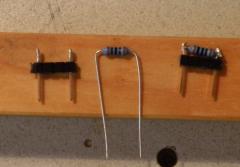
TekkStar_Mod_002_R56-Paralel-4K7-IC7-Overdrive.jpg
Phatline commented on Phatline's gallery image in Members Gallery
 finally i use 6K8 Resistors... all the other mods had made the voice loud!
 -
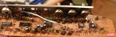
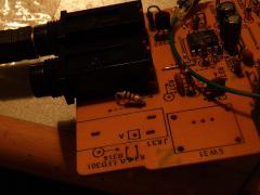
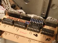
MODs off the Analog Part Mono-Mode (All Modules): if you just need 1 channel, it is a good idea, to remove follwing resistors to reduce Humming(alot): TomModule: Rm ClapModule: R360 SynthModule: R266 Why mono? Maybe you send the main to a mono vcf and vca? thats what i do...and this mode reduce the humming by my machine about half. SYNTH-MODULE: OverTone 1: solder a 470K Resistor paralell to R258(which isorginally also 470K) that overdrives the input of IC209 Overtone/Drive 2: R210 (200K) solder 100K parallel to > doubles the loudness and gives some overtones. You may try a pot... but dont forget to solder a savety-Reistor (dont know 1K) in series... to avoid to much current on the ics and Resistor (but i have noticed the board is very moding save...) Deeper Tune: turn the R223 1K Trimpot to most left... The Big BOOOOM: solder a 470K Resistor in series with a switch parallel to D203 CLAP-Module: Very long Reverb time: Replace R306 with an 1MOhm Linear Pot then replace the useless "Reverb-time"Pot "VR32" with fixed 2x 47K Resistors (the pot is 100K and u can use it for other mods!!!) HiPassFilter: Replace R342 with a 1K5 Resistor in Series with a 100K Potentiometer---- take that one that you have left from the "Very long Reverb time"-Mod! Make Place: Remove Plugs for Trigger, Pad, Each-out, and cut away the PCB, like in the picture, then: solder that little bridge over that Capacitor- that you see on the picture BASIC-Module (TOM): Distortion: R52 (470K)---replace it with an 470K Linear Pot.(Kick:808>909>Square) or replace it with an 220K Linear Pot. so it overdrives all the time a bit (Kick: 909>Square) >If you do this mod, dont change R56(10K) elswhere you will gett crackling< A bit Louder: R56(10K) parallel soldering a 6K8>8K thatdoubles the Volume, which you need if you dont have the Mixing board, that may blow up the Volume @main.... but that mode may crackle if you have made the Distortion mod... so let it be... The Big Booooooooom: Decay long to EVER-OPEN: by parallel soldering a 100K to D5 - it is a good idea to make switch for that (so long that it humms) Deeper Tune: Bridge R6! Emphasis Filter Frequency: (or is this Resonance?) Replace Rh by an 100K log pot in series with an 100K resistor, with 47K you get in self resonance...also 56K is in this shitty sound... better take a 100K TrimPot! Pinout of the Pot: when you look from the top of the 100K pot (where you turn) then take first 2 Pins (negativ log) let the 3rd Leg open If you dontneed the Attack-Pot (what is the trigger signal, in the signal path)then take that, by isolating the pins from the pcb, and do like above... ---I noticed that the lower frequencys are cut off a bit...better take a greater Resistance 470K or 1M! Changing the cap "CFm": let em out, give some really extrem high eardammage frequencys! holy for Highats! --let them out and solderm the 2 open leads to 2 contantacts at the frontpanel--- with your finger you can do some lopassfiltering ;))) 480p Stryflex Foil Capacitor - mid noise telephone speaker 18nf Foil-Capacitor for mid hi kick (magengrube) 10uF 36V Bipolar Elko for mid-low-kicks 100uf 35FV Bipolar Elko for sub kicks and bass BZX85C Diode --- sweeping 303 like sawtooth screaming LT132SBL3040- connect the 2 outerpins to get some "knackness" or any other Chip silizium germanium or whatever i decidet for one Switch Position- to install a socket on the frontpanel to plug in diodes or transistors directly.... holy that make fun...
-
From the album: TekkStar (Tama Techstar Midification)
Mono-Mode: if you just need 1 channel, it is a good idea, to remove follwing resistors to reduce Humming(alot): TomModule: Rm ClapModule: R360 Why mono? Maybe you send the main to a mono vcf and vca? thats what i do...and this mode reduce the humming by my machine about half. -
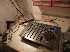
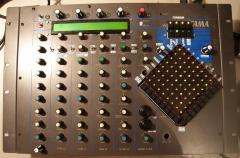
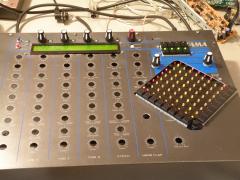
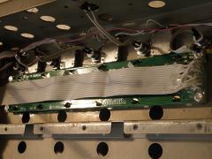
need place for the midibox stuff plug and play resistor socket for Matrix leds (150Ohm is to dark) make a resistor plug plugged in --- here 100Ohm and still to dark LED hole for Trigger Matrix --- dremel died lcd hole... made by hand (dremel is dead) lcd, menu encoder and analog trigger led the digitall inner Fully digitally stuffed
-
From the album: TekkStar (Tama Techstar Midification)
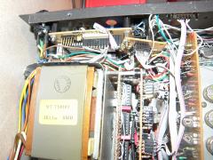
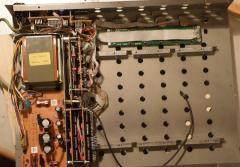
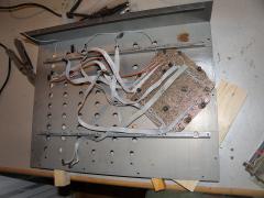
make place for midibox stuff.... -
From the album: TekkStar (Tama Techstar Midification)
make place on the analog part (place for encoder and display) -
From the album: TekkStar (Tama Techstar Midification)
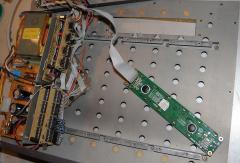
midibox stuff only -
From the album: TekkStar (Tama Techstar Midification)
all digitally in - all analog out -
From the album: TekkStar (Tama Techstar Midification)
trigger matrix ui-menue and so on -
From the album: TekkStar (Tama Techstar Midification)
a hole for the lcd -
From the album: TekkStar (Tama Techstar Midification)
time to flex the ui... -
From the album: TekkStar (Tama Techstar Midification)
with 100Ohm it still not bright enough... -
From the album: TekkStar (Tama Techstar Midification)
100Ohm Resistors for the Matrix
